Proton exchange membrane fuel cells are devices that directly convert chemical energy to electricity. A hydrogen oxidation reaction takes place on the anode side, generating protons and electrons. In the cathode, oxygen reduction reaction involving oxygen, proton and electron occurs, producing water and heat. The water content in PEMFCs should be maintained at a reasonable amount to avoid water flooding or membrane dehydration. The thermal management and water management of PEMFCs are important for an efficient and stable operation of PEMFCs. Inside the multiscale spaces of PEMFCs, multiphase flow with a phase change, heat and mass transfer, proton and electron conduction, and electrochemical reaction simultaneously take place, which play important roles in the performance, lifetime and cost of PEMFCs. These processes should be well understood for better designing PEMFCs and improving the thermal management and water management.
Proton exchange membrane fuel cells (PEMFCs) are devices that directly convert chemical energy to electricity. As promising next-generation power devices, PEMFCs have drawn great attention and have been extensively studied due to their many distinct advantages, such as high-power density, high efficiency, low-temperature operating and no-pollution. There are generally seven key components in a PEMFC, including catalyst layers, gas diffusion layers and gas channels on both the anode and cathode sides, as well as the proton exchange membrane sandwiched between them. In the anode catalyst layer, the following hydrogen oxidation reaction (HOR) takes place:
while in the cathode catalyst layer, the following oxygen reduction reaction (ORR) occurs:
Complicated reactive transport processes simultaneously take place inside the multiscale structures of PEMFCs. In the anode, hydrogen flows into the gas channel, diffuses inside the gas diffusion layer, and finally arrives at the catalyst layer for the HOR in Equation (1), which generates electrons and protons. The protons generated can conduct through the PEM to the cathode side, while the transport of the electrons in the PEM is not allowed and the electrons are transported through an external circuit to the cathode side. On the cathode side, the oxygen is fed into the gas channel, which then diffuses into the gas diffusion layer and further into the catalyst layer for the ORR described in Equation (2), leading to the generation of water.
The effects of water on cell performance are complicated. On the one hand, water has to be removed from PEMFCs, because too much liquid water will block the pores in PEMFCs and cover the reactive sides, which then hinders the transport of reactants and decreases the electrical reaction surface area. Such a phenomenon is called water flooding. On the other hand, however, the PEM needs to be well hydrated to guarantee good conductivity of protons, as a PEM with a low water content leads to high proton transport resistance. Therefore, water content inside PEMFCs should be delicately managed.
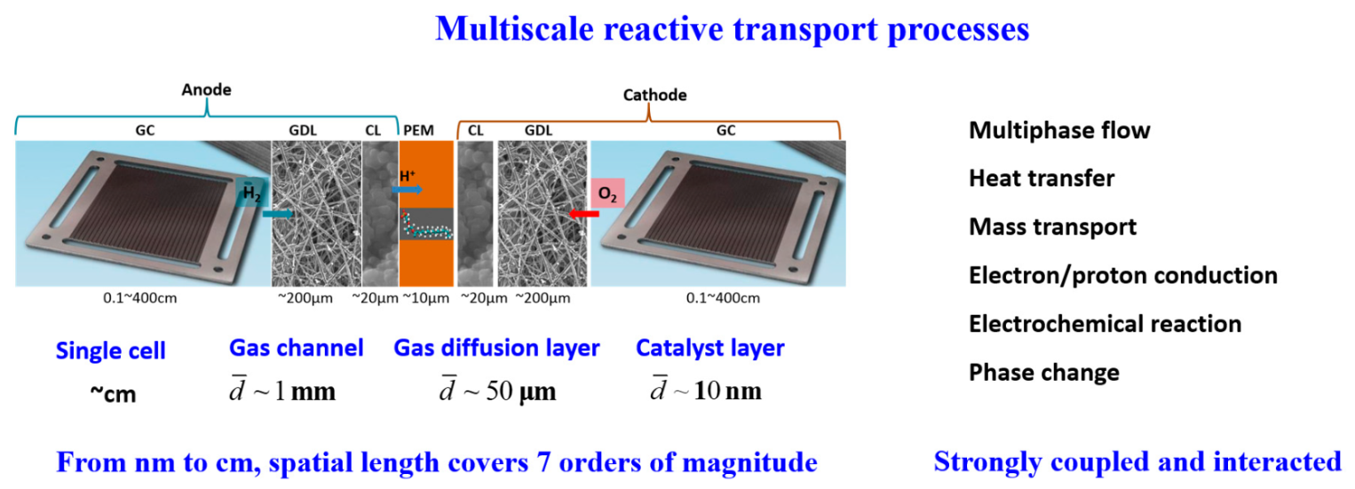
During the operation of PEMFCs, usually about 50% of the chemical energy is converted to electricity, while the other 50% is turned to heat. In other words, for a 1 kW PEMFC with 50% efficiency, 1 kW of heat is generated. Heat generated in PEMFCs includes the irreversibility of electrochemical reactions and ohmic resistance, as well as water vapor condensation. As mentioned before, in PEMFCs, the membrane should be well hydrated for preventing high ohmic loss and there should not be too much liquid water to avoid water flooding, thus PEMFCs are correspondingly operated at a temperature range of 60–80 °C. Therefore, the heat generated should be efficiently dissipated out of the PEMFC, and the balance of heat generation and heat removal maintains the desirable temperature-operating range of PEMFCs. In fact, the thermal management and water management of PEMFCs are coupled with each other, and together they determine the stable and efficient operation of PEMFCs. The thermal management and water management are very complicated due to the complex multiscale structures, the variation in surface properties of different components, as well as the temperature gradient inside PEMFCs. It should be noted that while the focus of the present encyclopedia is about low-temperature PEMFCs, high-temperature PEMFCs using PBI-based membranes and operating at much higher temperatures, where many of the transport processes related to liquid water, are no longer relevant. The structures of PEMFCs are in fact multiscale. The typical pore size in the catalyst layer is on a nanometer scale, while that in the gas diffusion layer is ~10 μm. The hydraulic diameter of the gas channels is about 1 mm, while the length of the gas channel or the size of a single PEMFC in the in-plane direction is at the magnitude of centimeters. It can be concluded that the reactive transport space inside PEMFCs covers about seven orders of magnitude, presenting typical multiscale characteristics.
From the above description, it can be found that complex reactive transport processes take place inside the multiscale structures of PEMFCs, including air–water two-phase flow with a phase change, heat transfer, mass transport, proton and electron conduction, and electrochemical reaction, as shown in
Figure 1. These multiphase reactive transport processes are inherently coupled and strongly interact with each other, and together, they determine the overall cell performance. In fact, the performance of PEMFCs is limited by three major losses, namely the activation loss due to the sluggish reaction kinetics of the ORR, ohmic loss due to the transport resistance of protons and electrons, and mass transport loss due to the transport resistance of the reactants (hydrogen and oxygen). Understanding the reactive transport characteristics, as well as the coupling mechanisms of the above-mentioned reactive transport processes is crucial for improving the performance of PEMFCs through reduced losses and enhanced water management and thermal management. In
Section 2, different processes within different components of the PEMFC will be introduced, and the key mechanisms will be discussed.
Figure 1. Multiscale reactive transport processes in PEMFCs.
This entry is adapted from the peer-reviewed paper 10.3390/encyclopedia3020054

