Your browser does not fully support modern features. Please upgrade for a smoother experience.
Please note this is a comparison between Version 1 by M. Shahinuzzaman and Version 2 by Conner Chen.
Perovskite, an organic–inorganic hybrid material, tends to be a promising light-harvesting material. PSCs (organic-inorganic perovskite solar cells) are considered a significant breakthrough in photovoltaics and have received great attention. Due to the inherent advantage of perovskite thin films that can be fabricated using simple solution techniques at low temperatures, PSCs are regarded as one of the most important low-cost and mass-production prospects.
- perovskite solar cell
- stability
- efficiency
1. Introduction
Perovskite, an organic–inorganic hybrid material, tends to be a promising light-harvesting material. In 2009, the Miyasaka group [1] reported a perovskite solar cell (PSC) of 3.8% using a DSSC system configuration with liquid electrolyte based on MAPbI3 (MA = CH3NH3+). Park group [2] obtained a nearly doubled power conversion efficiency (PCE) of 6.5% in 2011 using a high concentration perovskite precursor solution. Since then, several efforts have been made to enhance PSC photovoltaic efficiency from various angles, including perovskite layer fabrication methods, interface engineering, cell architecture design, and development of the hole transporting materials (HTM), an electron transporting materials (ETM). A certified PCE of 22.7% has already been achieved via the above optimization [3]. Although the PCE currently available is appealing, the PSCs still have low stability (thermal, light, and moisture stability), which hinders their commercialization.
The discovery of high-efficiency and highly stable perovskite solar cells has sparked extensive research, which is still ongoing [4][5][4,5]. Particularly, organometallic semiconducting perovskite has a direct band gap with high absorption coefficients [6] that enables efficient light absorption in ultra-thin films. Furthermore, it has a long diffusion length [7][8][9][7,8,9], low exciton binding energy [10][11][10,11], high carrier mobility [12][13][12,13], and simple and easy preparation techniques [14] that help to get high efficiency and low-cost showing promising alternative to the conventional crystalline silicon-based solar cell. Moreover, perovskite materials can be implemented in two different cell structures, either as planer (n-i-p) or inverted (p-i-n) architecture. Moreover, both architectures could be (i) regular structures in which no mesoporous layer is employed, and (ii) mesoscopic structures where a mesoporous layer is needed. The significant improvement in efficiency already achieved in all kinds of architecture, and the stability of PSCs remain the key concerns for the researchers at present time. Many changes were made to the working electrode, the electron transport layer (ETL), and the hole transport layer (HTL) to improve their stability and charge transport properties. The hole transporting materials is a very much important factor in PSCs to achieve high efficiency and performance. It acts as the mediator to transfer positive charges (Holes) between the perovskite and counter electrode [15]. Particularly, highest efficiency (PSCs) are achieved with organic HTL such as 2,2,7,7-tetrakis-(N,N-di-pmethoxyphenylamine)-9,90-spiro-biuorene(spiro-MeOTAD) [16]. The other most commonly used organic HTMs are poly(3,4-ethylene dioxythiophene) (PEDOT) or poly(3,4-ethylene dioxythiophene):poly(styrene sulfonate) (PEDOT:PSS) [17], poly-[[9-(1-octylnonyl)-9H-carbazole-2,7-diyl]-2,5-thiophenediyl-2,1,3-benzothiadiazole-4,7-diyl-2,5 thiophenediyl] (PCDTBT) [18][19][18,19], poly-[3-hexylthiophene-2,5-diyl] (P3HT) [20][21][20,21], 4-(diethylamino)-benzaldehyde diphenylhydrazone (DEH) [22], poly-triarylamine (PTAA) [19][23][19,23], N,N-dialkyl perylene diimide (PDI) [24], polypyrrole (PPy), polyaniline (PANI) [25], etc. From a commercial standpoint, the production of solar cells utilizing an organic hole transport layer has encountered numerous challenges, the most significant of which are material cost and stability. Particularly, high purity spiro-OMeTAD is more costly than novel metals such as gold and platinum, which are commonly used as a counter electrodes. Commercially available spiro-OMeTAD is nearly ten times more expensive than platinum and gold. On the other hand, organic HTMs are typically hygroscopic in nature and that’s why it has an impact on the PSCs’ general stability.
In contrast, several low-cost inorganic HTLs were also proposed and implemented for enhancing the stability of PSCs, among them, some of the HTMs are CuSCN [26], NiOx [27], Cu2O or CuO [28], CuI [29], CuGaO3 [30] and CuAlO2 [31], MoOx [32], CuS [33], MoS2 [34], and polymer electrolyte [35]. The above-mentioned HTMs have shown potential as they offer suitable properties for application in PSCs including the suitable band-to-band alignment with the perovskite layer, low resistivity, and low-cost solution-process ability [2]. In the case of inorganic HTM, increased demand for inorganic HTM will certainly lower the cost of large-scale manufacturing, while organic HTM will likely stay expensive due to the preparation processes and materials with very high purity required for solar cell applications. These are the primary reason why researchers have concentrated their efforts on the development of an inorganic HTM. Consecutively, the quest for the perfect HTM is a great topic yet. There is a lot of literature on various HTMs, but only a few of them show promise in terms of improving the overall efficiency and stability of the PSCs. Several approaches have evolved to utilize inorganic p-type semiconductor materials, such as NiOx, CuOx, etc., focusing on developing non-hygroscopic and highly conductive HTMs [36]. Moreover, carbon-based materials, including graphene, activated carbon, carbon black, graphite powder, carbon nanotube (CNT), etc., have been employed in the case of HTM-free PSC structures [37][38][39][40][37,38,39,40]. In particular, current approaches to HTMs are low cost, high mobility, low absorption in the visible region, ease of synthesis, and good chemical stability that could ensure high efficiency and stable PSCs. In recent years, several review works have been published on inorganic metal oxide hole-transporting materials for perovskite solar cells in different formats and among them, some are focused on fabrication way, some are on efficiency and some are focused on stability. A list of some important review articles on inorganic metal oxide-based PSCs for the year 2015–2021 is shown in Table 1.
Table 1.
List of recently published review articles on inorganic HTMs for PSCs.
| No. | Title | Journal | Year | References |
|---|---|---|---|---|
| 01 | Recent progress of inorganic hole transport materials for efficient and stable perovskite solar cells | Nano Select | 2021 | [41] |
| 02 | A brief review of hole transporting materials commonly used in perovskite solar cells | Rare Metals | 2021 | [42] |
| 03 | Nickel Oxide for Perovskite Photovoltaic Cells | Advanced Photonics Research | 2021 | [43] |
| 04 | Toward efficient and stable operation of perovskite solar cells: Impact of sputtered metal oxide interlayers | Nano Select | 2021 | [44] |
| 05 | Inorganic hole transport layers in inverted perovskite solar cells: A review | Nano Select | 2021 | [45] |
| 06 | Progress, highlights, and perspectives on NiO in perovskite photovoltaics | Chemical Science | 2020 | [46] |
| 07 | A review on the classification of organic/inorganic/carbonaceous hole-transporting materials for perovskite solar cell application | Arabian Journal of Chemistry | 2020 | [47] |
| 08 | Review of current progress in inorganic hole-transport materials for perovskite solar cells | Applied Materials Today | 2019 | [48] |
| 09 | Recent progress of inorganic perovskite solar cells | Energy & Environmental Science | 2019 | [49] |
| 10 | Inorganic hole transporting materials for stable and high efficiency perovskite solar cells | The Journal of Physical Chemistry C | 2018 | [50] |
| 11 | Analysing the prospects of perovskite solar cells within the purview of recent scientific advancements | Crystals | 2018 | [51] |
| 12 | Recent progress in stability of perovskite solar cells | Journal of Semiconductors | 2017 | [52] |
| 13 | Emerging of inorganic hole transporting materials for perovskite solar cells | The Chemical Record | 2017 | [53] |
| 14 | Recent advances in the inverted planar structure of perovskite solar cells | Accounts of chemical research | 2016 | [54] |
| 15 | The progress of interface design in perovskite-based solar cells | Advanced Energy Materials | 2016 | [55] |
| 16 | Recent progress on hole-transporting materials for emerging organometal halide perovskite solar cells | Advanced Energy Materials | 2015 | [36] |
2. Perovskite Solar Cell
PSCs (organic-inorganic perovskite solar cells) are considered a significant recent breakthrough in photovoltaics and have recently received great attention [49]. The power conversion efficiency (PCE) of PSCs has already enhanced from 3.8 percent to 25.8 percent through the system engineering and materials design regarding the correct optoelectronic aspects in just 10 years [56]. Thus, PSCs are recognized as the best alternative approach for replacing the costly and market-dominant crystalline silicon solar cells [51][57][58][59][60][51,57,58,59,60]. Moreover, PSCs are more cost-effective than conventional inorganic semiconductor thin-film solar cells, such as CIGS and CdTe [52]. The real obstacle to commercialization, however, is maintaining long-term stability. PSCs are particularly susceptible to deterioration when exposed to moisture, oxygen, heat, and light, and they must address before they can use in practical applications. Perovskite is itself very reactive due to the presence of vacancies in its structure. This is the defect of perovskite and it can encourage ion migration through the perovskite layer. Furthermore, the organic cations which are used in PSCs are hygroscopic in nature. When the PSCs are contacted with moisture, the water molecule reacts with it and forms a weak hydrogen bond with the cation which results in the formation of a hydrated perovskite phase [52]. Oxygen, heat, and UV influence this chemical reaction and favor the instability of PSCs. For commercialization, PSCs must be able to operate without major degradation for almost 25 years in outdoor conditions [61]. PSCs have so far been claimed to have one-year stability, which is considerably less than the PV systems that are already on the market. Thus, it is evident that the stability and limited longevity of PSC PV are the main factors impeding its commercialization [62]. The basic building block of the perovskite structure, ABX3, is shown in Figure 1, where A and B are cations with different sizes (A being larger than B) and X is an anion [63]. Figure 1 represents the simplest structure made up of cubic symmetry of corner-sharing BX6 octahedra, where the B cations are in the middle of the octahedron and the X anions are at the corners [64][65][64,65]. In the gap of cuboctahedra, the A cations are located at interstices, surrounded by eight octahedral, and form a cubic Pm3m crystal structure [66]. In the case of frequently used perovskites in solar cells are organo-metal halide perovskite materials, where ‘A’ may be an organic or inorganic cation (i.e., MA+, FA+, Cs+, K+, and Rb+), while ‘B’ is a metal cation (i.e., Pb2+ or Sn2+), and ‘X’ is a halide anion (i.e., Cl, Br, I, etc.) [67][68][67,68].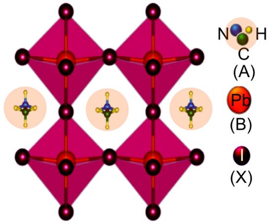
Figure 1. Crystal structure of perovskite with a general chemical formula of ABX3 (in the case of CH3NH3PbI3, A represents the CH3NH3, B represents the Pb, and X represents I).
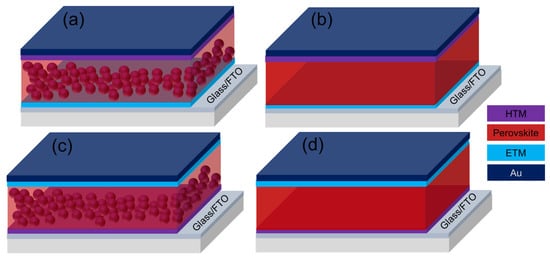
Figure 2. Device architectures of perovskite solar cells; (a) normal mesoscopic, (b) normal planar, (c) inverted mesoscopic, and (d) inverted planar structure.
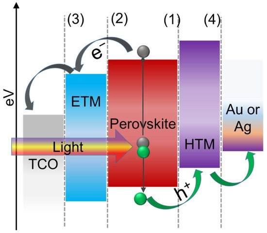
Figure 3. Energy level diagram and the carrier transport mechanism of perovskite solar cell in normal configuration (Interfaces in planar PSCs showing (1) HTL/perovskite interface, (2) perovskite/ETL interface, (3) ETL/cathode interface, and (4) HTL/anode interface).