Your browser does not fully support modern features. Please upgrade for a smoother experience.
Please note this is a comparison between Version 1 by Seyyed Masoud Kargar and Version 3 by Amina Yu.
Piezoelectric energy harvesters provide many different application scenarios by having flexibility in their structures, coupling modes, sizes and so on.
- piezoelectric
- energy harvesting
- ocean
- energy conversion
- atlas
1. Oceanic Piezoelectric Energy Harvesters
1.1. Piezoelectricity
In 1880, the term piezoelectricity was introduced by brothers Pierre and Jacques Curie [1][30], which has been intensively studied in recent years for different sensory and actuation applications in different fields. Later, in 1881, the brothers Curie validated their work on the inverse piezoelectric effect with experiments [2][3]. Stressing a piezoelectric material would result in a change in its atomic configuration, which forms dipole moments. This phenomenon is called the direct piezoelectric effect, in which the piezoelectric material generates electricity as a reaction to the applied force. Therefore, if a periodic force (tension or compression) is applied to the material, an alternative current (AC) voltage will be the output. On the other hand, if the piezoelectric material is electrically polarized, the converse piezoelectric effect appears in which the piezoelectric material extends/contracts as a result of the applied electrical voltage. It should be noted that in the inverse piezoelectric effect, lengthening or shortening of the piezoelectric material depends on the polarity and the applied poling voltage and can be reversed if the voltage direction is reversed [3][11]. Both the direct and converse effects of piezoelectricity are shown in Figure 1.
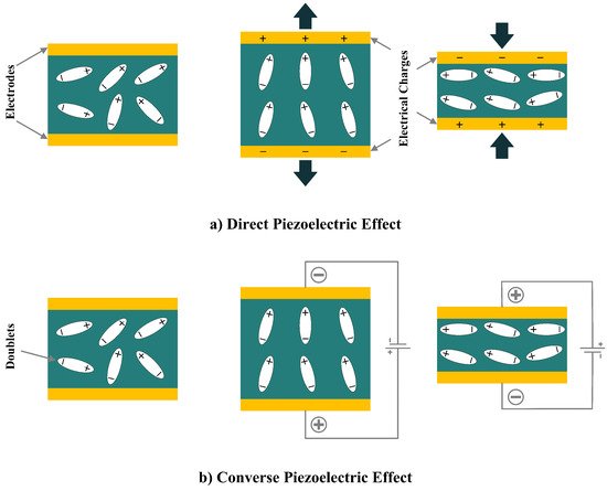
Figure 1.
Piezoelectric Effect; (
a
) Direct Piezoelectric Effect; (
b
) Converse Piezoelectric Effect.
There are many diverse applications for both direct and inverse piezoelectric effects, where the direct effect is utilized in the case of sensors and energy harvesters, and the inverse effect is used in actuators. These effects are governed by piezoelectric constitutive equations as [4][31]:


where D, d, T,
where D, d, T,
E
,
X
, and
s
, represent electrical displacement, piezoelectric coefficient, stress, the permittivity of the material, electric field, strain, and mechanical compliance, respectively.
1.2. Piezoelectric Materials
Active materials that can generate electricity as a reaction to small mechanical stress are called piezoelectric materials. The type of material for energy harvesting applications is of high importance to the performance and functionality of the harvester. Researchers have investigated numerous types of materials, such as organic, inorganic, composite, and bio-inspired materials, for piezoelectric energy harvesters [4][31]. Among them, PZT and PVDF are the most widely used materials for energy harvesting in oceanic applications. PZT, which is also known as Lead Zirconate Titanate, is a polled ferroelectric ceramic with the highest frequency of applications in piezoelectric energy harvesters. Even though the PZT is one of the major materials in energy harvesting, its drawbacks, such as its drastic brittle nature and fatigue growth possibility in high-frequency loadings, limited its widespread usage in energy harvesting. On the other hand, to overcome the demerits of PZT, PVDF, also known as polyvinylidene fluoride, is developed to improve the efficiency of piezoelectric energy harvesters [5][32]. Although PZT can produce more electricity when subjected to the same stress as PVDF, unlike PVDF, it cannot bear high stress. PVDF shows a higher tensile strength value, which is about 2.6 times higher than PZT’s strength value [3][11]. The low stiffness, large tensile strength, and high flexibility of PVDF make it a unique choice for many applications, specifically in ocean energy harvesters. Apart from PZT and PVDF, macro-fiber composites (MFC) are also used in some of the literature in ocean applications, which show great performance in energy harvesting from the ocean.
1.3. Coupling Modes
Piezoelectric materials present a kind of flexibility in their configurations, which makes them unique in energy harvesting applications. Based on the desired configuration in a particular application, piezoelectric materials’ configurations can be altered by changing their electrode pattern, poling direction, and strain direction. Moreover, to tune the resonant frequency between the material and the energy source, volume and layers can be changed, and a pre-load force can be added [6][27].
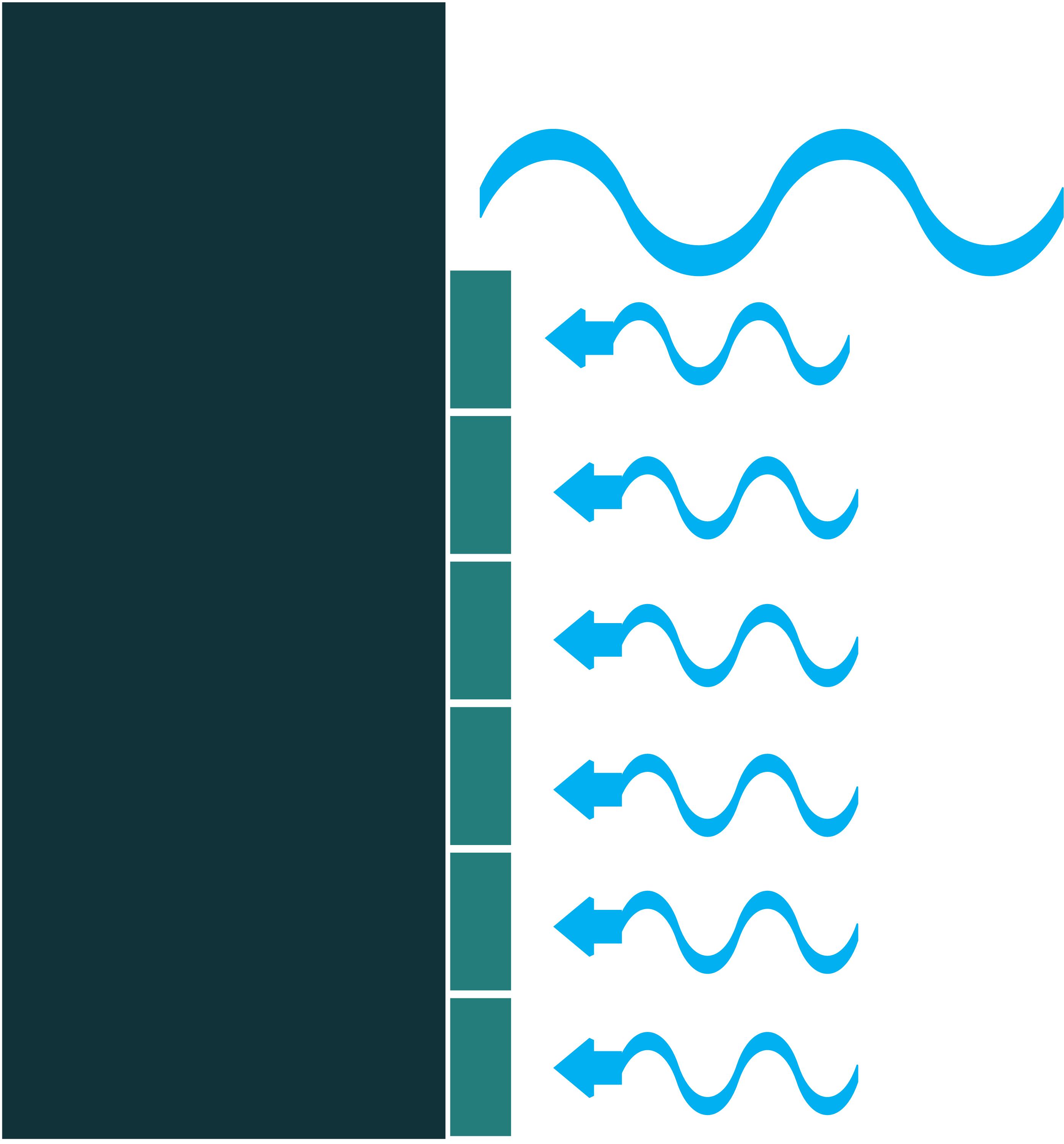
The piezoelectric coefficient (dij) is the ratio of the strain to the electric field, where i denotes the direction of the polarity and j represents the mechanical stress direction. Figure 2 shows piezoelectric material axes for polarization, as well as stress/strain. According to [7][28], d14, d15, d33, and d31, or simply 1-4, 1-5, 3-3, and 3-1, respectively, are the piezoelectric energy harvesters’ configurations in oceanic applications. However, due to the complex configurations of 1-4 and 1-5 modes, they are less used in oceanic applications compared to 3-3 and 3-1 modes. Figure 3 shows the most utilized configurations, 3-3 and 3-1, in ocean applications. In the 3-3 mode, both the polarity and the mechanical stress are in the same direction, parallel to each other. However, in the case of 3-1, the direction of the mechanical stress is perpendicular to that of polarity [8][33]. It should also be noted that choosing the right configuration for designing a high-performance piezoelectric energy harvester plays a crucial role and thus should be carefully considered based on the design requirements.
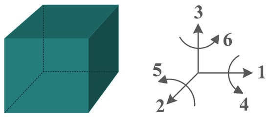
Figure 2.
Polarization axes of piezoelectric materials.
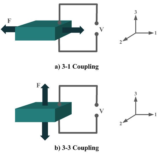
Figure 3.
Piezoelectric Coupling Modes; (
a
) 3-1 Coupling Mode; (
b
) 3-3 Coupling Mode.
1.4. Classification Based on Device Structure
The most common structure for a piezoelectric energy harvesting device is the cantilever beam configuration. This type of harvester employs one or two piezoelectric layers and is called unimorph and bimorph, respectively. Figure 4 shows cantilever beam structures with one and two layers of piezoelectric materials. As can be seen in Figure 4, piezoelectric layers are mostly bonded to a metallic non-piezoelectric material that is fixed at one end and acts as a flexural structure. As it is clear, taking advantage of two layers of piezoelectric materials, bimorph-type cantilever beams are capable of generating more output power compared to unimorph configurations. Therefore, bimorph configurations are of the high frequency of applications in piezoelectric energy harvesters [9][10][34,35].
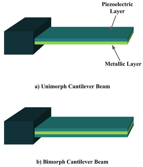
Figure 4.
Cantilever Beam Configuration; (
a
) Unimorph; (
b
) Bimorph.
Cantilever beam configuration utilizes the 3-1 coupling mode most often. However, there are designs in the literature that have used 3-3 coupling modes for cantilever structures, making use of interdigitated electrode designs. Moreover, it is usual to add a proof mass at the free end of the cantilever beam to tune the resonant frequency of the harvester with the environment [4][31].
The other configuration, which consists of a piezoelectric layer with a mostly disk shape, is the diaphragm structure. The piezoelectric layer is bonded to a metal shim. In some configurations, to improve functionality under low frequencies and to add a pre-loading unit to the energy harvester, a proof mass is attached to the diaphragm’s core (Figure 5) [11][36].

Figure 5.
Diaphragm Configuration.
Adding two metallic endcaps in the shape of a cymbal on both sides of a piezoelectric disk would result in a new configuration called the cymbal structure (Figure 6). This configuration is indeed used to improve piezoelectric endurance when it is subjected to higher loads and impact forces. Moreover, the cymbal shape of the endcaps acts as a mechanical amplification unit due to the presence of the cavity in the center [11][36].
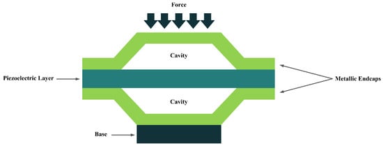
Figure 6.
Cymbal Configuration.
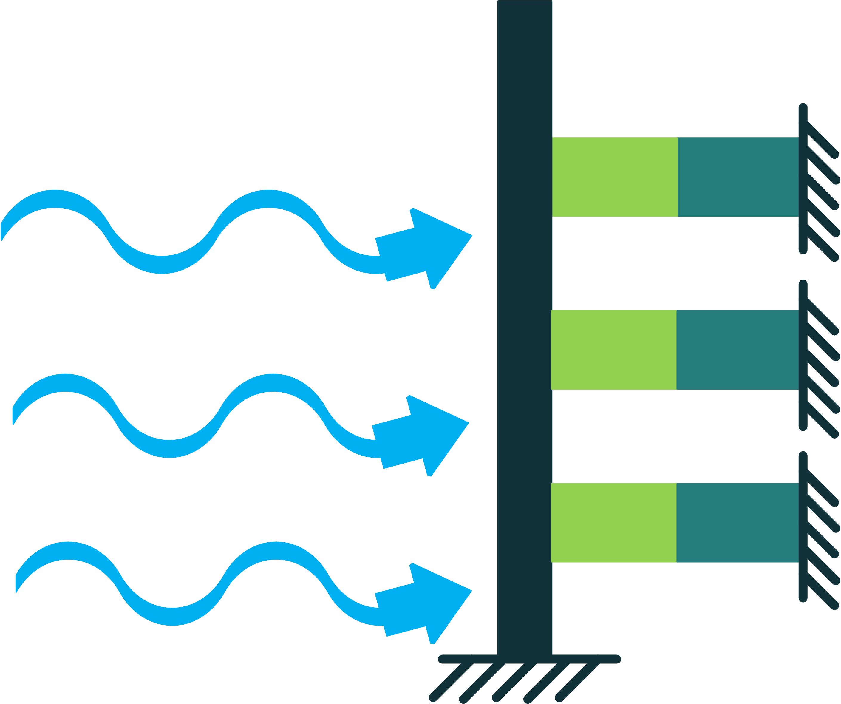
In addition to the other configurations, stacked piezoelectric structures can bear higher pressures. This configuration is made up of multiple layers of piezoelectric material stacked on top of each other. The poling direction of this type should be aligned with the applied force direction, as shown in Figure 7 [10][35].
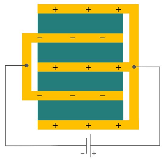
Figure 7.
Stacked Configuration.
All the aforementioned configurations have their own merits and drawbacks. Each of them may be suitable for numerous applications and unsuitable for many others. Therefore, before employing one of them in an application, their limitations should be carefully studied and considered. In addition to the cantilever beam configuration’s advantages, such as simple structure, low price, suitability for low-frequency applications, and higher mechanical quality factor, they are not able to withstand high impact forces. On the other hand, the cymbal configuration can bear impact forces and provide high energy output. However, the loss of mechanical input energy and being limited to applications requiring high vibration sources are its drawbacks. The circular diaphragm configuration is capable of working in pressure mode operations, but in a vibration mode application, it requires higher resonance frequencies. The stacked configuration is also suitable for working in pressure mode. It can also bear higher mechanical forces and provide higher outputs in the d33 coupling mode. Nevertheless, its high stiffness is among the challenges that should be addressed in the search for a proper application for it [11][36].
1.5. Power Harvesting System
The generated electricity by the piezoelectric energy harvesters needs to be further processed before any collection or storage in a power storage system. However, it should be taken into consideration that power storage systems, such as batteries, require direct current (DC) rather than alternative current (AC). If the piezoelectric harvester acts as a resonator, then the resultant voltage would be a sinusoidal signal, which should be rectified for any further applications. To carry out this operation, an intermediate step needs to be implemented to convert AC signals to DC. To do so, either the Standard Technique or the Synchronized Switch Harvesting on Inductor Technique can be employed [12][13][37,38]. By eliminating the ripple voltage, these techniques would smooth out the DC signal, and after regulation by the control system, the signal is ready to be stored in a power storage system. Figure 8 provides an illustration of the power harvesting operation by piezoelectric materials to further simplify the understanding of the process.
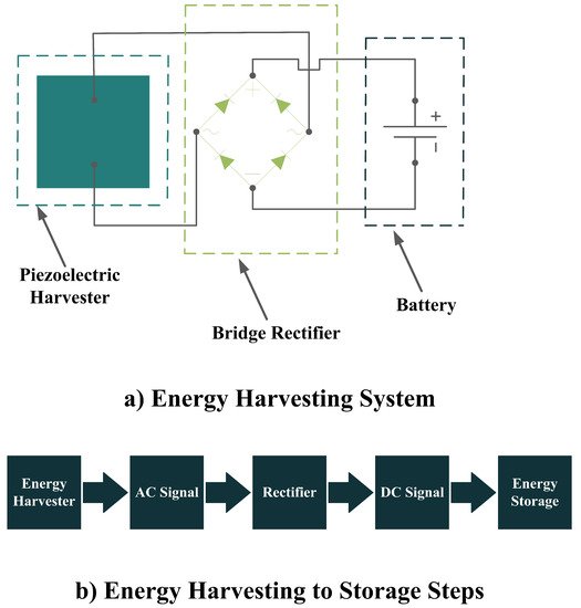
Figure 8.
Power Harvesting Operation; (
a
) Energy Harvesting System; (
b
) Energy Harvesting to Storage Steps.
In addition to the circuit shown in Figure 8, there should be an impedance-matching system in between to guarantee the high performance of the piezoelectric energy harvesters. Matching the electrical parameters with the source, cable, or receiver is of high importance for any electrical transmission line that is involved in the transfer of an electrical signal or power. Therefore, the impedance matching of the electrical parameters should be carefully considered in the design stage of the piezoelectric energy harvesters [14][39]. According to [14][39], matching of both acoustic and electrical components in a design should be considered for impedance matching. However, in the case of piezoelectric energy harvesters, the impedance matching of electrical components is more important. Piezoelectric energy harvesters are narrow-banded intrinsically, but a broadband operation is required for energy harvesting, in which acoustic impedance matching is employed to improve the narrow-band operation. However, it increases the electrical impedance and leads to an impedance mismatch between the harvester and the interface device. This mismatch diminishes the electric energy and requires an electrical impedance matching unit to be minimized. To do so, a shunt circuit [15][40], which is the simplest one for this purpose, can be employed to maximize the output electrical energy (Figure 9). One can refer to [14][15][16][17][39,40,41,42] for more information regarding the impedance matching of piezoelectric energy harvesters.
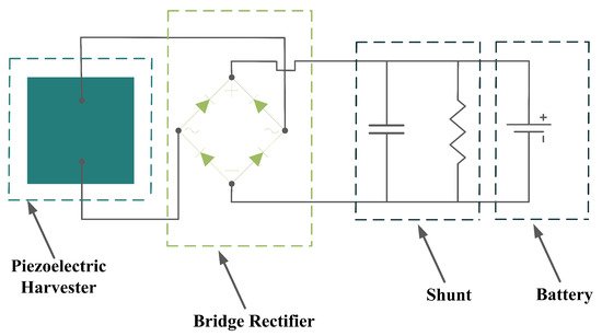
Figure 9.
Energy Harvesting System with an Impedance Matching Unit (Shunt).
1.6. Ocean Energy Sources for Piezoelectric Energy Harvesters
Marine renewable energies are the source of many different energy converters [18][19][5,43]. In the case of piezoelectric energy harvesters, water current, wave motion, and wave impact forces have been employed to extract energy from the ocean and convert it to usable electrical energy to power sensors and some other measurement devices [3][11]. These sources are very promising and available at all times during the day. Moreover, these energy sources in marine environments have a high density compared to the other sources of renewable energies, such as wind or solar energies [20][44]. In the following, a short introduction will be given to each of the marine energy sources that piezoelectric energy harvesters are designed for.
1.6.1. Water Currents
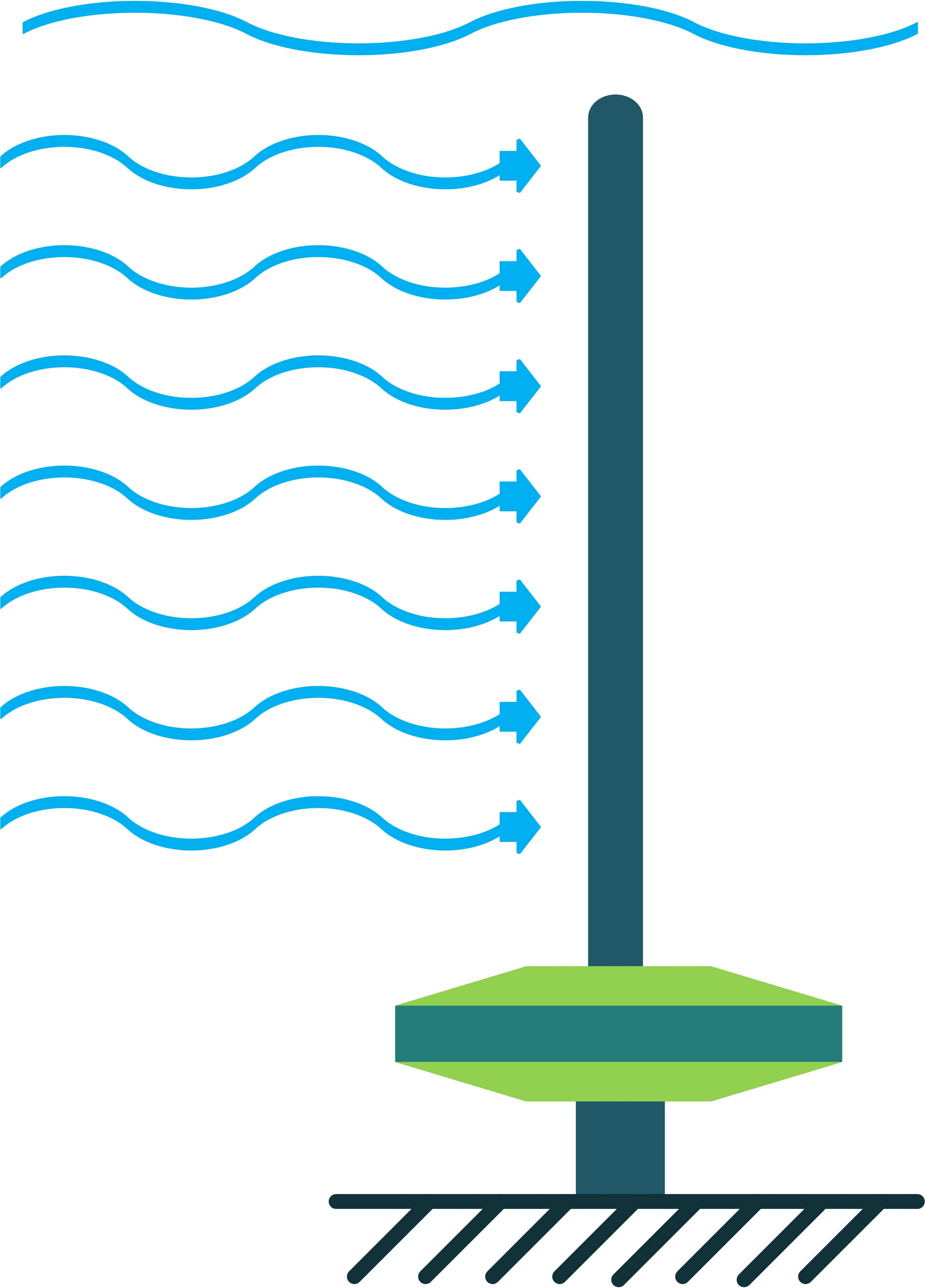
To employ piezoelectric energy harvesters to extract power from ocean water currents, the vibration in the water can be converted to electricity. To do so, the piezoelectric energy harvester should be placed in the current stream and be coupled with flow-induced vibration. Vortex-Induced Vibrations (VIV) and Self-Excited Vibrations (SEV) are the two significant flow-induced vibrations that are exploited by piezoelectric energy harvesters [21][22][45,46].
To create VIV, a bluff body is located in a water stream, and depending on the characteristics of the bluff body, vortices of a particular size and frequency appear. If, then, the piezoelectric energy harvester is placed behind the body, the generated vortices make it oscillate. This oscillation will generate electricity based on the piezoelectric principle [21][45].
Through the use of self-excitation of flexible bodies, here most often PVDF materials, SEV-based energy harvesting can be achieved. The bodies are placed in the flow stream and, by a minute increase in flow speed, the body attains self-excitation, which can be further used for electrical energy generation [22][46].
1.6.2. Wave Motion
Waves in the oceans are generated by the association of forces, such as wind, atmospheric pressure gradients, earthquakes, gravitational attraction, and storms. Moreover, these waves need to be restored using mechanisms such as surface tension, gravity, and Coriolis force. Based on their periods, waves can be classified into seven groups: (1) Capillary waves; (2) Ultra-gravity waves; (3) Gravity waves; (4) Infra-gravity waves; (5) Long-period waves; (6) Ordinary tidal waves; and (7) Trans-tidal waves [23][47].
There are two main factors in determining how much energy a wave holds (Figure 10): wave height and the wave’s period [24][48], meaning the time taken for a wave crest to travel the distance between two wave crests. Waves with a greater height and shorter periods contain more energy. However, unlike water currents where the energy is distributed all along, the waves’ energy density diminishes by the depth and is concentrated near the surface of the ocean. Therefore, the facilities’ tip that captures the wave’s energy should be close to the surface of the ocean [25][49]. According to [3][26][11,50], piezoelectric energy harvesters from wave motion mainly consist of heaving and pitching bodies, the PVDF layer on the surface of the ocean, and fixed bodies on the ocean bottom.
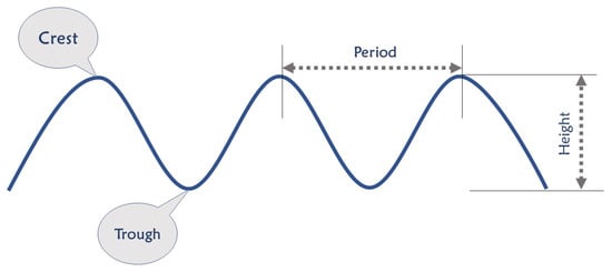
Figure 10.
Characteristics of an Oceanic Wave.
1.6.3. Wave Impact
Another feature of the ocean is the impact of the waves on the ocean structure [26][50]. Mostly, wave impacts are considered destructive forces. However, these waves’ forces on the structures can be advantageous rather than being devastating. In the case that the piezoelectric energy harvesters are placed on the surfaces that are subjected to waves’ impact, they can convert the applied pressure to electricity [3][11].
1.7. Location
Based on where the marine facilities are working, they can be categorized into three groups; onshore; nearshore; and offshore. Onshore represents regions with 10–15 m water depth, where this value is 15–25 m for nearshore, and is higher than 50 m for offshore. Figure 11 shows the different regions in the ocean [27][51].
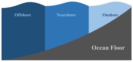
Figure 11.
Ocean Regions.
2. The ATLAS
The following comprehensive atlas of 84 designs contains information on the utilized piezoelectric materials, piezoelectric coupling modes, location, power range, energy source, and a schematic of the piezoelectric energy harvesters design in oceanic engineering. It should be noted that all the information is collected exactly from the related references without any judgments and changes. The atlas includes just the information that the research articles provided, and in the cases where there is no information in any of the atlas’s sections, the related unit is free of information. Moreover, the atlas only includes designs for which they have at least provided a simulation or fabricated and tested a prototype. The schematics are sketched in a way to help future designers simply understand the working principles of the state-of-the-art. Table 1 shows the meaning of different colors in the schematics to fully understand the concepts. Table 2, Table 3 show the atlases of cantilever beam-based, diaphragm-based, stacked-based, and cymbal-based designs, respectively. Table 1 shows the meaning of different colors in the schematics to fully understand the concepts. Table 2, Table 3 show the atlases of cantilever beam-based, diaphragm-based, stacked-based, and cymbal-based designs, respectively.
Table 1.
Meaning of each color in the atlas.
| Color | Meaning |
|---|---|
| Year and Reference | Material | Coupling Mode | Location | Power Density (W/m | 3 | ) | Energy Source | Schematics |
|---|
Table 3.
Atlas of diaphragm-based piezoelectric energy harvesters.
| Year and Reference | Material | Coupling Mode |
|---|
Table 4.
Atlas of stacked-based piezoelectric energy harvesters.
| Year and Reference | Material | Location | Power Density (W/m | 3 | ) | Coupling Mode | Location | Power Density (W/m | Energy Source | 3) | Schematics | |||
|---|---|---|---|---|---|---|---|---|---|---|---|---|---|---|
 |
||||||||||||||
| Energy Source | Schematics | |||||||||||||
| 1987 [ | Buoy | |||||||||||||
| 28] | 1987 [52] | PVDF | 3-1 | Onshore | - | Wave Motion | ||||||||
| 2010 [101] | 2010 [123] | PVDF | 3-1 | 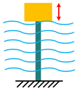 |
- | 1.90 × 10 | −2 | Water Current |  |
|||||
| 2010 [110] | PZT | 3-3 | - | 25.26 | Water Current | 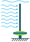  |
||||||||
| 1987 [ | Magnet | |||||||||||||
| 29] | 1987 [53] | PVDF | ||||||||||||
| 2011 | 3-3 | [102] | - | 2011 [- | Wave Motion | 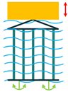 |
124] | PZT | 1-5 | - | 7.25 × 10 | −5 |  |
Piezoelectric Layer |
| Water Current |  |
2001 [30] | 2001 [54] | PVDF | 3-1 | - | - | |||||||
| 2013 [103] | 2013 [125 | Water Current | ] | PZT | - | Offshore | 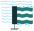 |
0.34 | Water Current | 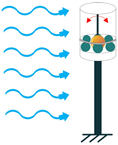 |
 |
Water | ||
| 2013 | The Other Colors | Non-Piezoelectric Material |
Table 2.
Atlas of cantilever beam-based piezoelectric energy harvesters.
| 2004 | ||||||||||||
| [ | ||||||||||||
| 31] | 2004 [55] | PVDF | 3-1 | [ | - | - | 104 | Water Current | 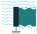 |
|||
| ] | 2013 [126] | PZT | - | Offshore | - | Wave Motion | 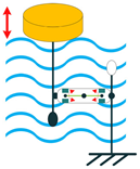 |
2004 [31] | 2004 [55] | |||
| 2013 [ | PZT | 105 | 3-1 | - | ] | 2013 [12770.00 | ]Water Current |  |
||||
| PZT | - | Offshore | - | Wave Motion | 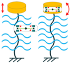 |
2007 [32] | 2007 [25] | |||||
| 2018 | PVDF | [106] | 3-1 | 2018 [Onshore | - | 128Water Current | 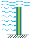 |
|||||
| ] | PZT | 3-3 | - | - | Water Current | 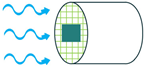 |
2009 [33] | 2009 [56] | - | - | ||
| 2019 | Offshore | [107] | 1.64 | 2019 [ | Wave Motion | 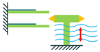 |
||||||
| 129] | PVDF | - | 2010 [34] | 2010 [57] | PVDF | 3-3 | Offshore | 15.00 | Water Current | 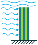 |
||
| 2011 [35] | 2011 [58] | PVDF | - | Offshore | 4.00 × 10 | −3 | Water Current | 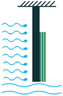 |
||||
| 2012 [36] | 2012 [59 | [37] | ,60] | PVDF | - | Offshore | 0.42 | Wave Motion- Water Current | 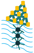 |
|||
| 2012 [38] | 2012 [61] | - | - | - | 1.56 × 10 | −4 | Water Current | 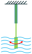 |
||||
| 2012 [39] | 2012 [62] | PZT | 3-1 | Onshore | 0.17 | Wave Motion | 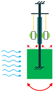 |
|||||
| 2013 [40] | 2013 [63] | PZT | 3-3 | - | 0.84 | Water Current |  |
|||||
| 2013 [41] | 2013 [64] | PZT | - | - | 366.00 | Wave Motion | 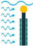 |
|||||
| 2014 [42] | 2014 [65] | PZT | - | Offshore | 75.00 | Wave Motion |  |
|||||
| 2014 [43] | 2014 [66] | PZT | 3-3 | - | 4.74 | Wave Motion | 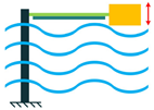 |
|||||
| 2014 [44] | 2014 [67] | PVDF | 3-1 | - | - | Water Current |  |
|||||
| 2015 [45] | 2015 [68] | MFC | 3-1 | - | 1.16 × 10 | −2 | Water Current | 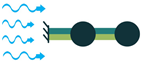 |
||||
| 2015 [46] | 2015 [69] | PZT | 3-1 | - | 2.24 × 10 | −2 | Water Current | 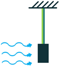 |
||||
| 2015 [47] | 2015 [70] | PZT | - | - | - | Water Current |  |
|||||
| 2015 [48] | 2015 [71] | PVDF | - | - | - | Water Current |  |
|||||
| 2015 [49] | 2015 [72] | PVDF | 3-1 | - | 1.65 × 10 | −4 | Water Current | 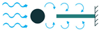 |
||||
| 2015 [50] | 2015 [73] | PZT | - | Near/Offshore | 1.27 | Wave Motion |  |
|||||
| 2015 [51] | 2015 [74] | - | - | Nearshore | 3.50 × 10 | −10 | Wave Motion |  |
||||
| 2015 [52] | 2015 [75] | MFC | - | - | 6.10 × 10 | −3 | Water Current |  |
||||
| 2016 [53] | 2016 [76] | |||||||||||
| 2021 [111] | PZT | - | - | 20.38 | Water Current | 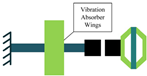 |
PZT | 3-1 | - | 17.31 | Water Current |  |
| 2016 [54] | 2016 [77] | PZT | 3-3 | Near/Offshore | 206.00 | Wave Motion |  |
|||||
| 55] | 2016 [78] | PVDF | - | - | 0.58 | Water Current | 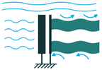 |
|||||
| - | 2016 [55] | 2016 [78] | PZT | - | - | 0.58 | Water Current |  |
||||
| 2016 [56] | 2016 [79] | PVDF | 3-1 | Near/Offshore | - | Wave Motion |  |
|||||
| 2017 [57] | 2017 [80] | PVDF | 3-1 | Near/Offshore | 2.60 × 10 | −12 | Water Current | 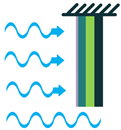 |
||||
| 2017 [58] | 2017 [81] | PZT | - | - | 1.40 | Water Current | 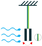 |
|||||
| 2017 [59] | 2017 [82] | PZT | - | - | 1.59 × 10 | 4 | Wave Motion | 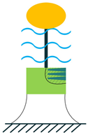 |
||||
| 5.68 × 10 | −22016 [ | 2017 [60] | 2017 [83] | PZT | - | - | 143.54 | Wave Motion | 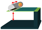 |
|||
| 2017 [61] | 2017 [84] | PZT | 3-3 | On/Near/Offshore | 260.00 | Wave Motion | 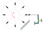 |
|||||
| 2017 [62][63] | 2017 [85,86] | PZT | 3-1 | - | 3.50 × 10 | −8 | Water Current | 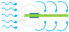 |
||||
| 2018 [64] | 2018 [87] | PZT | 3-1 | - | - | Wave Motion |  |
|||||
| 2018 [65] | 2018 [88] | PZT | - | Offshore | 10.34 × 10 | 3 | Wave Motion |  |
||||
| 2018 [66] | 2018 [89] | - | 3-3 | - | 2.40 × 10 | 3 | Wave Motion |  |
||||
| 2018 [67] | 2018 [90] | MFC | 3-1 | - | - | Water Current |  |
|||||
| 2018 [68] | 2018 [91] | - | - | - | 2.56 | Water Current |  |
|||||
| 2019 [69] | 2019 [92] | - | - | - | - | Wave Motion |  |
|||||
| 2019 [70] | 2019 [93] | PZT | 3-3 & 1-5 | - | 0.14 | Water Current |  |
|||||
| 2019 [71] | 2019 [94] | PZT | 3-3 | Offshore | 477.00 | Wave Motion | 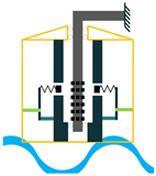 |
|||||
| 2019 [72] | 2019 [95] | PZT | 3-1 | - | - | - |  |
|||||
| 2019 [73] | 2019 [96] | PZT | - | Nearshore | 1.06 × 10 | 4 | Wave Motion |  |
||||
| 2019 [74] | 2019 [24] | - | 3-1 | Onshore | - | Wave Impact | 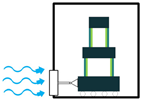 |
|||||
| 2019 [75] | 2019 [97] | PVDF | 3-1 | Offshore | 2.00 × 10 | −7 | Wave Motion |  |
||||
| 2019 [76] | 2019 [98] | - | - | - | - | Water Current |  |
|||||
| 2019 [77] | 2019 [99] | MFC | - | - | 7.58 × 10 | −9 | Water Current | 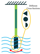 |
||||
| 2019 [78] | 2019 [100] | MFC | - | - | - | Water Current | 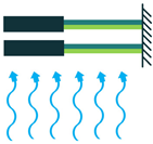 |
|||||
| 2019 [79] | 2019 [101] | PZT | - | - | - | Water Current | 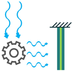 |
|||||
| 2019 [80] | 2019 [102] | PZT | PZT | 3-1 | - | 7.34 × 10 | −2 | Water Current |  |
|||
| Wave Motion | - | Offshore | 140.00 | Wave Motion |  |
|||||||
| 2020 [81] | 2020 [103] | PVDF | - | - | - | Water Current | 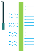 |
|||||
| 2020 [82] | 2020 [104 | 2020 [83] | 2020 [105] | MFC | - | - | - | Water Current | 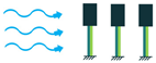 |
|||
| 2020 [84] | 2020 [106] | PZT | - | - | - | Wave Motion | 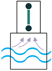 |
|||||
| 2020 [85] | 2020 [107] | PVDF | - | - | - | Water Current | 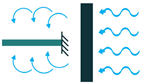 |
|||||
| 2020 [86] | 2020 [108] | PZT | - | - | 5.74 × 10 | −8 | Water Current |  |
||||
| 2021 [87] | 2021 [109] | - | - | - | 12.90 | Wave Motion |  |
|||||
 |
] | 2021 [88] | 2021 [110] | PZT | - | - | 8.42 × 10 | −4 | Water Current | 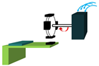 |
||
| 2021 [89] | 2021 [111] | PZT/PVDF | - | Near/Offshore | 10.50 × 10 | 2 | Wave Motion | 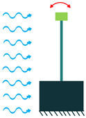 |
||||
| 2021 [90] | 2021 [112] | MFC | 3-1 | - | 10.74 × 10 | 2 | Water Current | 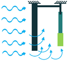 |
||||
| 2021 [91] | 2021 [113] | PVDF | 3-1 | - | - | Wave Motion |  |
|||||
| 2021 [92] | 2021 [114] | PZT | - | - | 3.58 × 10 | −2 | Water Current | 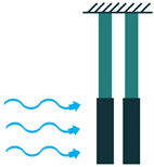 |
||||
| 2021 [93] | 2021 [115] | - | - | - | 3.20 × 10 | −3 | Wave Motion |  |
||||
| 2021 [94] | 2021 [116] | PZT | - | - | 1.63 | Wave Motion |  |
|||||
| 2021 [95] | 2021 [117] | - | - | - | - | Wave Motion |  |
|||||
| 2021 [96] | 2021 [118] | PZT/MFC | - | - | 62.00 × 10 | 3 | Wave Motion |  |
||||
| 2021 [97] | 2021 [119] | PZT | - | Offshore | - | Wave Motion |  |
|||||
| 2021 [98] | 2021 [120] | PZT | - | - | - | Wave Motion | 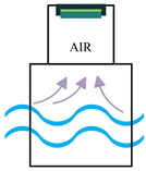 |
|||||
| 2021 [99] | 2021 [121] | - | - | Nearshore | - | Wave Motion |  |
|||||
| 2021 [100] | 2021 [122] | MFC | 3-3 | - | 8.50 × 10 | −3 | Wave Motion |  |
| Year and Reference |
|---|
|
Year and Reference |
| Material |
|---|
Material |
| Coupling Mode |
|---|
Coupling Mode |
| Location |
|---|
Location |
| Power Density (W/m | 3 | ) |
|---|
Power Density (W/m | 3 | ) |
| Energy Source |
|---|
Energy Source |
| Schematics |
|---|
Schematics |
| Wave Motion |
 |
|
2013 [50] |
PVDF |
3-3 |
- |
- |
Wave Impact |
|
|
2017 [130] |
PZT |
- |
Offshore |
600.00 |
Wave Impact |
|
|
2021 [131] |
PZT |
- |
- |
- |
Wave Motion |
|

| 2013 [50] | PVDF | 3-3 | - | - | Wave Impact | 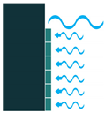 |
| 2017 [108] | PZT | - | Offshore | 600.00 | Wave Impact | 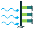 |
| 2021 [109] | PZT | - | - | - |
Table 5. Atlas of cymbal-based piezoelectric energy harvesters.
Atlas of cymbal-based piezoelectric energy harvesters.
|
Year and Reference |
Material |
Coupling Mode |
Location |
Power Density (W/m3) |
Energy Source |
Schematics |
|
2010 [132] |
PZT |
3-3 |
- |
25.26 |
Water Current |
|
|
2021 [133] |
PZT |
- |
- |
20.38 |
Water Current |
|