Zone refining is a technology of deeply purifying metals. Its essence is to use the difference in solubility of impurity elements in the solid and molten state of the main metal to precipitate the impurities or change the distribution of the impurity elements. It provides an effective and easy method for preparing high-purity metals.
- zone refining
- high-purity metals
- purification
1. Introduction
High-purity metals (99.999% (5N) or higher) are widely used in modern electronic information, aerospace, defense. The development trend of modern science and technology requires high-purity or ultra-high-purity of metals, because some important characteristics of metals are affected by the type and amount of impurities in the matrix, and some characteristics are even masked by trace elements [1].
Metals are often purified by vacuum distillation technology [2], ion exchange technology [3], extraction technology [4], electrolytic refining technology [5], zone refining technology [6], and other single or combined technologies. Among them, the zone refining technology has a wide range of applications; in addition, it is simple and easy to control, has no pollution, has a high product purity, and is suitable for the final stage of preparing high-purity metals.
2. Zone Refining Mechanism
2.1. Basic Principles
The distribution of impurity elements in the solid and liquid phase of the bulk metal melt is determined by the thermodynamic properties of the system. Impurities exist as solid solutions in the main metal. Solid solution is generally due to the presence of metal B atoms in the crystal lattice of metal
A
, thereby forming a solid solution. Due to the presence of trace impurities, the melting point of the metal may decrease or increase. The extent to which the melting point decreases or increases depends on the content of impurities. Decreasing the melting point causes the solid solution to change from the molten state to the solid state, and the impurities migrate from the solid phase to the liquid phase. When the melting point increases, the opposite is true, and the impurities migrate from the liquid phase to the solid phase. For the binary system composed of
A
and
B
(the metal
A
contains impurities
B), there is the following relationship [1][7][8]:
), there is the following relationship [1,19,20]:
∆Tf=R(T0f)2∆Hf AxB1[1−xB2xB1].
In the formula, “1” represents the molten phase, “2” represents the solid solution phase; xA1 and xB1 are the concentrations of metal A and impurity B before the change, while xA2 and xB2 are the concentrations of A and B after the change; ΔH¯¯¯fA is the heat of dissolution when 1 mol A melts into the solution from a solid solution state, and its value is positive. Due to the low impurity content, it can be regarded as a constant; T0f is the melting point of pure A; Tf is the melting point of the solid solution at the mole fraction of xA2; ΔTf=T0f−Tf is the melting point change value; R is the gas constant, and the value is 8.314.
k0=xB2xB1.
If k0 < 1, that is xB1 > xB2; then, xA1 < xA2, and the concentration of A in the solid phase is greater than the concentration of A in the liquid phase. When ΔTf
> 0, the melting point rises, as shown in Figure 1b. If k0 > 1, that is, xB1 < xB2; then, xA1 > xA2, and the concentration of A in the solid phase is smaller than the concentration of A in the liquid phase. When ΔTf < 0, the melting point drops, as shown in Figure 1a. In Figure 1, the upper part is the molten liquid zone; the middle is the solid–liquid two-phase equilibrium zone; the lower part is the solid phase zone.
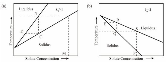
Figure 1. Binary system phase diagram; (a) k0 > 1; (b) k0 < 1.
 In the case of k0 < 1 (see Figure 1b), the solid solution containing impurities at the phase point P is heated to the molten state S and then cooled to the temperature T; the first solid phase point to condense is Q, and the impurity content is reduced compared to the phase point P. Then, the solid phase at the phase point Q is heated and melted until it reaches the phase point R, after which it is condensed, and the impurity content in the obtained solid at the phase point E is reduced again, and the heating is repeated with condensation, the impurity content in the solid phase is continuously reduced to achieve the purpose of purifying metals, but the opposite is true for k0 > 1.
2.2. Analysis of Changes in Impurities during Zone Refining
The specific process of zone refining is shown in
a. The metal materials to be purified are placed in the tubular furnace; then, install a movable heating ring outside the tube (high frequency heating ring can be used). When using multi-melting zone refining, the advantages of zone refining can be seen. As shown in
b, a series of closely spaced heaters are used to melt into multiple melting zones in the ingot; after multiple zone refining, the impurity concentration distribution reaches a steady state or limits distribution.
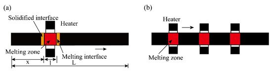
Figure 2.
Specific process of zone refining; (
a
) Single-pass zone refining; (
b
) Multi-pass melting zone refining.
3. Influencing Factors and Optimization of Zone Refining
Since Pfann [9] published the pioneering work of zone refining, domestic and foreign scholars have conducted a series of research and discussion on the influencing factors of zone refining from a practical and theoretical perspective. These factors are mainly equilibrium distribution coefficient, zone refining rate, melting zone width, diffusion layer thickness, and zone refining times.
Since Pfann [22] published the pioneering work of zone refining, domestic and foreign scholars have conducted a series of research and discussion on the influencing factors of zone refining from a practical and theoretical perspective. These factors are mainly equilibrium distribution coefficient, zone refining rate, melting zone width, diffusion layer thickness, and zone refining times.
3.1. Balanced Distribution Coefficient
The equilibrium distribution coefficient k0 is not fixed, so the effective distribution coefficient (keff) is introduced to improve the zone refining efficiency. The simplest method is to optimize keff. The BPS equation is as follows [25,26]:
3.1. Balanced Distribution Coefficient
keff=k0/[k0+(1−k0)e−fΔ/D].
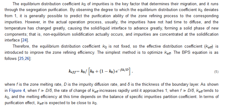 where f is the zone melting rate, D is the impurity diffusion rate, and δ is the thickness of the boundary layer. As shown in Figure 4, when f ≫ D/δ, the rate of change of keff increases rapidly until it approaches 1; when f ≫ D/δ, keff tends to k0, and the melting efficiency at this time depends on the balance of specific impurities partition coefficient. In terms of purification effect, keff is expected to be close to k0.
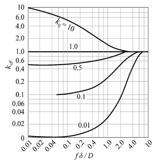
 Figure 4. Relationship between keff and fδ/D.
3.2. Zone Refining Rate
The selection of the moving speed of the melting zone (that is, the zone refining rate) directly affects the purification efficiency, which is related to the production cost. Therefore, in the purification process, it is necessary to formulate an appropriate rate according to the characteristics of the material itself. The choice of the optimal refining rate is to strike a balance between the formation of single crystals and the reduction of the degree of segregation [10].
The selection of the moving speed of the melting zone (that is, the zone refining rate) directly affects the purification efficiency, which is related to the production cost. Therefore, in the purification process, it is necessary to formulate an appropriate rate according to the characteristics of the material itself. The choice of the optimal refining rate is to strike a balance between the formation of single crystals and the reduction of the degree of segregation [32].
3.3. Length of Melting Zone
The length of the melting zone is affected by many factors, such as thermal field, zone refining speed, crucible thermal conductivity, etc. In zone refining, the purity of the product obtained in the narrow melting zone is higher than that in the wider melting zone, but the impurity concentration of the narrow melting zone increases faster, making it difficult to remove impurities in the melting zone, which must be compensated by extending the purification time [11].
The length of the melting zone is affected by many factors, such as thermal field, zone refining speed, crucible thermal conductivity, etc. In zone refining, the purity of the product obtained in the narrow melting zone is higher than that in the wider melting zone, but the impurity concentration of the narrow melting zone increases faster, making it difficult to remove impurities in the melting zone, which must be compensated by extending the purification time [33].
3.4. Zone Refining Scans
The zone refining process needs to be repeated many times. As the number of times increases, the purification effect also increases, but after a certain pass zone melting, the impurity concentration distribution is close to the “limit distribution”, as shown in
.
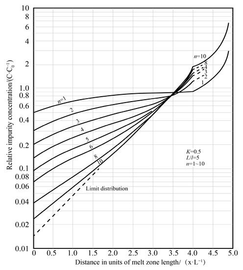
Figure 5. Relationship between impurity concentration and number of zone refining passes [12].
Relationship between impurity concentration and number of zone refining passes [35].
3.5. Application of Current in Impurity Transmission
Applying a current field during the refining process (see
) can improve the segregation of impurities at the solidification interface through electromigration.
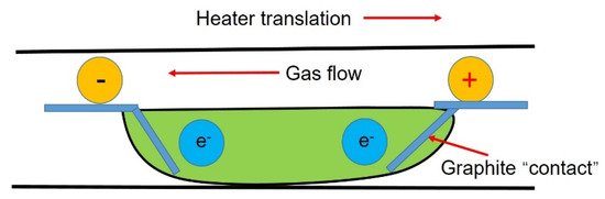
Figure 7.
Schematic diagram of the zone refining system under applied current.
3.6. Inclination
During the refining process in the horizontal area, the longitudinal section of the ingot will become tapered due to the mass transfer and even cause the melt to overflow. To avoid this phenomenon, the crucible should be inclined at an angle
θ
relative to the horizontal direction.
4. Types of Zone Refining
Based on the same principle, there are various zone refining technologies. There are two main types, refining in the suspension area and refining in the horizontal area, as shown in
.
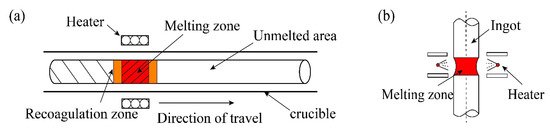
Figure 8.
(
a
) Horizontal zone refining technology; (
b
) Suspended zone refining technology.
The emergence of refining in the suspended area has greatly promoted the study of refractory metals. This method can not only effectively remove volatile metals and gas impurities in refractory metals, as well as avoid secondary pollution of metals in the refining process, but also effectively control the metal melt flow [13].
The emergence of refining in the suspended area has greatly promoted the study of refractory metals. This method can not only effectively remove volatile metals and gas impurities in refractory metals, as well as avoid secondary pollution of metals in the refining process, but also effectively control the metal melt flow [43].
lists the differences between the two methods.
Table 4. Differences in zone refining technology [13].
| Category | Heating Method | Advantage | Disadvantage | Scale |
|---|---|---|---|---|
| Floating zone refining | Electron beam heating, induction heating, plasma heating, light heating | The ingot does not touch the container, so the product purity is high, and the equipment occupies a small space. | The melting zone is supported by surface tension, so controlling the shape and stability of the melting zone is the key, and the output is low. | Small batch |
| Horizontal zone refining | Induction heating, resistance heating | Simple equipment, continuous purification of multiple melting zones, easy loading and unloading of materials, easy identification of interfaces, and the total length of ingots can be increased or decreased as needed | Large footprint | Batch |