Reduced graphene oxide (rGO) is a reduced form of graphene oxide used extensively in gas sensing applications. However, in its pristine form, graphene has some shortages and thus, it is generally utilized in combination with other metal oxides to improve gas sensing capabilities. There are different ways of adding rGO to different metal oxides with various morphologies. This study focuses on rGO-loaded metal oxide nanofiber (NF) synthesized using an electrospinning method. Different amounts of rGO were added to the metal oxide precursors, and after electrospinning, the gas response is enhanced through different sensing mechanisms.
- gas sensor
- reduced graphene oxide
- rGO-loading
- metal oxide
- sensing mechanism
1. Introduction
Metal oxide gas sensors are used to sense various toxic gases and vapors [1][2] in many areas [3]. These sensors are quite popular owing to their low preparation costs, high sensitivity, fast dynamics, high stability, simple operation, and small size [4]. The general gas sensing mechanism of metal oxide gas sensors stems from the modulation of electrical resistance in the presence of target gases [5]. In these sensors, the sensing layer is exposed directly to the gas. The interaction between the target gas and sensing layer modulates the electrical resistance of the gas sensor, resulting in the generation of a sensing signal. This conductivity change is due to variations in the width of the electron depletion layer across the exposed area of the sensing layer [6]. Various strategies can be used to enhance the gas sensing characteristics of metal oxide-based gas sensors, such as UV light activation [7], fabrication of p-n, p-p and n-n heterojunctions [8], noble metal decoration [9],surface engineering, and the generation of structural defects [10]. Thus far, different morphologies of metal oxides, such as nanowires [11], nanotubes [12], nanorods [13], nanobelts [14], nanofibers (NFs), nanosheets [15], and hierarchical structures [16], have been used in gas sensing studies. This is because gas adsorption on the surface of gas sensing relates directly to the surface area of gas sensors and higher adsorption of gas means higher sensing signal. Thus, several studies have attempted to synthesize morphologies with a high surface area to increase the sensing performance of gas sensors. In addition, a porous morphology [17] and hollow structures [18][19] can be other useful techniques to increase the gas sensing properties. Therefore, metal oxide NFs are highly popular for sensing studies because of a very high surface area results from the one-dimensional morphology and the presence of nanograins on their surfaces, as shown in
Metal oxide gas sensors are used to sense various toxic gases and vapors [1,2] in many areas [3]. These sensors are quite popular owing to their low preparation costs, high sensitivity, fast dynamics, high stability, simple operation, and small size [4]. The general gas sensing mechanism of metal oxide gas sensors stems from the modulation of electrical resistance in the presence of target gases [5]. In these sensors, the sensing layer is exposed directly to the gas. The interaction between the target gas and sensing layer modulates the electrical resistance of the gas sensor, resulting in the generation of a sensing signal. This conductivity change is due to variations in the width of the electron depletion layer across the exposed area of the sensing layer [6]. Various strategies can be used to enhance the gas sensing characteristics of metal oxide-based gas sensors, such as UV light activation [7], fabrication of p-n, p-p and n-n heterojunctions [8], noble metal decoration [9],surface engineering, and the generation of structural defects [10]. Thus far, different morphologies of metal oxides, such as nanowires [11], nanotubes [12], nanorods [13], nanobelts [14], nanofibers (NFs), nanosheets [15], and hierarchical structures [16], have been used in gas sensing studies. This is because gas adsorption on the surface of gas sensing relates directly to the surface area of gas sensors and higher adsorption of gas means higher sensing signal. Thus, several studies have attempted to synthesize morphologies with a high surface area to increase the sensing performance of gas sensors. In addition, a porous morphology [17] and hollow structures [18,19] can be other useful techniques to increase the gas sensing properties. Therefore, metal oxide NFs are highly popular for sensing studies because of a very high surface area results from the one-dimensional morphology and the presence of nanograins on their surfaces, as shown in
. The generation of depletion layers on nanograins causes the development of potential barriers, which will be modulated during exposure to the target gases, contributing to the sensing signal generation.
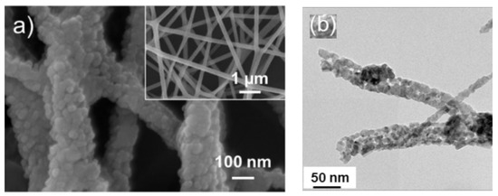
Figure 1.
a) FE-SEM image of ZnO electrospun NFs. The inset indicates high magnification image [20] (
b
2
3
4composite NFs [21].
Another advantage of NFs is their ease of preparation using a facile electrospinning technique. In general, the electrospinning technique can be used to fabricate continuous fibers with the possibility of control over the fiber diameter [22]. In addition, different NFs, such as porous NFs [23], core-shell NFs [24][25], and complex NFs [26], can be easily synthesized by electrospinning. Furthermore, NFs with controllable alignment can be produced by modifying the electrospinning [27]. Electrospinning also can be used for the mass production of NFs because of the easy handling, possibility of control of the diameter, low cost, simple operation, and high reproducibility [28]. Briefly, the features of electrospun fibers can be controlled by electrospinning parameters, including the solution variables (e.g., surface tension, viscosity, and conductivity), operating variables (e.g., applied voltage, spinning distance, and solution flow rate), and ambient variables (e.g., humidity and temperature) [29].Li et al. [30] (
Another advantage of NFs is their ease of preparation using a facile electrospinning technique. In general, the electrospinning technique can be used to fabricate continuous fibers with the possibility of control over the fiber diameter [22]. In addition, different NFs, such as porous NFs [23], core-shell NFs [24,25], and complex NFs [26], can be easily synthesized by electrospinning. Furthermore, NFs with controllable alignment can be produced by modifying the electrospinning [27]. Electrospinning also can be used for the mass production of NFs because of the easy handling, possibility of control of the diameter, low cost, simple operation, and high reproducibility [28]. Briefly, the features of electrospun fibers can be controlled by electrospinning parameters, including the solution variables (e.g., surface tension, viscosity, and conductivity), operating variables (e.g., applied voltage, spinning distance, and solution flow rate), and ambient variables (e.g., humidity and temperature) [29].Li et al. [30] (
Figure 2) and Xue et al. [31] reviewed these factors, so this review paper does not discuss them further.
) and Xue et al. [31] reviewed these factors, so this review paper does not discuss them further.
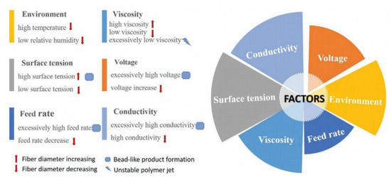
Figure 2. Factors affecting fiber formation during electrospinning [30].
Figure 3 shows the major components of electrospinning include a syringe pump, spinneret, conductive collector, and power supply. The electrospinning technique can be described as follows: (1) charging of the liquid droplet and the formation of a Taylor cone, (2) formation of the charged jet, (3) thinning of the jet by the applied voltage, and (4) collection and solidification of the jet on a grounded collector. A Taylor cone is formed owing to surface tension and the applied electric field, from which a charged jet is ejected. The ejected jet was solidified quickly, resulting in the collection of solid fibers on the collector [32][33].
shows the major components of electrospinning include a syringe pump, spinneret, conductive collector, and power supply. The electrospinning technique can be described as follows: (1) charging of the liquid droplet and the formation of a Taylor cone, (2) formation of the charged jet, (3) thinning of the jet by the applied voltage, and (4) collection and solidification of the jet on a grounded collector. A Taylor cone is formed owing to surface tension and the applied electric field, from which a charged jet is ejected. The ejected jet was solidified quickly, resulting in the collection of solid fibers on the collector [32,33].
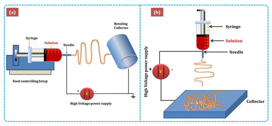
Figure 3.
a
b)vertical setups of electrospinning [34].
2. Graphene, Graphene Oxide, and Reduced Graphene Oxide
Graphene is a single-layer comprised of sp
2
carbon atoms that can be used as a gas sensor owing to its high charge carrier mobility (200,000 cm
2
V
−1
s
−1
), high mechanical stiffness, high environmental compatibility, and huge surface area (2630 m
2
g
−1) [35][36]. Schedin et al. [37] introduced the first graphene gas sensor in 2007. Because atoms in a single layer of graphene can be considered surface atoms, graphene can interact with even a single molecule [37]. Even though nowadays pristine graphene can be synthesized on a large scale [38] with good water solubility [39][40], it can be easily agglomerated in solution due to surface interactions [41]. Moreover, graphene has no bandgap or functional groups, limiting its gas sensors applications, particularly in the pristine form [42]. Therefore, reduced graphene oxide (rGO), which is synthesized by the reduction of graphene oxide (GO), is a better choice for gas sensing applications because it has many functional groups and defects [43]. GO has also been used for gas sensing studies [44]. On the other hand, GO has very high resistance due to the presence of alkoxy (C-O-C), hydroxyl (-OH), carboxylic acid (-COOH), carbonyl (C=O), and other oxygen-based functional groups [45][46]. rGO has more defects and dangling bonds than graphite, resulting in better sensing properties [47]. GO is widely prepared using either Hummers [48] or Brodie [49] methods. In these methods, differences are in both the acid used (nitric or sulfuric acid), and the type of salt used (potassium chlorate or potassium permanganate). By subsequent reduction of GO, rGO can be obtained. In fact, rGO can be prepared easily from GO by chemical reduction, thermal reduction, and UV light reduction [50].
) [35,36]. Schedin et al. [37] introduced the first graphene gas sensor in 2007. Because atoms in a single layer of graphene can be considered surface atoms, graphene can interact with even a single molecule [37]. Even though nowadays pristine graphene can be synthesized on a large scale [38] with good water solubility [39,40], it can be easily agglomerated in solution due to surface interactions [41]. Moreover, graphene has no bandgap or functional groups, limiting its gas sensors applications, particularly in the pristine form [42]. Therefore, reduced graphene oxide (rGO), which is synthesized by the reduction of graphene oxide (GO), is a better choice for gas sensing applications because it has many functional groups and defects [43]. GO has also been used for gas sensing studies [44]. On the other hand, GO has very high resistance due to the presence of alkoxy (C-O-C), hydroxyl (-OH), carboxylic acid (-COOH), carbonyl (C=O), and other oxygen-based functional groups [45,46]. rGO has more defects and dangling bonds than graphite, resulting in better sensing properties [47]. GO is widely prepared using either Hummers [48] or Brodie [49] methods. In these methods, differences are in both the acid used (nitric or sulfuric acid), and the type of salt used (potassium chlorate or potassium permanganate). By subsequent reduction of GO, rGO can be obtained. In fact, rGO can be prepared easily from GO by chemical reduction, thermal reduction, and UV light reduction [50].
Figure 4 shows the structure and preparation of GO and rGO [44].
shows the structure and preparation of GO and rGO [44].
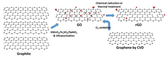
Figure 4. Structure and preparation of GO and rGO [44].
Furthermore, rGO has high thermal stability, and the total weight loss of rGO was reported to be only 11% up to 800 °C, which was attributed to the absence of most oxygen functional groups. [51]. Pristine rGO gas sensors have a long response and recovery times, and incorporating rGO with metal oxides can be a good strategy to increase the sensing capabilities of rGO-based gas sensors [52]. The synthesis and properties of rGO have been reviewed comprehensively [41]. The following section explains the gas sensing capability of rGO-loaded metal oxide NFs. This paper does not discuss the combination of rGO with other materials, such as mesh fabric [53] or polymers [54][55], for gas sensing studies. Furthermore, composites of metal oxides-rGO in morphologies other than NFs are not discussed.
Furthermore, rGO has high thermal stability, and the total weight loss of rGO was reported to be only 11% up to 800 °C, which was attributed to the absence of most oxygen functional groups. [51]. Pristine rGO gas sensors have a long response and recovery times, and incorporating rGO with metal oxides can be a good strategy to increase the sensing capabilities of rGO-based gas sensors [52]. The synthesis and properties of rGO have been reviewed comprehensively [41]. The following section explains the gas sensing capability of rGO-loaded metal oxide NFs. This paper does not discuss the combination of rGO with other materials, such as mesh fabric [53] or polymers [54,55], for gas sensing studies. Furthermore, composites of metal oxides-rGO in morphologies other than NFs are not discussed.
2.1. RGO-Loaded Metal Oxides Gas Sensors
2.1.1. rGO-Loaded ZnO NFs
Zinc oxide (ZnO) is one of the most common metal oxides in the gas sensing area because of its unique properties, such as n-type conductivity, low toxicity, ease of synthesis, high availability, good thermal stability, and high mobility of electrons [56][57]. Abideen et al. [58] prepared rGO-loaded ZnO NFs for H
Zinc oxide (ZnO) is one of the most common metal oxides in the gas sensing area because of its unique properties, such as n-type conductivity, low toxicity, ease of synthesis, high availability, good thermal stability, and high mobility of electrons [56,57]. Abideen et al. [58] prepared rGO-loaded ZnO NFs for H
2
gas sensing investigations. At 400 °C, the sensor exhibited an exceptionally strong response (R
a
/R
g
) of 2542 to 10 ppm H
2
gas. The presence of rGO and a semiconductor (ZnO)-to metal (Zn) transition in a H
2
atmosphere were the main reasons behind the enhanced response to H
2
gas. They suggested that ZnO could be converted to metallic Zn in the presence of H
2
gas because of the high-sensing temperature. Owing to the differences in the work functions of rGO, ZnO, and Zn, at equilibrium, potential barriers were generated at both rGO/Zn and Zn/ZnO interfaces. ZnO was more n-type because of the flow of electrons from the Zn layer to ZnO. Accordingly, high resistance modulation occurred, contributing to the sensing signal. In addition, the potential barriers of rGO/Zn prevented the flow of electrons to rGO, which acted as a source of resistance modulation in the presence of H
2
gas.
In another similar investigation, Abideen et al. reported the effects of the rGO-loading (0.04, 0.11, 0.17, 0.44, 0.77, and 1.04 wt.%) on the NO
2 sensing response of ZnO NFs [59].
sensing response of ZnO NFs [59].
a,b shows SEM and TEM images of 0.44 wt.% rGO-loaded ZnO NFs, respectively.
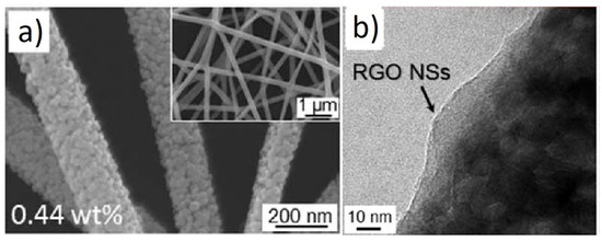
Figure 5.
a
b
Among rGO-loaded ZnO NF gas sensors, the sensor with a 0.44 wt.% rGO-loading showed an enhanced response to NO2 gas. The sensor showed a response (Ra/Rg) of ~123 to 5 ppm NO2 gas at 400 °C.The boundaries between the nanograins acted as a source of resistance modulation caused by the generation of potential barriers resulting from oxygen adsorption. After introducing NO2 gas, the height of the potential barriers increased across the grain boundaries, leading to the sensor signal (Figure 6a).
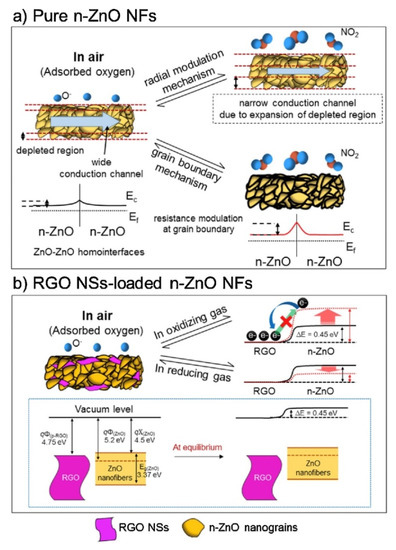
Figure 6.
2
a
b
In the rGO/ZnO heterojunctions, Ohmic contact was generated (
b), acting as a non-rectifying barrier to charge transfer, which affected the sensing behavior. In a NO
2
atmosphere, the resistance of the gas sensor was increased because of the abstraction of more electrons. In addition, discretely distributed rGO nanosheets, which had a high surface area, played a catalytic role on NO
2
gas molecules. Other contributions were the presence of defects in rGO, which were favorable sites for the adsorption of gases.
Abideen et al. synthesized rGO-loaded ZnO NFs functionalized by Au and Pd NPs, as shown in
[60].
a–c shows typical TEM images of rGO nanosheets, ZnO NFs and Au-decorated ZnO NFs, respectively. At 400 °C, the sensors functionalized with Au and Pd showed an enhanced gas response towards CO and C
6
H
6
gases, respectively. Owing to the formation of ZnO/rGO heterojunctions, the electron depletion layer was wider in the ZnO NFs. Upon exposure to reducing gases, they interacted with oxygen species and liberated electrons, resulting in increased sensor conductivity, contributing to the sensing signal.
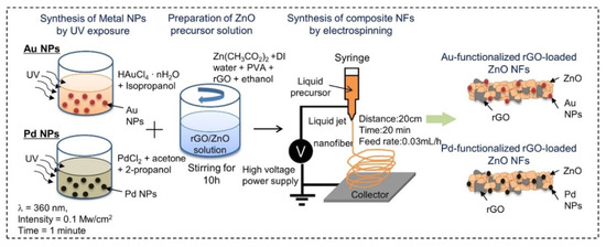
Figure 7. Preparation of Au and Pd-decorated rGO-loaded ZnO NFs [60].
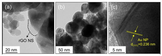
Figure 8.
a
b
c
rGO has a high surface area, many defects and functional groups, and a different work function than ZnO. These factors contributed to the sensing enhancement. The effects of noble metals were considered. In the case of electronic sensitization, oxidized Pd (PdO), which initially took electrons from ZnO, was reduced in the presence of C
6
H
6
. Accordingly, the space charge layer was relaxed by the return of electrons to the ZnO. In chemical sensitization, Au and Pd NPs acted as catalytic metals. The incoming oxygen species were adsorbed on the surface of Au or Pd, leading to the dissociation of oxygen and subsequent spillover to neighboring ZnO. This increased the initial width of the electron depletion layers, which acted as a source of resistance modulation in the presence of the target gases. Furthermore, Schottky barriers were formed in the interfaces between Au/ZnO and Pd/ZnO (
). The width of the electron depletion layer decreased because of the flow of electrons from ZnO to metal. Moreover, the width of the electron depletion layer decreased by subsequent interaction of reducing gases and the liberation of electrons, causing a large change in resistance of the gas sensor.
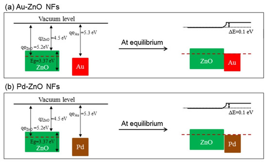
Figure 9.
a
b
The good selectivity of the Au-functionalized gas sensor to CO was attributed to the low (1.20 eV) oxidation barrier of CO on Au and the strong interaction of Au with CO gas. In addition, strong adsorption of C6H6 on Pd resulted in the strong response of the Pd-functionalized gas sensor to benzene.
2.1.2. rGO-Loaded SnO2 NFs
SnO
2 is among the most popular metal oxides for sensing studies because of its high stability, favorable bandgap, low price, and good intrinsic sensing properties [61][62]. Lee et al. [63] examined the effects of rGO-loadings (0.04–1.04 wt.%) on the NO
is among the most popular metal oxides for sensing studies because of its high stability, favorable bandgap, low price, and good intrinsic sensing properties [61,62]. Lee et al. [63] examined the effects of rGO-loadings (0.04–1.04 wt.%) on the NO
2
gas sensing properties of SnO
2
NFs produced by electrospinning. The sensor with 0.44 wt.% rGO exhibited the highest resistance and the strongest response (R
a
/R
g
) of ~100 to 5 ppm NO
2
gas at 200 °C. The pristine sensors showed a change in resistance due to the grain boundary mechanism and radial modulation, as shown in
a. For rGO-loaded sensors (
b), p-n heterojunctions were formed, generating potential barriers to the flow of electrons. The heights of these barriers were changed in the target gas atmosphere, resulting in sensing signal generation.
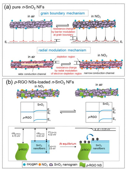
Figure 10.
2
a
2
b
2 NFs [63].
Hollow NFs are also interesting morphologies for gas sensing studies because of their higher surface areas that can interact with gas species [64]. For example, a BET surface area of hollow SnO
2
NFs composited with GO was reported to be 33.4m
2/g. In this regard, Li et al. [65] investigated rGO-loaded SnO
/g. In this regard, Li et al. [65] investigated rGO-loaded SnO
2
NFs for gas sensing studies.
shows typical SEM and TEM images of rGO-loaded SnO
2
NFs.
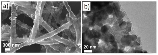
Figure 11.
a
b
2 hollow NFs [65].
p-n heterojunctions were formed between the connections owing to the intimate contact between rGO and SnO
2
. (
a). Under UV illumination (
b), SnO
2
acted as a UV absorber and a collector of generated electrons, whereas rGO acted as a photoelectron acceptor and provided many electron transport pathways. Generated electrons, as a result of UV illumination, can be adsorbed by oxygen species. The holes generated can be combined with chemisorbed oxygen, resulting in the desorption of oxygen. Thus, equilibrium is achieved under UV light. The best response could be achieved by tuning the UV light intensity. Oxidizing gases, such as NO
2
, can abstract electrons from the surface of the gas sensor. Compared to the dark condition, many more photoelectrons are captured by NO
2
gas, resulting in a stronger response to NO
2
gas. The strongest response was obtained under a 97 mW/cm
2
UV light intensity, which indicated a response of ~100% (ΔR/R
a
×100) to 5 ppm NO
2
at room temperature.
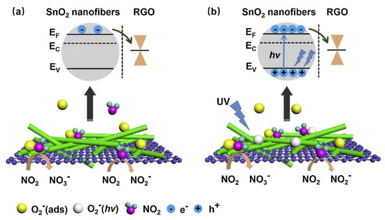
Figure 12. The sensing mechanism of rGO-loaded SnO2NFs to NO2(a) in the dark and (b) UV illumination [65].
2.1.3. rGO-Loaded α-Fe2O3 NFs
n-Type α-Fe
2
O
3 is one of the most popular oxides, with many excellent features, such as low cost and facile preparation [66]. In that study, 0.5, 1.0, and 3.0wt.% rGO-loaded α-Fe
is one of the most popular oxides, with many excellent features, such as low cost and facile preparation [68]. In that study, 0.5, 1.0, and 3.0wt.% rGO-loaded α-Fe
2
O
3
NFs with approximate diameters of 100 nm were prepared using an electrospinning technique. The response of the optimal gas sensor, namely 1wt.% rGO/α-Fe
2
O
3
NFs at 375 °C to 100ppm acetone was approximately 8.9, which was approximately 4.5 times higher than the pure α-Fe
2
O
3gas sensor [67]. The resistance of the composite sensors was lower than that of the pristine sensor, and the sensors with larger amounts of rGO showed lower conductivity. Ohmic contacts were generated because of the formation of rGO-Fe
gas sensor [69]. The resistance of the composite sensors was lower than that of the pristine sensor, and the sensors with larger amounts of rGO showed lower conductivity. Ohmic contacts were generated because of the formation of rGO-Fe
2
O
3
heterojunctions, which contributed to the sensing signal. Furthermore, defects and functional groups in rGO provided strong adsorption sites for gas molecules. In addition, the spaces between the layers of rGO nanosheets acted as an effective gas diffusion channel, which also provided more adsorption sites for gas molecules. When the amount of rGO was 3 wt.%, the surface of Fe
2
O
3
was covered further with rGO, resulting in a significant decrease in the number of gas adsorption sites of α-Fe
2
O
3
. Thus, acetone gas reacted mainly with rGO rather than α-Fe
2
O
3
NFs, leading to a low response.
Hoang et al. [68] prepared rGO-loaded (0–1.5wt.%) α-Fe
Hoang et al. [70] prepared rGO-loaded (0–1.5wt.%) α-Fe
2
O
3
NFs for sensing studies. The 1 wt.% rGO loaded sensor showed a strong response (R
a
/R
g
) of ~9.2 to 1ppm H
2
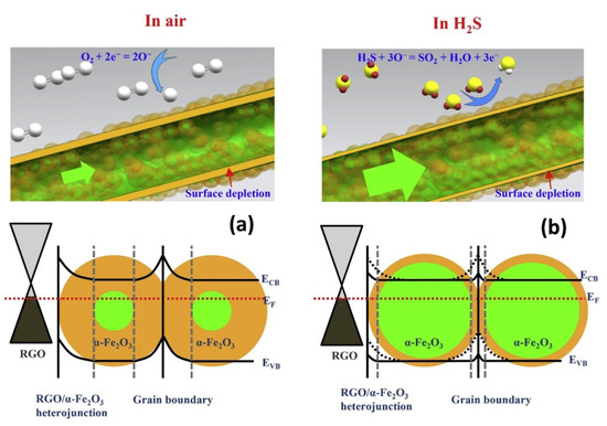
S gas at 350 °C. On the other hand, when rGO was increased, rGO nanosheets were dominant for the electron pathways, which decreased the overall sensor resistance, causing a weaker sensor response. The formation of rGO/Fe
2
O
3
heterojunctions (
), high surface area resulting from the NFs, and strong adsorption sites, such as oxygen functional groups and structural defects, also enhanced the sensor response.

