1. CO2 capture with Membrane Technologies
1.1. Basic Principles and Mechanism of Membrane Gas Separation
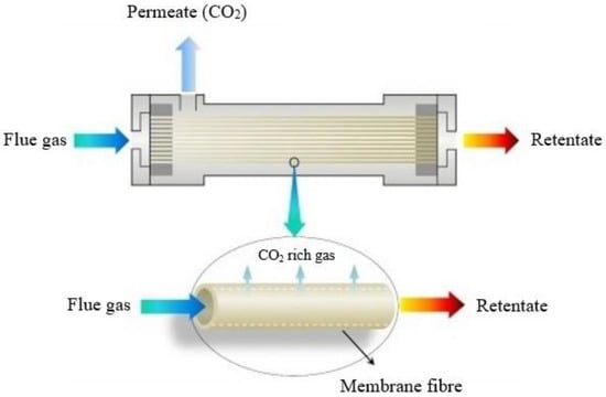
During gas separation using membrane technology, a membrane acts as a filter that allows specific molecules to permeate (e.g., CO
2) but prevents other molecules from entering the membrane (e.g., CH
4 and H
2O) (
Figure 15) due to characteristics such as gas–membrane chemical interactions or the kinetic diameter. Membrane processes, such as micro-filtration, ultra-filtration, nano-filtration and reverse osmosis, are widely used in solid–liquid separations
[1][60]; however, membrane gas separation is also attracting intensive research for carbon capture, utilization and storage (CCUS) during recent years
[2][3][10,61].
Figure 15. CO2 separation principles with the use of a membrane module.
For membranes with no permanent porosity, i.e., membranes that consist of dense polymeric materials, the most widely adopted mechanism/model for mass transport is the solution-diffusion model. According to this model, transport occurs in three steps: (1) dissolution or sorption of a gas into the membrane at the high-pressure material side, (2) diffusion of the sorbed gas through the membrane, and (3) desorption of the gas from the membrane at the low-pressure material side. The chemical potential difference between the high-pressure and low-pressure contacting phases controls the driving force, which is created through gas compression or vacuum. For ideal gas contacting phases, the gas flux across the membrane is calculated using the following equation:
where Ji is the flux across the membrane of species i (mol/m2/s); Qi is the membrane permeability for species i (mol·m/m2/s/Pa); δ is the effective membrane thickness (m); Pr and Pp are the feed/retentate high pressure and the permeate low pressure (Pa), respectively; and xi and yi are the high-pressure and low-pressure gas-phase mole fractions (mol/mol), respectively. The permeability is equal to the product of gas solubility and diffusivity in the membrane. The ratio of permeability to membrane thickness in Equation (1) is defined as the gas permeance: q ≡ 𝑄𝑖𝛿
· (mol/m2/s/Pa). Commonly, permeance is expressed in gas permeation units (GPUs), where 1 GPU = 3.35 · 10−10 (mol/m2/s/Pa).
Selectivity expresses the ability of a membrane to separate two gases. For a pair of gases, i and j, selectivity is defined as the ratio of gas permeabilities or permeances:
where component
i is the gas with the higher permeability, resulting in a selectivity greater than 1. In membrane technologies, selectivity and permeability are the most important parameters for efficient gas separation and determine the process economics; the energy (operating) cost is controlled by selectivity, whereas the membrane area (capital) cost is controlled by permeability. An increase in selectivity decreases the amount of gas that must permeate from the high-pressure feed to the low-pressure permeate to achieve the desired targets for product purity; this decreases the compression energy lost due to permeation. An increase in permeability or permeance, i.e., of the gas permeation flux per unit of driving force, reduces the area of the membrane and the capital cost that is necessary to achieve a specific feed or product flow rate
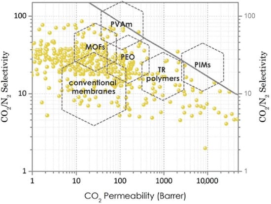
[4][5][14,62]. The Robeson correlation is an empirical correlation that presents a trade-off between permeability and selectivity of gases, and its upper boundary is usually employed to assess the performance of membrane systems (
Figure 26). To address the challenges in reducing carbon capture cost, a membrane material should be on the Robeson upper bound (or above it), i.e., in the region of high permeability/moderate selectivity
[6][7][63,64].
Figure 26. Robeson upper bound plot for gas separation membranes made from various materials (PVAm: polyvinylamine, MOFs: metal–organic frameworks, PEO: polyethylene oxide, TR: thermally rearranged polymers, PIMs: polymers of intrinsic microporosity)
[6][63].
1.2. Membrane Configurations and Process Engineering
Typical membrane configurations for separating CO
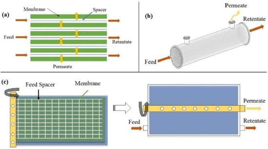
2 include hollow fiber (HF), flat-sheet (FS) and spiral-wound (SW) membranes (
Figure 37). Hollow fiber membranes, which contain hundreds or thousands of hollow fibers packed into bundles, are the most studied membrane configuration due to their high surface area per unit volume, which promotes gas transfer. However, they present drawbacks, such as fiber fouling and significant pressure drops. On the contrary, flat-sheet membranes, which are usually stacked on top of each other, present lower pressure drops and enhanced mass transfer because they employ specially designed feed spacers. In addition, they can be easily fabricated and physically or chemically cleaned. Spiral-wound membranes actually consist of flat-sheet membranes that are rolled around a collection tube
[8][9][65,66].
Figure 37. Graphic illustration of the main membrane configurations: (
a) flat-sheet membrane in cross flow, (
b) hollow fiber membrane in co-current flow, and (
c) spiral-wound membrane before and after spinning
[8][65].
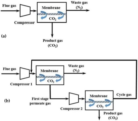
According to the employed process engineering configuration, gas separation using membranes can occur in a single-stage process with one membrane module or in a two- (or multi-)stage process with two (or more) membrane modules that are placed in series or in a parallel configuration (
Figure 48)
[10][11][67,68]. During the single-stage process (
Figure 48a), high selectivity is needed to achieve 95% purity and 90% recovery of CO
2. Consequently, it is difficult to achieve high targets using the single-stage membrane process, mainly because the purity of the final product is limited by the low CO
2 content in the feed gas and by the trade-off effect between recovery and purity. On the contrary, high purity and recovery targets are achieved more easily in the two-stage membrane process (
Figure 48b) as the gas recycling enhances the recovery of CO
2 significantly. However, the two-stage membrane process consumes more power since more compressors (or vacuum pumps) are needed, and the gas recycling increases the required membrane area. Consequently, during membrane separation with two or more stages, the main target is to reduce energy consumption and membrane area
[12][69].
Figure 48. Process engineering configurations for CO
2 capture from flue gases using membranes: (
a) single-stage membrane configuration, and (
b) two-stage membrane configuration
[12][69].
1.3. Membrane Materials
Each membrane material presents advantages and disadvantages, which are concerned with the separation performance, material cost, lifetime and other characteristics, such as chemical and thermal stability, and mechanical strength. Organic (polymeric) membranes, inorganic membranes and mixed-matrix membranes (MMMs) are the main membranes applied for post-combustion CO
2 capture
[13][14][15][70,71,72].
Among various membrane materials, polymeric materials present inherent advantages in terms of cost, variety and ease of processing. Polymers, including polyacetylene
[16][73], polyaniline
[17][74], polyamides
[18][75], polyimides
[19][76], polyetherimides
[20][77], polycarbonates
[21][78], poly(phenylene oxides)
[22][79], poly(ethylene oxides)
[23][80], polysulfones
[24][81] and cellulose acetate
[25][82], have been examined for post-combustion CO
2 capture. Generally, the solution-diffusion transport mechanism and the facilitated transport mechanism are broadly adopted as the principal mechanisms when the design of new polymers is considered. Membranes which are made from the aforementioned polymeric materials follow the solution-diffusion mechanism. In facilitated transport membranes, CO
2 transport is enhanced by the interaction between CO
2 molecules through reversible reactions (see
Section 5.5). Compared to other materials, polymeric materials can be regarded as the optimal materials due to many characteristics, such as thermal stability, mechanical strength and chemical resistance. By controlling the polymer preparation and chemical composition process, the permeability and selectivity of these membranes can be easily adjusted. In addition, polymeric membranes are one of the best options due to the development of membrane technologies in various industries, such as biogas upgrading and petrochemicals. However, CO
2 adsorption via polymer-based materials can cause swelling and plasticization problems
[26][27][15,83].
Non-polymeric materials, such as activated carbon, zeolites, silica and metal–organic frameworks (MOFs), are also emerging for CO
2 capture. These membranes are more stable than polymeric membranes and, therefore, they are strong candidates for the efficient separation of gas mixtures, especially under harsh operating conditions. However, although inorganic membranes can be used in adverse conditions, the construction and sealing of the relevant modules for applications of high temperatures are quite difficult, and the cost of production is often much higher in comparison with polymer membranes. Ceramic membranes, which usually consist of aluminum oxide (Al
2O
3), titanium oxide (TiO
2) or carbon nanotubes (CN), are a group of inorganic membranes with improved properties in terms of mechanical strength, thermal stability and chemical stability. Nonetheless, they present short operating time and low flexibility to form HF or SW membranes; as a result, their utilization in CO
2 capture is still under research
[15][27][28][72,83,92].
The limitations of membranes that are made from pure polymeric or inorganic materials prevent their widespread utilization in gas separation processes. Although pure polymeric membranes present exceptional mechanical properties, which allow their easy processing, they are limited by the trade-off effect that prevents achieving both high selectivity and permeability. Pure inorganic membranes present high selectivity or permeability, but they are thick and fragile and, thus, it is difficult to use them on a full-scale level. Aiming to overcome the aforementioned issues, the co-blending of organic and inorganic materials has been proposed to fabricate composite or mixed-matrix membranes (MMMs) with high permeability, selectivity, enhanced mechanical properties and potential for large-scale implementation. As a result, current research in membrane-based gas separation focuses mainly on the synthesis of composite membranes, which are usually fabricated via the integration of innovative inorganic materials, also known as ‘fillers’, into polymeric membranes
[29][30][93,94]. The following section presents the latest developments regarding the use of these membranes for separating CO
2.
2. State of the Art in CO2 Capture with the Use of Membrane Technologies
The application of membrane separation processes for CO
2 capture is increasingly gaining traction during the last decade. Membrane technologies are environmentally friendly, energy-efficient and easily scalable, while also presenting cost-effectiveness and design simplicity
[31][95]. As concerns carbon capture, membrane technologies are employed mainly for H
2/CO
2 separation during pre-combustion, CO
2/N
2 separation during post-combustion and O
2/N
2 separation during oxy-fuel combustion.
The most recent advances in CO
2 capture using membrane technologies principally involve employing a membrane material; the vast majority of research studies that examine membrane-based technologies for post-combustion CO
2 capture focus on the fabrication and application of novel membrane materials which selectively separate CO
2 from N
2. In most of them, a polymeric material (continuous phase) is combined with an inorganic material of micro- or nano-size (filler, dispersed phase) to form
composite membranes or mixed-matrix membranes (MMMs) with improved properties, i.e., enhanced intrinsic and surface characteristics. To achieve this, composite membranes employ a broad variety of materials, such as silica, zeolites and metal oxides
[27][32][33][34][58,83,96,97].
The fillers, which are incorporated in MMMs, can be classified as non-porous (e.g., metal oxides and silica) or porous
[35][98]. Generally, porous materials are classified into four groups
[36][37][99,100]:
- (i)
-
Inorganic materials, e.g., zeolites.
-
- (ii)
-
Carbon-based materials, e.g., carbon nanotubes and carbon molecular sieves (CMSs).
-
- (iii)
-
Organic-based materials, such as (a) porous organic frameworks (POFs), which include covalent organic frameworks (COFs), porous aromatic frameworks (PAFs), covalent organic polymers (COPs) and porous organic polymers (POPs), and (b) microporous polymers, which include polymers of intrinsic microporosity (PIM) and thermally rearranged (TR) polymers.
-
- (iv)
-
Hybrid materials, which are also known as metal–organic frameworks (MOFs).
-
Among the aforementioned materials, recent progress focuses mainly on the development and integration of metal–organic frameworks (MOFs) and carbon molecular sieves (CMSs) into novel MMMs. Other types of MMMs, which are increasingly examined for their potential to improve CO2 separation, include nanocomposite membranes, which employ nano-sized fillers (of various materials); ionic liquid (IL)-based membranes, which employ ionic liquids as the continuous phase in the fabricated MMMs; and facilitated transport membranes (FTMs), where the gas diffusion mechanism is based on facilitated transport.
2.1. Metal–Organic Framework (MOF) Membraness
Metal–organic frameworks (MOFs) comprise a new kind of porous materials, which are constructed from multidentate organic ligands and metal ions. In comparison with typical porous materials, e.g., zeolites and carbon nanotubes, MOFs can provide an ideal platform for gas absorption and separation, drug delivery, catalysts, electrode materials and semi-conductors due to their well-ordered architecture. MOFs present characteristics such as tunable pore size, large surface area and chemistry, which are favorable for gas separation and for unlocking efficient CO
2 capture paths
[38][101].
Apart from the development of typical fabrication techniques for MOF-based membranes, membranes that combine MOFs with other materials have also been generated in recent years. MOF membranes, which usually have a thickness of micrometers, present high mechanical stability; however, they have low separation performance due to high mass transfer resistances and result in low permeabilities. To deal with this drawback, ultrathin two-dimensional monolayer MOF membranes with a thickness of nanometers have been proposed
[39][40][102,103]. Yao et al. (2023)
[41][104] employed an anodic electrodeposition method to incorporate in situ different kinds of MOFs (HKUST-1, Cu-BDC and Cu-BDC-NH
2) into the nanochannels of graphene oxide (GO), aiming to result in the formation of a new layer-by-layer structure confined by GO layers. The pore-size distribution of the obtained membranes was wider, and a significant increase in elastic modulus and hardness was observed. The membranes also presented high CO
2 capture capacity and selectivity, providing a promising strategy to produce functional and mechanically strong MOFs for real-field applications. One of the most representative MOFs, which presents high affinity for CO
2 due to its abundant CO
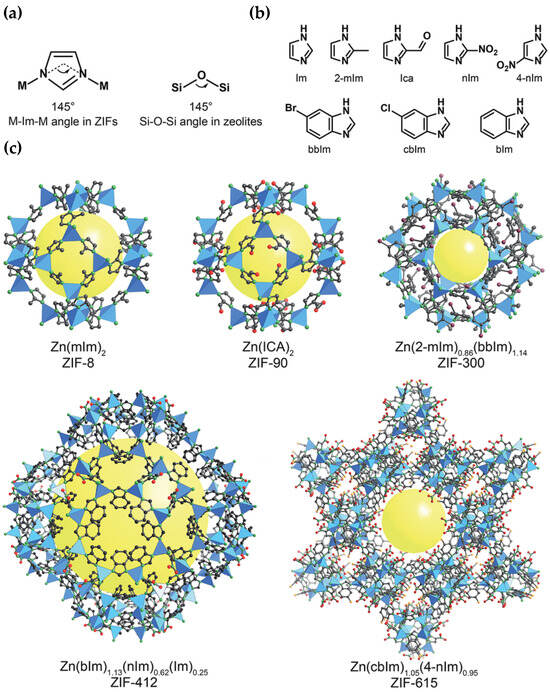
2-philic groups and sites, is zeolitic imidazolate framework-8 (ZIF-8) (
Figure 59). ZIF-8 was incorporated as a filler by Wang et al. (2024)
[42][105] into a Pebax matrix (60 wt % polyethylene oxide and 40 wt % polyamide 6), and the obtained MMM achieved enhanced CO
2 separation performance. Other novel MOF-based membranes, which offer significant benefits, e.g., enhanced separation performance, defect-free structures and improved mechanical properties, include ionic liquid (IL)-MOF membranes, covalent organic framework (COF)-MOF membranes and MOF-glass membranes
[43][106].
Figure 59. Zeolitic imidazolate frameworks (ZIFs): (
a) design of a ZIF using tetrahedral metals and imidazolates to present tetrahedral topologies typically found in zeolites, (
b) main imidazolate linkers which are applied during ZIF synthesis, and (
c) crystal structures of a ZIF with various pore sizes and openings. Atom labelling scheme: C, black; O, red; N, green; Br, purple; Cl, orange; and Zn, blue polyhedra. H atoms are not depicted for clarity. Yellow spheres represent the space in the framework
[44][107].
2.2. Carbon Molecular Sieve (CMS) Membranes
Carbon molecular sieves (CMSs) are a type of activated carbons with pores of a very low (molecule) size, which have been utilized for separating O
2 from air and CO
2 during biogas upgrading. However, they are much less investigated for CO
2/N
2 separation and carbon capture from flue gases
[45][108]. The rigid pore structure of CMS membranes presents a bi-modal pore-size distribution, where the micropores (7–20 Å) improve gas permeability and the ultra-micropores (<7 Å) enhance gas selectivity through molecular sieving. Due to these properties, CMS membranes are often utilized for separating gases with similar molecular kinetic diameters
[46][47][109,110]. CMS membranes have attracted worldwide attention as they exhibit higher chemical and thermal stability and enhanced gas separation performance compared to polymeric membranes. Several polymers are used to synthesize CMS membranes, such as polyimides, phenol formaldehyde, cellulose, poly(phenylene oxide), sol–gel polymers, poly(vinylidene chloride-co-vinyl chloride) and poly(furfuryl alcohol). Among the aforementioned materials, poly(furfuryl alcohol) is considered a strong possible precursor for manufacturing high-performance CMS membranes
[48][49][111,112].
The development of MMMs which contain CMSs has been examined by various researchers. A suitable filler must withstand high temperatures and be easy to prepare, taking into account the preparation conditions of CMS membranes and the demand for economic efficiency
[50][113]. Li et al. (2019)
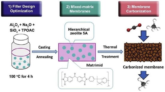
[51][114] adopted the strategy of filler design optimization with membrane carbonization to produce mixed-matrix CMS membranes incorporating a hierarchical zeolite 5A filler (
Figure 610). Apart from its intrinsic micropores, the hierarchical filler also possessed mesopores of ∼8 nm that offered additional transport pathways to facilitate the diffusion of CO
2 through the membrane carbon matrix. More recently, Zhang et al. (2023)
[50][113] incorporated the zeolite ZSM-5 into the carbon matrix of a CMS membrane to fabricate a CMS/ZSM-5 MMM. The results showed that the gas permeabilities of CMS/ZSM-5 MMM for H
2, CO
2, O
2, N
2 and CH
4 were significantly improved in comparison with the pure CMS membranes.
Figure 610. Synthesis procedure of CMS membranes
[51][114].
2.3. Nanocomposite Membranes
When the incorporated inorganic material (filler) is of nano-scale size, the obtained MMMs are also known as nanocomposite membranes. Nanofillers (usually between 1 and 100 nm) are increasingly incorporated in polymeric matrices to produce MMMs in recent years. Nanofillers present molecular sieving ability, an arranged pore structure, good mechanical properties and thermal stability, and their exceptional interfacial compatibility forms special nano-channels for the transportation of CO
2 when they are combined with polymers. Nanofillers in MMMs are used to decrease the gas transport resistance and enlarge the chain spacing in the polymer. In addition, they increase CO
2 solubility in MMMs, while the sieving ability of their porous structure improves significantly the gas selectivity and permeability
[31][95].
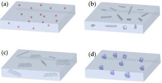
Based on the number of dimensions, nanofillers (and their respective MMMs) can be zero-dimensional (0D), one-dimensional (1D), two-dimensional (2D) and three-dimensional (3D) (
Figure 711). Zero-dimensional nanofillers are typically represented by nanoparticles, which include mainly gold, zinc, silver or metal oxides with a pore size of 1–50 nm usually. One-dimensional nanotubes, nano-wires, nano-rods and nano-fibers are nanomaterials of ‘needle’ shape, while two-dimensional nanomaterials are thin nanosheets with only one external nano-scale dimension. Two-dimensional nanomaterials can reach a few square microns, usually far exceeding their thicknesses. Nanoporous materials, such as zeolites, silicalites and MOFs of polycrystalline structures can be regarded as 3D nanofillers. It must be mentioned that bulk nanoparticles and bundles of 1D materials and multi-nanolayers are also regarded as 3D nanomaterials and, therefore, exhibit tunable properties based on their dispersion state
[52][115].
Figure 711. Mixed-matrix membranes (MMMs) with (
a) 0D nanomaterials (nanoparticles), (
b) 1D nanomaterials (e.g., carbon nanotubes), (
c) 2D nanomaterials (e.g., graphene oxide nanosheets) and (
d) 3D nanomaterials (e.g., microporous nanomaterials)
[52][115].
In recent years, various research studies have investigated the fabrication and utilization of nanocomposite membranes for efficient CO
2 capture. Dai et al. (2023)
[53][116] demonstrated that the addition of one-dimensional carboxymethylcellulose (CMC) between 2D g-C
3N
4 nanosheets is a promising material for CO
2 separation membranes. Using the electrostatic self-assembly method, Zhao et al. (2023)
[38][101] synthesized novel porous amino-functionalized nanosheets with polyethyleneimine (PEI-F-Ce) and combined them with a polyethylene oxide (PEO) matrix to fabricate an MMM (XLPEO/PEI-F-Ce) of high CO
2/N
2 selectivity. It was shown that XLPEO/PEI-F-Ce selectivity was significantly enhanced due to the combined improvement in solubility and reaction selectivity. Maleh et al. (2022)
[54][117] suggested a novel polyethersulfone (PES)-based MMM for separating CO
2 from natural gases and flue gases. These researchers also studied how polyurethane (PU) and clay nano-sheets affect the structure and the separating properties of three MMMs that were based on PES, and showed that the incorporation of PU and clay nano-sheets into the PES matrix significantly improved its gas permeation and separation properties.
2.4. Ionic Liquid (IL)-Based Membranes
Ionic liquids (ILs) are molten organic salts in liquid form, with typical melting points lower than 100 °C
[55][118]. ILs are attracting attention in solvent-based post-combustion CO
2 capture because they present some remarkable characteristics, such as high thermal stability, flammability and low volatility with huge tunability when selecting cations and anions. Due to these properties, high CO
2 solubility and high separation potential for specific gas molecules can be achieved. However, pure ILs present a small surface area and a limited capacity for CO
2 capture
[56][119]. Recently, the combination of ILs with membranes has been reported as a potential separation system. With membrane support, an IL can keep its solvent properties and, consequently, improve its gas separation efficiency. Several distinct types of membrane processes combined with ILs have been investigated, including supported ionic liquid membranes (SILMs), IL composite polymer membranes (ILPMs), IL composite mixed-matrix membranes (ILMMM), poly(ionic liquid) membranes (PILMs), IL gel membranes (ILGMs) and IL membrane contactors (ILMCs). These systems have shown high gas separation efficiency
[57][120].
In recent years, the number of research studies which employ ILs for the fabrication of MMMs with enhanced CO
2 separation characteristics has increased. Mahboubi et al. (2023)
[55][118] combined 1-butyl-3-methylimidazolium acetate, as an ionic liquid, with a polyether-block-amide polymer and aluminium oxide (Al
2O
3) nanoparticles, and prepared a novel ternary MMM with improved permeability and selectivity for CO
2. Nabais et al. (2022)
[58][121] also suggested the incorporation of different azo-porous organic polymers (azo-POPs) (
Figure 812), as fillers, into ion gels with a high IL content (80 wt %) for the fabrication of MMMs with enhanced CO
2 separation characteristics. Ahmad et al. (2018, 2021)
[59][60][122,123] successfully employed an IL as the continuous phase in an MMM and enhanced its CO
2 separation performance. According to Sanni et al. (2022)
[57][120], among the membrane–ionic liquid systems, a hybrid system that is comprised of cellulose acetate, methyl ammonium nitrate and graphene oxide (CA-methyl ammonium nitrate-GO) is a possible candidate with high CO
2 capture (>80%) due to its enhanced porosity, mechanical and thermal stability, good selectivity and low CO
2 permeability.
Figure 812. MMM containing azo-POP in ion gel
[58][121].
2.5. Facilitated Transport Membranes (FTMs)
When CO
2 permeates through a membrane, different transport mechanisms can take place, such as solution diffusion, Knudsen diffusion, convective diffusion, capillary condensation, molecular sieving and facilitated transport. In polymeric membranes, apart from the solution-diffusion mechanism, which is a common gas diffusion mechanism, especially in non-porous polymers, CO
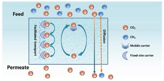
2 transport can be facilitated via reversible chemical reactions between CO
2 and specific molecules (carriers) (
Figure 913)
[61][124]. These membranes, which are known as facilitated transport membranes (FTMs), can reversibly interact with CO
2 and, thus, provide an ‘extra’ mechanism to promote its transport, while other components exclusively pass through the solution-diffusion model
[1][30][60,94]. FTMs have shown great potential for superior gas separation performance and specifically for CO
2 capture
[62][125]. Through the incorporation of carrier agents into the polymer matrices to react with CO
2 reversibly, FTMs provide high flux and selectivity.
Mobile carriers and
fixed carriers are the two predominant FTM types. A mobile carrier is also called a supported liquid membrane (SLM) or an ‘immobilized’ liquid membrane (ILM). This carrier initially reacts with CO
2 on the feed side, and the subsequent product moves across the membrane. On the permeate side, CO
2 is released and H
2 (or other gas species) is not influenced by the facilitated transport. A fixed carrier, which is bonded covalently to the polymer backbone, has limited mobility. Each CO
2 molecule reacts with one carrier site and then passes to the next site until it reaches the permeate side
[31][63][95,126].
Figure 913. Gas transport through a facilitated transport membrane
[61][124].
Researchers have made attempts to establish FTMs in two directions: (i) development of innovative carriers that present high diffusivity and reactivity with CO
2, and (ii) development of low-cost membranes that present very high selectivity. Stability in long-term operation is also necessary as membranes can be exposed to flue gases with NO
x and SO
2 impurities. Until now, only a small number of polymeric membranes have shown to be efficient for CO
2 capture, especially in pilot plants. Polyvinylamine (PVAm), which is a weak linear cationic polyelectrolyte that contains many primary amine groups, is widely reported as appropriate for facilitated CO
2 transportation following various pathways with the presence of water
[33][64][96,127]. Janakiram et al. (2019)
[65][128] used an FTM that consists of a selective layer based on the blend of polyvinyl alcohol (PVA) with sterically hindered PVAm, and achieved 652 GPU of CO
2 permeance, but a rather low CO
2/N
2 selectivity (41.3). In the following years, they scaled up and used three different hollow fiber FTMs with real flue gases from a cement plant
[66][129] and simulated a two-stage membrane process using different classes of facilitated transport membranes, which were previously validated in industrial conditions, with promising results
[67][130]. Wu et al. (2023)
[9][66] also developed SW membrane modules for industrial use with an effective membrane area of 31 m
2. The employed modules consisted of amine-based facilitated transport PVAm multilayer composite membranes, which were fabricated using roll-to-roll coating equipment. The results showed that a reduction in operating pressure increased the purity of CO
2 but decreased the CO
2 capture rate, and there was a trade-off between the power consumption and the membrane area demand. However, although PVAm-based modules have proven to be competitive, compared to most amine-based technologies, the difficulty in maintaining high performance in larger plants still prevents their full-scale application. Aiming to increase the mechanical strength of membranes, the main constituents of polymers coupled with other polymers or nanofillers, carbon nanotubes and metal–organic frameworks (MOFs) are also considered in FTMs
[33][96].
3. Commercially Applied Membrane Modules for Industrial CO2 Capture
Three commercial membrane modules have been successfully demonstrated at a relatively high TRL (5–7) for post-combustion capturing of CO
2 from flue gases of fossil fuel-fired and cement facilities: Polaris
TM, PolyActive
TM and PRISM
TM modules
[68][131].
Polaris
TM, which was developed by Membrane Technology and Research (MTR) (USA), has been broadly examined and assessed for capturing CO
2 from flue gases of coal-fired power plants. Polaris
TM Gen 1, which presents a CO
2 permeance of 1000 GPU and a CO
2/N
2 selectivity of 50, has been tested commercially already
[69][70][71][132,133,134]. During the years 2012–2015, Polaris
TM spiral-wound membranes exhibited prolonged membrane performance (>111,000 h) and achieved >90% CO
2 capture on a bench scale (0.05 MWe or 1 tons of CO
2/day). A larger pilot-scale system (1 MWe or 20 tons of CO
2/day) also presented stable operation (>6 months), achieving 90% CO
2 capture. In this unit, a plate-and-frame module with low-pressure drop, increased packing density and lower power cost (~10 MWe saving) was successfully operated as well. Polaris Gen 2, with twice the CO
2 permeance but similar CO
2/N
2 selectivity, showed higher CO
2 separation performance (60–70%), compared to Gen 1, and also exhibited stable performance for >40 h when it was tested on a laboratory scale. These efforts from MTR have advanced this membrane technology from TRL 2–3 to TRL 6. Aiming to capture 200 tons of CO
2 per day from a coal-fired power plant, a large pilot system is under design with an expected CO
2 purity
> 99%. After the successful operation of such a plant, the commercial maturity of this membrane technology for CO
2 capture is expected to increase to TRL 8. Finally, Polaris
TM membrane performance exhibited high stability (>168 h) during real field tests in 2021 at Jiangyou Power Plant (Jiangyou, China), which operated under dynamic conditions (power plant load ranged between 54 and 84%). The aforementioned results confirm the efficiency of Polaris
TM modules under varying operating conditions
[72][73][32,135].
Helmholtz-Zentrum Geesthacht (Geesthacht, Germany) developed PolyActive
TM module, which showed high CO
2 permeance, namely 3068 m
3 (STP)/m
2/h/bar (1136 GPU), and high CO
2/N
2 selectivity (60), with a CO
2 recovery of 42.7% and a CO
2 purity of 68.2%
[72][74][32,136]. Nowadays, PolyActive™ membranes are broadly applied. Brinkman et al.
[75][137] showed how temperature affects the transport properties of different multilayer PolyActive™ membranes; temperature increased permeance but decreased selectivity. At the optimal temperature (~40 °C), the permeance reached 2000 GPU and the CO
2/N
2 selectivity was almost 45. More information about the mechanical properties of PolyActive™ membranes (structure and thickness) is presented in the work by Schuldt et al.
[76][138]. It was shown that when CO
2 pressure is >8 bar, PolyActive™ swells with CO
2, resulting in lower selectivity
[76][77][13,138].
PRISM™ module, developed by the company Air Products (Allentown, PA, USA), was employed by Scholes et al.
[78][139] at a Victorian brown coal-fired power plant. Initially, the pressure of the flue gas was increased to 150 kPa. The dried flue gas entered the membrane at 45 °C and 3.5 kg/h. After the blower discharge of a direct contact cooler, the module was placed under clean flue gas. However, water condensation on the membrane was the most important drawback of the process. Both selectivity and permeance were greatly reduced after a few hours of operation, which was attributed to membrane plasticization and swelling by water. After some time of operation, they increased slightly, but not up to the initial values. Apart from CO
2, impurities of NO
x and SO
2 also passed through the membrane. Scholes et al.
[78][139] concluded that the main challenge was the fluctuations in humidity and the challenging regulation of the experimental setup in terms of temperature control. Due to humidity, significant changes can happen in membrane transport properties
[77][13].
