Your browser does not fully support modern features. Please upgrade for a smoother experience.
Please note this is a comparison between Version 1 by ling wang and Version 3 by Jessie Wu.
RFID (radio frequency identification) is a self-delivery identification technology that uses radio frequency for non-contact, two-way data exchange. It uses special tags that contain information about the object, which transmit data wirelessly to be read and processed by a reader.
- RFID
- anti-collision algorithm
- ALOHA
- binary tree
1. Introduction
Currently, there are four general categories for tag anti-collision algorithms used in near-field communication: time division multiple access (TDMA), frequency division multiple access (FDMA), code division multiple access (CDMA), and space division multiple access (SDMA) [1]. TDMA is the most efficient and widely used approach to address the RFID tag collision problem because the other three solutions have large hardware implementation requirements, complicated algorithms, and are, thus, rarely used. There are two types of TDMA anti-collision algorithms: one based on the ALOHA mechanism and the other on a tree structure, as shown in Figure 1.
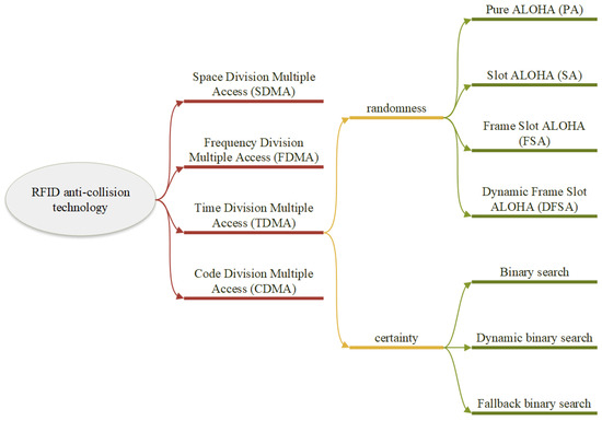
Figure 1.
Classification of tag anti-collision algorithms.
In most cases, the antenna in RFID systems, especially those using TDMA/SDMA/CDMA methods, serves both for transmitting and receiving signals. The separation of these functions, such as transmitting and receiving on different frequencies, can be implemented in methods such as FDMA. Therefore, when discussing algorithms in the TDMA range, it is more appropriate to refer to the reader as a read/write device (RWD) rather than just a reader. This acknowledges the dual functionality of the antenna in RFID systems, as it actively participates in both reading and writing data to the RFID tags.
The classic TDMA-based anti-collision method operates at the protocol level, using protocol control to prevent signal collisions and so accomplish the anti-collision goal. The RFID RWD’s ability to recognize the signal from the tag depends on the communication protocol that is selected between the two devices. Several existing RFID air interface protocols that comply with applicable international standards are analyzed here. It was discovered that the International Organization for Standardization/International Electrotechnical Commission (ISO/IEC) standards and the global Electronic Product Code (EPC) are utilized more frequently than others. The EPC system is a system that includes EAN/UCC coding and is an important part of the EPC, which is characterized by high communication efficiency. ISO and IEC are the main institutions for customizing international standards. Unlike EPCglobal, which focuses on the 860-960 MHz band, ISO/IEC publishes standards for each band, with different standards containing different frequencies and identification algorithms for RFID devices. ISO/IEC 18000-6C is a global communications standard with higher tag recognition throughput than the ISO/IEC 18000-6B standard, while the ISO/IEC 18000-6B and ISO/IEC 18000-6A standards are suitable for refinement.
Table 1 compares the anti-collision algorithms and their performance under different international standards. Among them, ISO/IEC 18000-3 is applicable to the high frequency band 13.56 MHz, and specifies the physical interface, protocol, command, and anti-collision method between the RWD and the tag. Its anti-collision protocol can be divided into two modes. Mode 1 is divided into the basic type and two kinds of extended protocols (no time slot, no termination, multiple electronic tag protocol and time slot, termination, adaptive polling, multiple electronic tag reading protocol). Mode 2 adopts the time–frequency multiplexing FTDMA protocol, with a total of eight channels, which is suitable for situations with a large number of tags.
Table 1.
Table of anti-collision algorithms and their performance under different international standards.
| Applicable Frequency Bands | Anti-Collision Algorithms | International Standard of RFID | Throughput | Complexity |
|---|---|---|---|---|
| HF | QT/PA/FSA | ISO/IEC 18000-3 Mode 1 | Low | Low |
| DBSA | ISO 14443-3A | High | High | |
| SA | ISO/IEC 18000-3 Mode 2 | Low | Low | |
| DFSA | ISO 14443-3B | High | Medium | |
| UHF | TS | ISO/IEC 18000-6B EPCglobal Class 0 EPCglobal Class 1 |
High | High |
| Q/FSA/DFSA | ISO/IEC 18000-6C EPCglobal C1G2 |
High | Medium | |
| BFSA-muting-early-end | ISO/IEC 18000-6A | Medium | High |
ISO/IEC 18000-3 mode 1: basic mode; ISO/IEC 18000-3 mode 2: fast mode.
2. ALOHA-Based Anti-Collision Algorithm
A tag control approach based on the ALOHA algorithm requires that all potential electronic tags be sequentially ordered in the transmit data channel in order to be sent. The quantity of electronic tags determines how quickly this anti-collision device operates; the more tags, the slower the identifying procedure. As a result, this approach is not appropriate in many situations.
- (1)
-
Pure ALOHA algorithm
The pure ALOHA algorithm [2] is the most basic randomness anti-collision algorithm, the basic idea of which is to randomly send information and data to the RWD at some point in time when the tag enters the effective recognition range of the RWD and is activated by the electromagnetic wave signal emitted by the RWD. In the process of the tag sending data, if other tags also send data at the same point in time, it is possible that the data and signals sent by the tag will overlap and a tag collision will occur, thus making it impossible for the colliding tags to be correctly identified by the RWD, as shown in Figure 2.
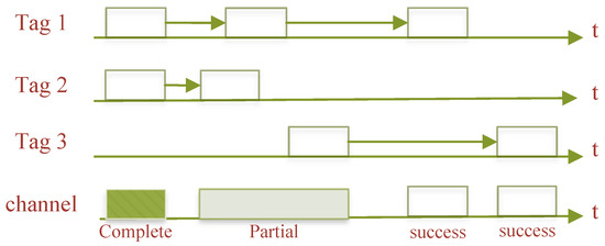
Figure 2.
Pure ALOHA algorithm.
The more serious major issue that can arise with the pure ALOHA algorithm is the logic control unit’s misjudgment, which occurs when a tag repeatedly sends its information after encountering the collision problem and the RWD considers the tag to be outside of its own valid range of action, misjudging the numerical information encoded on the tag. Another issue with this approach is that it has a poor channel usage and low throughput when there are numerous tags present in the same area of operation, since there is a particularly high possibility of collision during the transmission of encoded data from the tag to the RWD.
- (2)
-
Slotted ALOHA algorithm
The slotted ALOHA (SA) algorithm [3][4] is an improvement on the PA algorithm, which divides time of equal length into multiple time intervals, and such time intervals are called slots. The size of each slot is greater than the duration of communication between the RWD and the tag. The tag can only send return data and information to the RWD within a certain slot, and if two or more tags respond to the RWD at the same time, a tag collision occurs within this slot. This is shown in Figure 3.
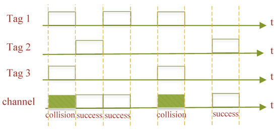
Figure 3.
Slotted ALOHA algorithm.
Any one slot may be in one of the following three states when employing the SA algorithm to solve the system tag collision problem:
-
Successful slot: The RWD can successfully identify the tag supplied within this slot if just one tag transmits back information to the slot.
-
Collision slot: If two or more tags transmit back information to the RWD within the slot, the information from the various tags will conflict and cause a tag collision, making it impossible for the RWD to recognize the tag within this slot.
-
Idle slot: No tag is present in the slot to provide the RWD with return information.
- (3)
-
Framed slotted ALOHA algorithm
The SA algorithm eliminates part of the collision problem by division into slots, but this case of slots leads to successive collisions of tags. The framed slotted ALOHA (FSA) [5] algorithm, which takes into account the limitations of the SA algorithm, further discretizes the time domain by “bundling” a number of slots into a single frame. The tag located within the effective operating range of the RWD antenna randomly chooses a slot in a frame to send an answer signal. Only once in each frame can a tag choose a certain slot to react to. The quantity of tags and the random fallback space are significant variables impacting the algorithm’s performance. The average ratio of effective slots to total slots in each frame is used to indicate the throughput rate of the algorithm, and the higher the effective communication in each frame, the more effective the recognition, as shown in Figure 4.
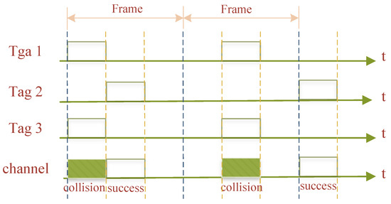
Figure 4.
Framed slotted ALOHA algorithm.
The length of the algorithm frame is determined in advance by the RWD, and the system achieves maximum recognition efficiency when the number of tags sending identification codes is close to the length of the frame slot. The shortcoming of the FSA algorithm is that when the frame length is fixed and the number of tags responding is very large, much larger than the frame length, its throughput rate drops rapidly. If the number of tags returning an answer signal in a given slot is much lower than the number of slots, a large number of slots will be left idle, and the system throughput performance will still be poor. The system throughput rate using the FSA algorithm is low when the number of frame slots differs significantly from the number of tags, which is a significant disadvantage of the FSA algorithm.
- (4)
-
Dynamic Framed Slotted ALOHA algorithm
The Dynamic Framed Slotted ALOHA (DFSA) algorithm [6] is also an improved PA algorithm, which is based on the FSA algorithm, in order to make a certain performance index of the system reach the maximum or minimum value when determining the number of tags dynamically according to the number of tags within the RWD recognition range, or successfully identify slots, collision slots, and idle slots to change the size of the ton, thereby optimizing the RFID system. When the number of collision-prone slots surpasses a predetermined upper limit, for instance, the frame size may be increased, minimizing the likelihood of tag collisions. A reduced frame size can increase the probability of tag collisions when the number of collision-prone slots is below a predetermined lower limit. To recognize all tags in this instance, the RWD does not require a lot of slots. The frame size is automatically expanded when the number of tags is high, which lowers collisions and boosts the system’s slot throughput and recognition efficiency. The number of slots within each frame can be dynamically modified, as seen in Figure 5, to be roughly equal to the number of tags responding to the system.
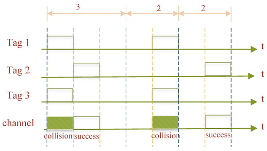
Figure 5.
Dynamic framed slotted ALOHA algorithm.
The ALOHA class randomness tag anti-collision algorithm introduced above is the basic RFID tag anti-collision algorithm. All these algorithms have their own advantages and disadvantages and play a role in practical applications.
3. Anti-Collision Algorithm Based on Tree Structure
When there are many tags to be recognized, the ALOHA-based tag anti-collision method can take a long time to process, increasing the latency of the system. As a result, many RFID applications employ RWD-controlled deterministic tag anti-collision algorithms. Binary tree algorithms, commonly referred to as splitting algorithms, are the major types of deterministic tag anti-collision algorithms. The binary search method is the most popular one for RFID anti-collision issues since it is the easiest to utilize. For the time being, the emphasis lies in enhancing the binary search algorithm’s overall performance and investigating appropriate encoding algorithms to detect conflicting bits.
- (1)
-
Tree splitting algorithm
The randomized tag recognition technique known as the tree splitting (TS) class algorithm is now part of the ISO/IEC 18000-6B UHF RFID standard. The tag has, among other things, a built-in counter with a start value of “0”. A tag with a counter value of “0” provides its ID response in response to an interrogation instruction that is received from the RWD. The RWD will broadcast collision feedback information to the tags within its recognition range if it detects a conflict signal. This causes the response tag to generate a “0” or “1” random number that it will add to its original count value, dividing it into two groups. Tags with a counter value of “1” are simultaneously added to the initial value, increasing it by “1”. The RWD broadcasts a non-collision feedback message, which causes all tag counters to be reduced by “1” from their initial value, if it does not detect a conflict signal. Figure 6, which depicts the TS recognition algorithm in action, demonstrates that it takes nine slots to recognize four tags.
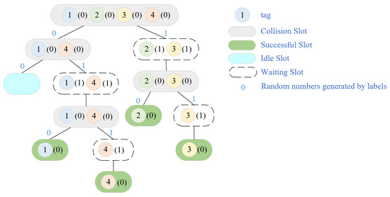
Figure 6.
TS algorithm recognition process.
- (2)
-
Binary search algorithm
The most adaptable and straightforward deterministic technique is the binary search (BS) [7] algorithm, which uses a hierarchical search to pinpoint the precise tag where the collision issue arises. The BS algorithm’s workflow consists of the following, in accordance with its characteristics:
- (1)
-
When a tag enters the RWD’s valid recognition range, the RWD sends a maximum query sequence “Q” to all tags, starting at the same time the transmission of each tag’s individual sequence numbers to the RWD’s reception module.
- (2)
-
The RWD compares the numbers on the same digit of the tag response serial number, and if there is a discrepancy, for example, some tag serial numbers have a “0” in that digit while others have a “1” in that digit, then it can be said that a tag collision has been formed.
- (3)
-
After determining that a tag collision has occurred, the highest collision position of the query sequence “Q” is set to “0”, and the remaining low positions are all set to “1” to obtain a new query sequence “Q”. The number with the largest serial number is excluded one at a time until the RWD compares the number of the serial number of the tag response on the same number of digits is completely consistent, at which point no tag collision has occurred. The number with the least serial number is then chosen at this point.
- (4)
-
The RWD picks the tag pair indicated by the least number of serial numbers, communicates with it, and then puts the tag into a “silent” condition so that it stops responding within the RWD’s recognition range. The tag can reply once more if it is moved both inside and outside of the RWD’s effective recognition range.
- (5)
-
Process (a) is repeated and the tag with the second-to-last serial number is selected for data exchange.
- (6)
-
This process is looped several times until all tags have been successfully identified.
Assume that four tags exist within the radiation range of the RWD antenna, each with the coded sequence numbers 10110010, 10100011, 10110011, and 11100011. Table 2 lists the corresponding binomial tree algorithm implementation process.
Table 2.
Binary search algorithm query process.
| Number of Queries | First Query | Second Query | Third Query |
|---|---|---|---|
| Query sequence | 11111111 | 10111111 | 10101111 |
| Tag A | 10110010 | 10110010 | — |
| Tag B | 10100011 | 10100011 | 10100011 |
| Tag C | 10110011 | 10110011 | — |
| Tag D | 11100011 | — | — |
| Tag Response | 1X1X001X | 101X001X | 10100011 |
| Identification Tags | None | None | Tag B |
The RWD’s query sequence “Q” is too long, and electronic tags must transmit the entire encoding sequence number when the encoding sequence number is too long. This causes redundancy in the BS algorithm, which not only prolongs the algorithm search time but also lowers recognition success rates. Later, researchers introduced the dynamic binary search (DBS) algorithm, an updated technique that has the capacity to dynamically alter the query sequence “Q” and the length of the tag ID throughout the query process, to overcome the redundancy problem of binary search algorithms [8][9]. For each finished query, the BS algorithm will be instructed to start over at the root node, and this algorithm will obviously exhibit redundancy, which not only extends the algorithm’s search time but also results in an unsatisfactory recognition success rate [10]. Many academics have developed various improved BS algorithms, such as the backward binary search algorithm [11], the jumping binary search method [12], the BIBD algorithm [13], etc., for the consideration of these difficulties.
- (3)
-
Query tree algorithm
Given that the BS algorithm cannot use the acquired tag information to enhance the query and that the TS algorithm depends on tags to increase the random number counter, researchers proposed the query tree (QT) algorithm, which is now the most popular deterministic anti-collision algorithm. The RWD command of the QT algorithm has a prefix sequence that is dynamically settable. In response to the RWD, only tags that match the prefix sequence will provide the remaining ID numbers in addition to the prefix sequence. The collision tag will be applied to a new group to be asked again, so the process is repeated until there is only one tag answer. If the RWD detects a conflict signal after this, the “0” and “1” rise in the prefix sequence. Figure 7 depicts the tree structure of the QT method for tag identification. As can be seen, this requires identifying six tags in 13 slots. There are six slots that conflict, one that is empty, and six that are single.
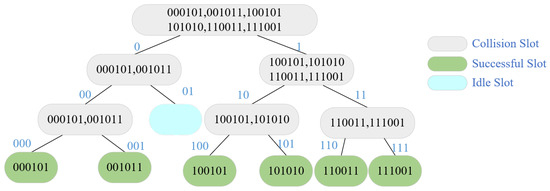
Figure 7.
QT algorithm recognition process.
The length of the tag ID and its ID distribution have an impact on the QT algorithm’s performance. The RWD needs to be given several contradictory cues when several tags share a long common prefix in order to separate the pertinent tags into smaller groups. Researchers have, therefore, suggested a variety of improvements one after another. In conclusion, the tree-structured anti-collision algorithms have low time efficiency and are complex to develop, but can reach large throughput rates.
References
- Abramson, N. Multiple access in wireless digital networks. Proc. IEEE 1994, 82, 1360–1370.
- Hu, J.; Li, Q.; Min, H. Application of time slot ALOHA method in anti-collision problem of RFID system. J. Appl. Sci. 2005, 5, 489–492.
- Vogt, H. Multiple object identification with passive RFID tags. In Proceedings of the IEEE International Conference on Systems, Man and Cybernetics, Yasmine Hammamet, Tunisia, 6–9 October 2002; Volume 3.
- Xia, H.; Tang, M.; Jin, H. A time slot ALOHA-based anti-collision algorithm for RFID systems. Microcomput. Inf. 2008, 17, 239–241.
- Prodanoff, Z.G. Optimal frame size analysis for framed slotted ALOHA based RFID net-works. Comput. Commun. 2010, 33, 648–653.
- Tong, Q.; Zhang, Q.; Min, R.; Zou, X. Bayesian estimation in dynamic framed slotted ALOHA algorithm for RFID system. Comput. Math. Appl. 2012, 64, 1179–1186.
- Xu, L.; Lan, Y. Implementation of RFID binary search method for collision prevention. Appl. Microcontroll. Embed. Syst. 2006, 5, 33–35.
- Massey, J.L. Collision-resolution algorithms and random-access communications. In Multi-User Communication Systems; Springer: New York, NY, USA, 1981; Volume 265, pp. 73–137.
- Sheng, Y.; Du, X. Improved Design and Implementation of Dynamic Binary Search An-ti-collision Algorithm. Comput. Sci. 2012, 39, 135–138.
- Han, X.; Nan, J. RFID anti-collision algorithm based on backward indexed binary tree search. Microelectronics 2013, 5, 708–712.
- An, J.; Wu, J.; Huang, S. Improved RFID binary search anti-collision algorithm. Comput. Eng. Appl. 2009, 45, 229–235.
- Yu, S.; Zhan, Y.; Wang, Z.; Tang, Z. Jumping dynamic tree anti-collision algorithm and its analysis. Comput. Eng. 2005, 09, 19–20+26.
- Li, F.; Cao, D.; Fu, M. Improvement of a BIBD encoded RFID anti-collision algorithm. Comput. Appl. Softw. 2012, 29, 151–154+166.
More