 +1 credit
| Version | Summary | Created by | Modification | Content Size | Created at | Operation |
|---|---|---|---|---|---|---|
| 1 | Feixue Chen | + 4091 word(s) | 4091 | 2021-04-25 05:51:53 | | | |
| 2 | Lily Guo | Meta information modification | 4091 | 2021-04-29 08:47:33 | | |
Video Upload Options
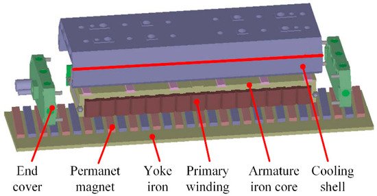
In high-end testing and manufacturing equipment, a trend exists whereby the traditional servo feed system with a ball screw and rotary motor will gradually be replaced by a direct drive system. The precision motion system driven by a permanent magnet linear synchronous motor (PMLSM) offers several advantages, including high speed, high acceleration, and high positioning accuracy. However, the operating precision of the feed device will be affected by the PMLSM robustness to nonlinear and uncertain disturbances, such as cogging force, friction, thermal effects, residual vibration, and load disturbance.
1. Introduction
High-speed and high-precision feed devices, such as detection platforms, machine tools, precision operating systems, and automatic assembly machines, are undergoing rapid development owing to the pressing needs for high productivity and high-precision measurement and manufacturing [1]. Traditional linear motion systems use rotary motors and ball screws to achieve linear motion, but the performance of such a feed drive system is limited by the rotation speed, inertia, backlash, and hysteresis [2]. A feed system driven by a permanent magnet linear synchronous motor (PMLSM), without intermediate mechanical transmission components, offers numerous advantages in dynamic performance and positioning accuracy.
Accordingly, considering the elimination of intermediate transmission structures, PMLSMs also exhibit some difficulties in structure optimization and controller design to achieve the performance of high speed/precision [3][4][5][6]. A PMLSM is a typical nonlinear coupling system, and therefore, the motion accuracy is subject to adverse factors such as thrust force ripple, friction, thermal effects, residual vibrations, and load disturbances. These effects cannot be weakened by an intermediate structure but act on the mover directly. The stability and dynamic characteristics of linear feed devices would be affected, and thus, the operating precision of the system would be degraded.
Thrust ripple and friction are two major nonlinear disturbances acting upon PMLSMs, affecting the dynamic characteristics and inducing vibrations [7][8]. In terms of thrust ripple, it is position-determined and affected by the slot–pole combination. Two main weakening techniques of this ripple are motor structure optimization and force ripple compensation [9]. Friction is a typical disturbance which is dependent on the operating speed. It is necessary to analyze the mechanisms and adjust methods in consideration of the working conditions.
The rapid temperature rise in PMLSMs is usually caused by massive power loss, as a high current density is required for such a direct drive system to achieve large thrust and high speed. The temperature rise in a PMLSM may lead to thermal errors and even demagnetization and winding insulation failure [10][11]. Even with a cooling system, local temperature rise is still inevitable, which will cause parameter variations of the PMLSM and degrade the dynamic performance. Thus, it is essential to investigate the thermal behavior of linear motors and design a controller to compensate for the influence induced by heat.
PMLSMs are characterized by low damping owing to the lack of an intermediate transmission mechanism and, therefore, easily cause transient vibrations [4][12]. With an unsuitable trajectory, the saltation of velocity leads to discontinuities in acceleration and exhibition of infinite jerk [1]. Combined with the requirement of high stiffness, a high regulator coefficient of a controller will make the output of the controller change drastically, thereby causing PMLSM overshoot and residual variation. In order to improve the dynamic performance and positional accuracy, some research studies proposed trajectory planning algorithms, feed-forward and feedback control strategies, and external dampers to improve the PMLSM’s performance.
Load disturbances are directly applied on the mover of a PMLSM and deteriorate the accuracy. Cable force and machine cutting force are common load disturbances in PMLSM motion systems [13]. Generally, load disturbances are difficult to model due to the nonlinear and time-varying characteristics [14]. To suppress load disturbances, in one study, researchers applied a modeless vibration suppression method on a PMLSM motion system [4]. In another method, researchers traced the source and the formation of the load disturbances and then built mathematical models such as a cutting force model, a chatting prediction model, and an electromechanical coupling effect model [15][16][17].
2. Thrust Ripple and Friction
Different from rotary motors, disturbances consisting of thrust ripple and friction decrease the PMLSM system performance directly [18][19] due to the elimination of mechanical transmission [20]. The worst result is that these force ripples excite the mechanical resonances at a special velocity [7]. Therefore, studying the compensation of thrust ripple and friction is vital for PMLSMs. In this section, firstly, the causes of force ripple in PMLSMs are introduced. Then, the motor structure analysis and parameters’ optimization for reducing force ripple are presented. Lastly, the compensation strategies in control systems are compared and discussed.
2.1. Causes of Force Ripple and Friction
The disturbances in PMLSMs are caused by different aspects, including detent force, the harmonics of back-electric motive force (EMF), and driving current.
Compared with that of rotary motors, the end effect force and cogging force of the PMLSM constitute the detent force, and they are the major components of thrust ripple [21]. The detent force is periodic [22] and is only determined by the relative position between the stator and the mover of a motor [23]. It is noted that the force ripple is an electromagnetic effect, which is related to the magnetic field and the phase currents. Moreover, the variations in the magnetic flux density are amplified by the motor magnetic saturation and stator-winding resistance variations [24].
Meanwhile, the current contains harmonic components, which will result in an inaccurate back-EMF model and produce thrust ripple as well [25]. Some structural design methods such as skewing [21][26], segmentation of a magnet [27], and optimization of the magnet pole arc coefficient [28] can effectively suppress the detent force and current harmonics. In terms of system control, approaches such as the dead-time elimination method for a pulse width modulation (PWM)-controlled inverter/converter [29], harmonic injection [30], and adding a resonant controller [31] are proposed to reduce the current harmonics. Simultaneously, friction is velocity-dependent and nonlinear [32], which is non-Lipschitz in the initial state [33]. The disturbances mentioned above will largely degrade the performance of PMLSM systems.
Numerous studies have attempted to compensate for thrust ripple and friction using two methods: structural optimization methods and control compensation strategy [34][35][36].
2.2. Structural Optimization Methods
To date, structural optimization approaches have generally been divided into two types. The first approach is to adjust the size of some critical structures, including modifying the shape of the permanent magnet (PM) [37][38][39][40], installing an auxiliary structure [41], optimizing the length of the stator [34], using fraction slots [36], and adjusting the slot/plot combinations [36], which are promising for reducing detent force.
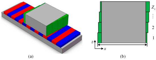
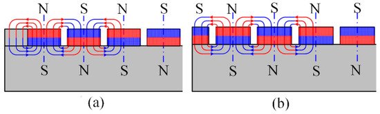
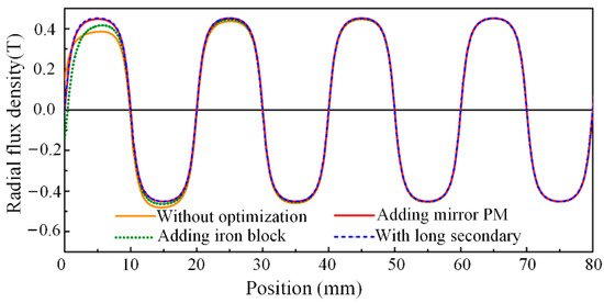
For instance, the detent force caused by the longitudinal end effects in PMLSMs is analyzed and minimized in [41]. First, the left/right-end forces are calculated according to an analytical model. Then, the optimal length of the primary iron is obtained based on the phase difference of the left/right-end forces and a two-step iteration. Furthermore, step-skewed auxiliary irons are added to the primary end to eliminate the second-order harmonics and reduce other high-order harmonics as shown in Figure 1. Finally, some mirror PMs are added to the ends of the secondary back iron as illustrated in Figure 2, and the resultant radial flux density is shown in Figure 3. It can be seen that adding a mirror PM is even more effective in reducing the secondary end effect compared to the results of other methods.
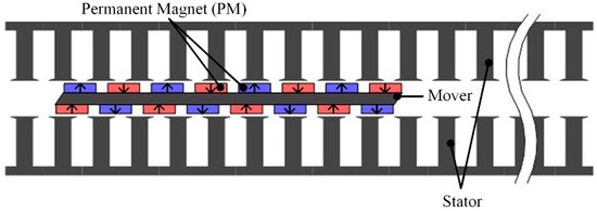
Double-sided designs are popular for minimizing the detent force of PMLSMs [42]. For example, a double-sided long-stator-type PMLSM is presented in [43], as illustrated in Figure 4. The stator is made up of two groups of semi-closed slot iron core, and the concentrated windings are facing each other. The mover side is composed of two groups of permanent magnets mounted on the iron yoke surface. The results show that the structure of the 9-slot/8-pole fractional slot pitch can reduce not only the back-EMF harmonics but also the amplitude of detent force. It was proven that the fractional slot winding structure can effectively suppress the thrust fluctuation of the PMLSM in [36].
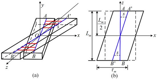
The method of utilizing of step-skewed magnets for thrust ripple reduction is widely used in PMLSM systems [44][45]. As illustrated in Figure 5 [21], skewed PMs with an optimal skewing length are designed to compensate for detent force. The key innovation of the proposed PMLSM is that a skewed structure, as shown in Figure 6, is applied to decrease several high-order harmonics; thus, the sine wave distortion rate of the motor detent force is suppressed. The 2D finite element method (FEM) results show that the fourth-, sixth-, and eight-order harmonics of the optimal skewed PM structure are 55.7%, 93%, and 79.5% lower than those of the rectangular PMs, respectively. In comparison to the traditional structural optimization approaches, the method of reducing the high-frequency components rather than the amplitude of the detent force is more convenient and suitable for the control system to realize the minimal ripple.
Furthermore, the peak-to-peak value of the detent force in PMLSMs is effectively weakened by changing the width of the PM [46][47]. In [48], chamfering also greatly reduced the detent force of PMLSM. All of the methods mentioned above can be classified as designing the key structure of the motor.
The second method is to establish the complete and accurate analytical model first [49]. Then, some optimization algorithms are utilized to obtain the optimal motor parameters for minimizing the thrust ripple and friction [50][51][52][53][54][55].
Concretely, the function of complex relative air gap permeance was introduced by Zarko et al. in [52], and the cogging torque was calculated by integrating the lateral forces that acted on the slot sides. However, this model can only account for the slotting effect; the end detent force that is caused by the longitudinal end effect is neglected.
In [49][50][56], Z. Q. Zhu et al. present the subdomain (SD) method to calculate the air gap field density accurately. It divides the motor model into several regular domains; then, the analytical expression is simplified. Based on Zhu’s method, an accurate analytical model for PMLSMs in 2D Cartesian coordinates was developed in [55]. By adding virtual slots and adopting relative air gap permeance, the end effect and slotting effect are taken into consideration, respectively. Thus, the flux linkage, back-EMF, and detent force are calculated via the proposed method. Both the FEM and prototype results show that the detent force is reduced by the optimization of the end teeth and slots based on the presented model.
Although the abundance of structural optimization designs can attenuate the force ripple effectively, they are frequently accompanied by complicated motor construction and high production costs. Therefore, control methods to decrease the thrust ripple and friction are being researched extensively.
2.3. Compensation Strategy in Control System
Feed-forward control plays a vital part in force ripple compensation [57], and the most common compensation strategy in PMLSM systems is harmonic cancellation by using suitable feed-forward current profiling [58]. As thrust ripple is affected by the magnetic field and phase currents, the phase currents can produce a smooth force only when the back-EMF waveforms are sinusoidal and balanced [59][60][61].
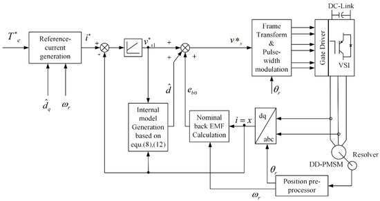
As illustrated in Figure 7, Mohamed proposed a current control approach with a simple adaptive internal model [62], which can estimate the compensation current easily. It is worth mentioning that the proposed model is independent of the current controller, which can be augmented with different kinds of controllers. Evaluations revealed that the presented method could produce very high attenuation at various frequency modes corresponding to the flux harmonics in real time. However, the look-up-table and data-based methods occupy plenty of memory space and sacrifice the compensation accuracy, respectively.
The methods of feed-forward control compensation for thrust ripple in PMLSMs are concretely reported in [63][64][65][66][67]. In [63], a back-EMF compensation method is proposed to obtain a current control scheme independent of the back-EMF variation. In [64], field-oriented control (FOC) is applied, and the components of thrust ripple are extracted by FEM; then, the thrust ripple is compensated by controlling the q-axis current component. In [65], a feed-forward compensator that can generate dither signals is designed to suppress the force ripple.
In [66], the thrust ripple, which is caused by mismatched current waveforms and unbalanced amplifier gain or motor phase, is reduced by optimizing the phase current waveform. The optimized current waveforms are implemented in a motion controller, and the experimental results show that the tracking performance of the PMLSM is significantly improved by using the proposed method.
Moreover, a data-driven variable-gain iterative feed-forward approach is presented in [67] to reduce stochastic disturbance, and the robustness of model uncertainty is improved.
In order to meet the requirements of high stability and strong robustness in parameter variation, the adaptive robust control algorithm is widely implemented in PMLSM systems. Bin Yao et al. conducted substantial digital motion control strategies known as adaptive robust control (ARC) to compensate for major nonlinearities [51][68]. In [51], a discontinuous projection-based ARC controller was designed in particular, and the results indicated that the proposed algorithm exhibits superior tracking performance and avoids the cost of offline identification. However, it tends to compensate for only one or several types of disturbance simultaneously. Then, in [68], an ARC algorithm that offers a complete, simultaneous compensation scheme was used for all major nonlinearities, including coulomb friction, cogging force, and saturating electromagnetic field effect during large driving current. The experimental results show that the proposed approach can achieve an effective overall tracking performance and that it is more suitable for high-precision control.
Furthermore, relay feedback control [2][69], iterative learning control [70], and predictive control [71] can also effectively suppress thrust ripple in PMLSMs, but the key issues are obtaining the specific motion states and compensating for parameters’ variations [72][73][74].
According to the above discussions, thrust force and friction compensation have been extensively studied during recent decades, and it is difficult to eliminate force ripple using a single method. Therefore, further investigations may focus on the combination of both optimal motor designs and optimal control methods.
3. Thermal Effects
Thermal effects have a significant impact on the parameters and performance of PMLSMs. As temperature variations lead to variations in the electrical parameters of PMLSMs and thermal errors, the overall performance, such as dynamic response and precision, will be compromised. Moreover, the maximum temperature increase is the limiting factor of the electric insulation grades in the design phase, and the lifetime of the stator winding has a close relationship with thermal effects. It is necessary to investigate the thermal behavior of linear motors and compensate for the influence induced by thermal effects. This section firstly introduces the heat sources of PMLSMs, and then, different thermal analysis methods are presented and compared. Lastly, thermal compensation methods for linear motor systems are discussed.
3.1. Heat Sources of Linear Motors
As PMLSMs feature high thrust density, high acceleration, and high speed, the main heat sources of PMLSMs include electromagnetic loss (such as copper loss, iron loss, and eddy current loss) and friction [75][76][77]. In general, copper loss is a major part of the total loss, especially in high thrust operation mode with a high current density. Copper loss has a close relationship with the temperature of the windings, as the resistance increases with temperature increase. However, iron loss is the dominant loss in high-frequency operation mode, of which hysteresis loss and eddy current loss are the main components.
Heat source identification is important for the thermal effect management of PMLSMs. Based on the heat source information, more effective measures could be taken to improve the PMLSM performance and working reliability.
3.2. Thermal Analysis of PMLSM
Thermal characteristic models of PMLSMs are essential for predicting temperature distribution. Compared with rotating motors, thermal analysis of PMLSMs is more difficult due to the open structure, large modeling area (at least half of the entire PMLSM), and complex working modes (reciprocating acceleration/deceleration operation, intermittent duty, etc.) [10]. In general, the methods for PMLSM thermal analysis can be summarized as the lumped parameter thermal network (LPTN) and numerical modeling [77][78]. Both methods are proven to be effective to predict the temperature distribution.
The LPTN method uses simplified areas with lumped parameters to represent the complex structures [78]. The LPTN method is characterized by its efficiency, as it relies on an analytical model to determine the temperature distribution. The more detailed the thermal network is, the more accurately it can predict the temperature distribution. When it comes to simple structures, the temperatures predicted using the LPTN method have been found to be in good agreement with numerical simulation results. However, it does take effort to establish accurate models. Further validation and modification through simulation or experimental measurements are needed to make the LPTN method applicable to various motors under different working conditions. Numerical methods, which include finite element analysis (FEA) and computational fluid dynamics (CFD), are strong and valid tools to predict more accurate temperature distributions, even for motors with complex structures. However, they are rather time-consuming and have high computational costs [10][75][78][79][80].
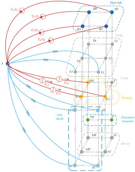
Many publications have reported thermal analyses of PMLSMs using the LPTN method. Tessarolo et al. derived an accurate 3D thermal model of a PMLSM through the LPTN approach, as shown in Figure 8. They proposed computationally efficient techniques that can solve the model analytically based on some simplified hypotheses. The analytical results and experimental measurements have good agreement, which validates the proposed method [81].
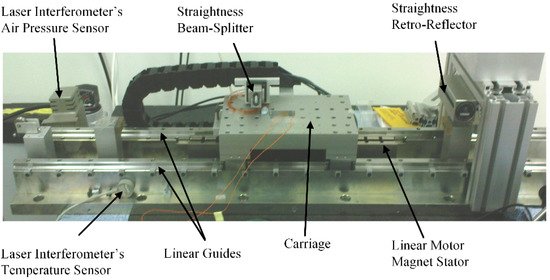
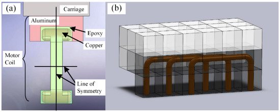
Chow et al. analyzed the thermal deformation of a precision carriage driven by a PMLSM, as shown in Figure 9. They claimed that the joule heat from the motor coils was the main heat source. Furthermore, by comparing the experimental and simulation results, they concluded that thermal boundary conditions were important for accurate estimation of the thermal deformation [82]. Using knowledge of the coil arrangement types, as illustrated in Figure 10, they established a three-dimensional model and adopted the finite difference method to calculate the heat conducted to the carriage [83]. The theoretical calculations were verified with experiments using different current loads. With this method, a temperature prediction model could be obtained with sufficient accuracy.
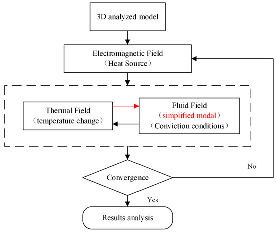
Liu et al. proposed a simplified 3D fluid model to calculate the fluid field of a PMLSM. On the premise of sufficient calculation accuracy, this method reduced the computation time and provided improved practicability. Without considering the inner structure of the mover, the mesh number of the simplified fluid model was significantly reduced, as shown in Figure 11. The thermal simulation results from the electromagnetic-fluid-thermal coupled field are consistent with the experimental results and the error is less than 10%. Moreover, the computation time could be reduced from nearly 110 h to less than 85 h [75].
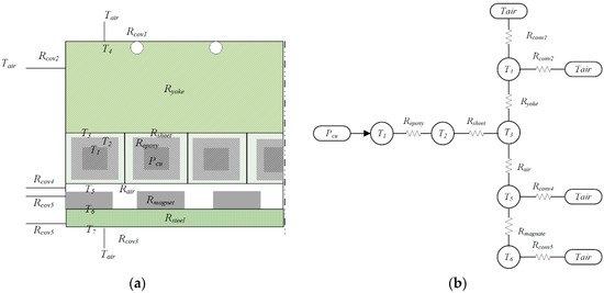
Lu et al. concluded that the temperature increase was a major problem limiting the LM performance. They noted that the thermal analysis of water-cooled PMLSMs was poorly documented. Thus, they investigated the thermal performance of a water-cooled 14-pole and 12-slot PMLSM under continuous duty, short-time duty, and intermittent duty. A one-dimensional thermal resistance network analysis model, as shown in Figure 12, and a two-dimensional FEA model were constructed to obtain the temperature distribution. Thereafter, the impact of the temperature increase on the motor thrust force, efficiency, and power factor was studied through experiments and simulations [10][84]. Furthermore, the water flow rate could be optimized according to the demands [85].
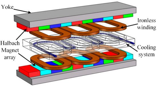
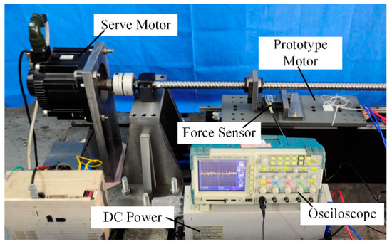
Zhang et al. demonstrated that PMLSMs are suitable for use in ultra-precision positioning, computerized numerical control machine tools, and other processing fields. They proposed an ironless linear synchronous motor with a cooling system, as illustrated in Figure 13. The analytical model of the PMLSM was formulated in 2D Cartesian coordinates. The analytical solution for the flux density in the cooling jacket was established based on the separation of variables method with appropriate boundary conditions. The eddy current braking force induced in the cooling system and the influence of the motor parameters on the eddy current braking force were investigated and validated using the FEM. These authors built a prototype and validated the no-load back-EMF and static thrust by means of experimental results, as shown in Figure 14 [86].
3.3. Controller Design to Compensate
As temperature variations have significant impacts on the parameter accuracy of PMLSMs, such as the winding resistance and the magnetic properties of PMs, controller design with robustness to parameter uncertainty and thermal error modeling are the two main research aspects to compensate for the thermal effects.
Yan et al. addressed the multi-parameter online identification of a long-mover PMLSM based on the extended Kalman filter. The flux linkage and stator resistance were simultaneously identified [87]. Tavallaei et al. designed a robust controller that enables prolonged motion control of a single control input ultrasonic motor (USM) system. The temperature variations significantly affect the dynamic characteristics of the motor and change the resonance frequency of the piezoelectric material. They adopted a Lyapunov function redesign (LFR) robust controller to deal with the uncertainties of the system while ensuring an acceptable performance and stability [88]. Dülk et al. developed a method for estimating the electrical resistance of the coil in a single-coil linear solenoid actuator which is subject to pulse width modulation (PWM) drive conditions [89].
In addition, the PMLSM is one of the heat sources which can cause thermal errors in the direct-driven linear feed systems. In ultra-precision machines, thermal errors have a dominant influence on precision as they are related to more than half of the total errors [90][91]. Many studies focus on thermal error compensation in the linear feed system.
Lin et al. analyzed the influence of thermal dynamic hysteresis on the direct feed axis. Based on one-dimensional heat conduction and thermal expansion theory modeling, an error compensation method of the thermal dynamic characteristic is proposed [92]. Sun et al. optimized the design of important machine parts from the perspective of thermodynamics to improve the thermal performance of an ultra-precision machine tool. They conducted FEM to identify the weak points [93]. Zou et al. presented a thermo-mechanical model to quantify the dynamic error of a high-precision worktable in which both the internal heat sources and environmental thermal fluctuations were considered. The presented model provided a solution for ordinary workshops in environments where the temperature is not controlled to compensate for the thermal errors of the moving units [94]. Lei et al. presented a data-driven modeling method of the thermal error–temperature relationship for the dual-drive ball-screw feed axis. With the low cost and easily accessible unlabeled temperature data under various operation conditions, a co-training semi-supervised support vector machine for the regression method was adopted. The thermal error model was validated through experiments and outperformed the genetic algorithm support vector machines for regression in compensation [95].
In conclusion, the thermal behavior of PMLSMs requires further investigation. For the reduction in heat sources, future work may focus on optimal motor designs considering both the thrust density and efficiency. As the temperature increase is inevitable, forced cooling and insulation techniques are necessary to reduce the impact on the accuracy. The temperature field under certain operation conditions can be predicted using thermal analysis with the LPTN and numerical methods. Moreover, the prediction accuracy can be improved by adopting the improved 3D multi-physical field method with accurate boundary conditions. The simulations should be validated by experiments, including the measurement of the temperature field and thermal deformations. Temperature variations will significantly affect the parameters and dynamic characteristics of the PMLSMs, and robust controllers and thermal error compensation methods for linear motor systems may be combined with the data-driven methods to further mitigate the overall thermal effects.
References
- Yuan, M.; Chen, Z.; Yao, B.; Liu, X. Fast and accurate motion tracking of a linear motor system under kinematic and dynamic constraints: An integrated planning and control approach. IEEE Trans. Control Syst. Technol. 2019.
- Chen, S.L.; Tan, K.K.; Huang, S.; Teo, C.S. Modeling and Compensation of Ripples and Friction in Permanent-Magnet Linear Motor Using a Hysteretic Relay. IEEE/ASME Trans. Mechatron. 2010, 15, 586–594.
- Boduroglu, A.; Gulec, M.; Demir, Y.; Yolacan, E.; Aydin, M. A New Asymmetric Planar V-Shaped Magnet Arrangement for a Linear PM Synchronous Motor. IEEE Trans. Magn. 2019, 55, 1–5.
- Wang, Z.; Hu, C.; Zhu, Y.; He, S.; Yang, K.; Zhang, M. Neural network learning adaptive robust control of an industrial linear motor-driven stage with disturbance rejection ability. IEEE Trans. Ind. Inform. 2017, 13, 2172–2183.
- Chen, Y.-T.; Yu, C.-S.; Chen, P.-N. Feedback Linearization Based Robust Control for Linear Permanent Magnet Synchronous Motors. Energies 2020, 13, 5242.
- Song, J.; Dong, F.; Zhao, J.; Lu, S.; Li, L.; Pan, Z. A new design optimization method for permanent magnet synchronous linear motors. Energies 2016, 9, 992.
- Bascetta, L.; Rocco, P.; Magnani, G. Force Ripple Compensation in Linear Motors Based on Closed-Loop Position-Dependent Identification. IEEE/ASME Trans. Mechatron. 2010, 15, 349–359.
- Wang, Y.; Yu, H.; Che, Z.; Wang, Y.; Zeng, C. Extended state observer-based predictive speed control for permanent magnet linear synchronous motor. Processes 2019, 7, 618.
- Huang, X.Z.; Yu, H.C.; Zhou, B.; Li, L.Y.; Gerada, D.; Gerada, C.; Qian, Z.Y. Detent-Force Minimization of Double-Sided Permanent Magnet Linear Synchronous Motor by Shifting One of the Primary Components. IEEE Trans. Ind. Electron. 2020, 67, 180–191.
- Lu, Q.; Zhang, X.; Chen, Y.; Huang, X.; Ye, Y.; Zhu, Z.Q. Modeling and Investigation of Thermal Characteristics of a Water-Cooled Permanent-Magnet Linear Motor. IEEE Trans. Ind. Appl. 2015, 51, 2086–2096.
- Hao, X.; Peng, B.; Chen, Y.; Xie, G. Transient thermal model of a permanent magnet synchronous planar motor considering spreading thermal resistance. Appl. Therm. Eng. 2015, 81, 1–9.
- Wen, T.; Xiang, B.; Wang, Z.; Zhang, S. Speed control of segmented PMLSM based on improved SMC and speed compensation model. Energies 2020, 13, 981.
- Shao, K.; Zheng, J.; Wang, H.; Xu, F.; Wang, X.; Liang, B. Recursive sliding mode control with adaptive disturbance observer for a linear motor positioner. Mech. Syst. Signal Process. 2021, 146.
- Wu, J.; Pu, D.; Ding, H. Adaptive robust motion control of SISO nonlinear systems with implementation on linear motors. Mechatronics 2007, 17, 263–270.
- Aslan, D.; Altintas, Y. Prediction of Cutting Forces in Five-Axis Milling Using Feed Drive Current Measurements. IEEE/ASME Trans. Mechatron. 2018, 23, 833–844.
- Barrenetxea, D.; Mancisidor, I.; Beudaert, X.; Munoa, J. Increased productivity in centerless grinding using inertial active dampers. Cirp Ann. Manuf. Technol. 2018, 67, 337–340.
- Yang, X.J.; Liu, H.; Lu, D.; Zhao, W.H. Investigation of the dynamic electromechanical coupling due to the thrust harmonics in the linear motor feed system. Mech. Syst. Signal Process. 2018, 111, 492–508.
- Zeng, L.; Chen, X.; Li, X.; Jiang, W.; Luo, X. A Thrust Force Analysis Method for Permanent Magnet Linear Motor Using Schwarz–Christoffel Mapping and Considering Slotting Effect, End Effect, and Magnet Shape. IEEE Trans. Magn. 2015, 51, 1–9.
- Hu, C.; Yao, B.; Wang, Q. Coordinated Adaptive Robust Contouring Control of an Industrial Biaxial Precision Gantry with Cogging Force Compensations. IEEE Trans. Ind. Electron. 2010, 57, 1746–1754.
- Reay, D.S.; Mirkazemi-Moud, M.; Green, T.C.; Williams, B.W. Switched reluctance motor control via fuzzy adaptive systems. IEEE Control Syst. 2002, 15, 8–15.
- Wang, M.; Li, L.; Pan, D. Detent Force Compensation for PMLSM Systems Based on Structural Design and Control Method Combination. IEEE Trans. Ind. Electron. 2015, 62, 6845–6854.
- Boldea, I.; Nasar, S.A. Linear Motion Electromagnetic Devices; Taylor & Francis: Abingdon, UK, 2001.
- Luo, Y.; Chen, Y.; Pi, Y. Cogging effect minimization in PMSM position servo system using dual high-order periodic adaptive learning compensation. ISA Trans. 2010, 49, 479–488.
- Sebastian, T. Temperature effects on torque production and efficiency of PM motors using NdFeB magnets. IEEE Trans. Ind. Appl. 1995, 31, 353–357.
- Sencer, B.; Shamoto, E. Effective Torque Ripple Compensation in Feed Drive Systems Based on the Adaptive Sliding-Mode Controller. IEEE-ASME Trans. Mechatron. 2014, 19, 1764–1772.
- Aydin, M.; Gulec, M. Reduction of Cogging Torque in Double-Rotor Axial-Flux Permanent-Magnet Disk Motors: A Review of Cost-Effective Magnet-Skewing Techniques with Experimental Verification. IEEE Trans. Ind. Electron. 2014, 61, 5025–5034.
- Zhu, Z.Q.; Chen, J.T.; Wu, L.J.; Howe, D. Influence of Stator Asymmetry on Cogging Torque of Permanent Magnet Brushless Machines. IEEE Trans. Magn. 2008, 44, 3851–3854.
- Yamazaki, K.; Fukushima, Y. Effect of Eddy-Current Loss Reduction by Magnet Segmentation in Synchronous Motors with Concentrated Windings. IEEE Trans. Ind. Appl. 2011, 47, 779–788.
- Lin, Y.K.; Lai, Y.S. Dead-Time Elimination of PWM-Controlled Inverter/Converter without Separate Power Sources for Current Polarity Detection Circuit. IEEE Trans. Ind. Electron. 2009, 56, 2121–2127.
- Schoonhoven, G.; Uddin, M.N. Harmonic Injection-Based Adaptive Control of IPMSM Motor Drive for Reduced Motor Current THD. IEEE Trans. Ind. Appl. 2017, 53, 483–491.
- Pan, Z.B.; Dong, F.; Zhao, J.W.; Wang, L.J.; Wang, H.; Feng, Y.Y. Combined Resonant Controller and Two-Degree-of-Freedom PID Controller for PMSLM Current Harmonics Suppression. IEEE Trans. Ind. Electron. 2018, 65, 7558–7568.
- Armstrong-Hélouvry, B.; Dupont, P.; Wit, C.C.D. A survey of models, analysis tools and compensation methods for the control of machines with friction. Automatica 1994, 30, 1083–1138.
- Ahn, H.S.; Chen, Y.Q.; Dou, H. State-periodic adaptive compensation of cogging and Coulomb friction in permanent-magnet linear motors. IEEE Trans. Magn. 2005, 41, 90–98.
- Liu, C.T.; Hwang, C.C.; Li, P.L.; Hung, S.S.; Wendling, P. Design Optimization of a Double-Sided Hybrid Excited Linear Flux Switching PM Motor with Low Force Ripple. IEEE Trans. Magn. 2014, 50, 1–4.
- Ji, J.; Yan, S.; Zhao, W.; Liu, G.; Zhu, X. Minimization of Cogging Force in a Novel Linear Permanent-Magnet Motor for Artificial Hearts. IEEE Trans. Magn. 2013, 49, 3901–3904.
- Lu, Q.; Cheng, C.; Ye, Y.; Fang, Y. Slot/pole number combination research of PM linear motors with fractional slots per pole. Proc. CSEE 2012, 32, 68–74.
- Xia, J.; Shen, L.; Peng, B.; Sun, Y. Influences of cogging effects on normal force ripple in permanent magnet linear servo motors. Zhongguo Dianji Gongcheng Xuebao/Proc. Chin. Soc. Electr. Eng. 2015, 35, 2847–2853.
- Xia, J.; Shen, L.; Peng, B.; Song, D. The magnet-staggered method to weaken the cogging effect normal force ripple of permanent magnet linear servo motor. Trans. China Electrotech. Soc. 2015.
- Xia, J.K.; Li, W.Y.; Shen, L. Skew and End-Teeth Optimization in Reduce Permanent-Magnet Linear Synchronous Motor Normal Force Fluctuation. Adv. Mater. Res. 2012, 383–390, 4853–4859.
- Tavana, N.R.; Shoulaie, A. Pole-shape optimization of permanent-magnet linear synchronous motor for reduction of thrust ripple. Energy Convers. Manag. 2011, 52, 349–354.
- Hu, H.; Liu, X.; Zhao, J.; Guo, Y. Analysis and Minimization of Detent End Force in Linear Permanent Magnet Synchronous Machines. IEEE Trans. Ind. Electron. 2018, 65, 2475–2486.
- Kim, S.-A.; Zhu, Y.-W.; Lee, S.-G.; Saha, S.; Cho, Y.-H. Electromagnetic Normal Force Characteristics of a Permanent Magnet Linear Synchronous Motor with Double Primary Side. IEEE Trans. Magn. 2014, 50.
- Lee, S.-G.; Kim, S.-A.; Saha, S.; Zhu, Y.-W.; Cho, Y.-H. Optimal Structure Design for Minimizing Detent Force of PMLSM for a Ropeless Elevator. IEEE Trans. Magn. 2014, 50.
- Cai, J.-j.; Lu, Q.; Huang, X.; Ye, Y. Thrust Ripple of a Permanent Magnet LSM with Step Skewed Magnets. IEEE Trans. Magn. 2012, 48, 4666–4669.
- Chu, W.Q.; Zhu, Z.Q. Investigation of Torque Ripples in Permanent Magnet Synchronous Machines with Skewing. IEEE Trans. Magn. 2013, 49, 1211–1220.
- Jung, I.S.; Yoon, S.B.; Shim, J.H.; Hyun, D.S. Analysis of forces in a short primary type and a short secondary type permanent magnet linear synchronous motor. IEEE Trans. Energy Convers. 1999, 14, 1265–1270.
- Lim, K.C.; Woo, J.K.; Kang, G.H.; Hong, J.P.; Kim, G.T. Detent force minimization techniques in permanent magnet linear synchronous motors. IEEE Trans. Magn. 2002, 38, 1157–1160.
- Baatar, N.; Yoon, H.S.; Pham, M.T.; Shin, P.S.; Koh, C.S. Shape Optimal Design of a 9-pole 10-slot PMLSM for Detent Force Reduction Using Adaptive Response Surface Method. IEEE Trans. Magn. 2009, 45, 4562–4565.
- Chen, F.; Zhang, C.; Chen, J.; Yang, G. Accurate Subdomain Model for Computing Magnetic Field of Short Moving-Magnet Linear Motor With Halbach Array. IEEE Trans. Magn. 2020, 56, 1–9.
- Zhu, L.; Jiang, S.Z.; Zhu, Z.Q.; Chan, C.C. Analytical Methods for Minimizing Cogging Torque in Permanent-Magnet Machines. IEEE Trans. Magn. 2009, 45, 2023–2031.
- Chen, Z.; Yao, B.; Wang, Q. Accurate Motion Control of Linear Motors with Adaptive Robust Compensation of Nonlinear Electromagnetic Field Effect. IEEE-ASME Trans. Mechatron. 2013, 18, 1122–1129.
- Zarko, D.; Ban, D.; Lipo, T.A. Analytical calculation of magnetic field distribution in the slotted air gap of a surface permanent-magnet motor using complex relative air-gap permeance. IEEE Trans. Magn. 2006, 42, 1828–1837.
- Yeh, S.S.; Su, H.C. Development of friction identification methods for feed drives of CNC machine tools. Int. J. Adv. Manuf. Technol. 2011, 52, 263–278.
- Villegas, F.J.; Hecker, R.L.; Pena, M.E.; Vicente, D.A.; Flores, G.M. Modeling of a linear motor feed drive including pre-rolling friction and aperiodic cogging and ripple. Int. J. Adv. Manuf. Technol. 2014, 73, 267–277.
- Lu, Q.F.; Wu, B.C.; Yao, Y.H.; Shen, Y.M.; Jiang, Q. Analytical Model of Permanent Magnet Linear Synchronous Machines Considering End Effect and Slotting Effect. IEEE Trans. Energy Convers. 2020, 35, 139–148.
- Zhu, Z.Q.; Wu, L.J.; Xia, Z.P. An Accurate Subdomain Model for Magnetic Field Computation in Slotted Surface-Mounted Permanent-Magnet Machines. IEEE Trans. Magn. 2010, 46, 1100–1115.
- Chen, Z.; Kong, W.B.; Zhou, Y.; Qu, R.H.; Fedida, V. Thrust force ripple reduction of H-LVPMM based on dynamic harmonic current compensation. IET Electr. Power Appl. 2020, 14, 226–233.
- Jahns, T.M.; Soong, W.L. Pulsating torque minimization techniques for permanent magnet AC motor drives—A review. IEEE Trans. Ind. Electron. 1996, 43, 321–330.
- Li, X.J.; Wang, Y.G. Sliding-mode control combined with improved adaptive feedforward for wafer scanner. Mech. Syst. Signal Process. 2018, 103, 105–116.
- Wu, J.H.; Liu, C.; Liu, Y.J.; Xiong, Z.H.; Ding, H. Force ripple compensation of the directly-driven linear motors via iterative tuning feed-forward controller. Proc. Inst. Mech. Eng. Part I J. Syst. Control Eng. 2019, 233, 1239–1247.
- Zhang, W.; Nan, N.; Yang, Y.; Zhong, W.; Chen, Y. Force ripple compensation in a PMLSM position servo system using periodic adaptive learning control. ISA Trans 2019, 95, 266–277.
- Mohamed, A.R.I.; El-Saadany, E.F. A Current Control Scheme with an Adaptive Internal Model for Torque Ripple Minimization and Robust Current Regulation in PMSM Drive Systems. IEEE Trans. Energy Convers. 2008, 23, 92–100.
- Dong Seong, O.; Kwan Yuhl, C.; Myong Joong, Y. A discretized current control technique with delayed input voltage feedback for a voltage-fed PWM inverter. IEEE Trans. Power Electron. 1992, 7, 364–373.
- Zhu, Y.-w.; Cho, Y.-H. Thrust ripples suppression of permanent magnet linear synchronous motor. IEEE Trans. Magn. 2007, 43, 2537–2539.
- Tan, K.K.; Lee, T.H.; Dou, H.; Zhao, S. Force ripple suppression in iron-core permanent magnet linear motors using an adaptive dither. J. Frankl. Inst. Eng. Appl. Math. 2004, 341, 375–390.
- Rohrig, C. Current waveform optimization for force ripple compensation of linear synchronous motors. In Proceedings of the 42nd IEEE Conference on Decision and Control, Maui, HI, USA, 9–12 December 2003; pp. 5891–5896.
- Song, F.; Liu, Y.; Jin, W.; Tan, J.; He, W. Data-Driven Feedforward Learning with Force Ripple Compensation for Wafer Stages: A Variable-Gain Robust Approach. IEEE Trans. Neural Netw. Learn. Syst. 2020, 1–15.
- Chen, Z.; Yao, B.; Wang, Q. Adaptive Robust Precision Motion Control of Linear Motors with Integrated Compensation of Nonlinearities and Bearing Flexible Modes. IEEE Trans. Ind. Inform. 2013, 9, 965–973.
- Si-Lu, C.; Kiongtan, K.; Sunan, H. Limit cycles induced in type-1 linear systems with PID-type of relay feedback. Int. J. Syst. Sci. 2009, 40, 1229–1239.
- Butcher, M.; Karimi, A. Linear Parameter-Varying Iterative Learning Control with Application to a Linear Motor System. IEEE-ASME Trans. Mechatron. 2010, 15, 412–420.
- Kim, J.; Cho, K.; Choi, S. Lumped disturbance compensation using extended Kalman filter for permanent magnet linear motor system. Int. J. Control Autom. Syst. 2016, 14, 1–10.
- Feng, B.; Mei, X.; Yang, J.; Enxu, M.U. Adaptive Compensation of Friction Error for Numerical Control Machine Tool. Hsi-Chiao Tung Ta Hsueh/J. Xi’an Jiaotong Univ. 2013, 47, 65–69+96.
- Feng, B.; Mei, X.S.; Yang, J.; Huang, X.Y. Adaptive Configuration Method of Friction Compensation Pulse Characteristic Parameters. J. Shanghai Jiaotong Univ. 2014, 48, 713–718.
- Feng, B.; Zhang, D.; Yang, J.; Guo, S. A Novel Time-Varying Friction Compensation Method for Servomechanism. Math. Probl. Eng. 2015, 1–16.
- Liu, X.; Yu, H.; Shi, Z.; Xia, T.; Hu, M. Electromagnetic-fluid-thermal field calculation and analysis of a permanent magnet linear motor. Appl. Therm. Eng. 2018, 129, 802–811.
- Kim, J.-J.; Jeong, Y.H.; Cho, D.-W. Thermal behavior of a machine tool equipped with linear motors. Int. J. Mach. Tools Manuf. 2004, 44, 749–758.
- Yang, Y.; Bilgin, B.; Kasprzak, M.; Nalakath, S.; Sadek, H.; Preindl, M.; Cotton, J.; Schofield, N.; Emadi, A. Thermal management of electric machines. IET Electr. Syst. Transp. 2017, 7, 104–116.
- Boglietti, A.; Cavagnino, A.; Staton, D.; Shanel, M.; Mueller, M.; Mejuto, C. Evolution and Modern Approaches for Thermal Analysis of Electrical Machines. IEEE Trans. Ind. Electron. 2009, 56, 871–882.
- Aubry, J.; Ahmed, H.B.; Multon, B. Sizing Optimization Methodology of a Surface Permanent Magnet Machine-Converter System over a Torque-Speed Operating Profile: Application to a Wave Energy Converter. IEEE Trans. Ind. Electron. 2012, 59, 2116–2125.
- Huang, X.; Li, L.; Zhou, B.; Zhang, C.; Zhang, Z. Temperature Calculation for Tubular Linear Motor by the Combination of Thermal Circuit and Temperature Field Method Considering the Linear Motion of Air Gap. IEEE Trans. Ind. Electron. 2014, 61, 3923–3931.
- Tessarolo, A.; Bruzzese, C. Computationally Efficient Thermal Analysis of a Low-Speed High-Thrust Linear Electric Actuator with a Three-Dimensional Thermal Network Approach. IEEE Trans. Ind. Electron. 2015, 62, 1410–1420.
- Chow, J.H.; Zhong, Z.W.; Lin, W.; Khoo, L.P. A study of thermal deformation in the carriage of a permanent magnet direct drive linear motor stage. Appl. Therm. Eng. 2012, 48, 89–96.
- Chow, J.; Zhong, Z.; Lin, W.; Khoo, L.; Kiew, C. A finite-difference thermal model of a three-phase coreless linear motor as a heat source. Appl. Therm. Eng. 2015, 87, 605–614.
- Zhang, X.; Lu, Q.; Zhang, Y.; Huang, X.; Ye, Y. Thermal characteristics study of a water-cooled permanent magnet linear motor. In Proceedings of the 2014 Ninth International Conference on Ecological Vehicles and Renewable Energies (EVER), Monte Carlo, Monaco, 25–27 March 2014; pp. 1–9.
- Zhu, Z.Q.; Chen, Y.; Yao, Y.; Lu, Q.; Huang, X.; Ye, Y. Thermal modeling and analysis of double-sided water-cooled permanent magnet linear synchronous machines. COMPEL Int. J. Comput. Math. Electr. Electron. Eng. 2016, 35, 695–712.
- Zhang, L.; Kou, B.; Jin, Y.; Chen, Y.; Liu, Y. Investigation of an Ironless Permanent Magnet Linear Synchronous Motor with Cooling System. Appl. Sci. 2016, 6, 422.
- Yan, L.; Zhang, D.; Bai, Z.; Ye, P.; Zhang, C. Online Multi-parameter Identification of Long-mover Permanent Magnet Linear Motor. In Proceedings of the 2019 22nd International Conference on Electrical Machines and Systems (ICEMS), Harbin, China, 11–14 August 2019; pp. 1–5.
- Tavallaei, M.A.; Atashzar, S.F.; Drangova, M. Robust Motion Control of Ultrasonic Motors under Temperature Disturbance. IEEE Trans. Ind. Electron. 2016, 63, 2360–2368.
- Dülk, I.; Kovácsházy, T. Parameter Estimation in Linear Electromagnetic Devices. IEEE Trans. Ind. Electron. 2015, 62, 3619–3628.
- Ramesh, R.; Mannan, M.A.; Poo, A.N. Error compensation in machine tools—A review: Part II: Thermal errors. Int. J. Mach. Tools Manuf. 2000, 40, 1257–1284.
- Mayr, J.; Jedrzejewski, J.; Uhlmann, E.; Alkan Donmez, M.; Knapp, W.; Härtig, F.; Wendt, K.; Moriwaki, T.; Shore, P.; Schmitt, R.; et al. Thermal issues in machine tools. CIRP Ann. 2012, 61, 771–791.
- Xiankun, L.; Wei, Z.; Zhenhua, F. Thermal Dynamic Hysteresis Modeling and Compensation for Linear Motor Driven Feed Mechanism. J. Mech. Eng. 2018, 54, 137–143.
- Sun, L.; Ren, M.; Hong, H.; Yin, Y. Thermal error reduction based on thermodynamics structure optimization method for an ultra-precision machine tool. Int. J. Adv. Manuf. Technol. 2017, 88, 1267–1277.
- Zou, H.; Wang, B. Thermal effect on the dynamic error of a high-precision worktable. Arch. Civ. Mech. Eng. 2017, 17, 336–343.
- Lei, M.; Yang, J.; Wang, S.; Zhao, L.; Xia, P.; Jiang, G.; Mei, X. Semi-supervised modeling and compensation for the thermal error of precision feed axes. Int. J. Adv. Manuf. Technol. 2019, 104, 4629–4640.

