 +1 credit
| Version | Summary | Created by | Modification | Content Size | Created at | Operation |
|---|---|---|---|---|---|---|
| 1 | Filipa Grifo Cunha | + 2183 word(s) | 2183 | 2021-04-06 08:37:47 | | | |
| 2 | Filipa Grifo Cunha | Meta information modification | 2183 | 2021-04-10 23:00:43 | | | | |
| 3 | Vicky Zhou | Meta information modification | 2183 | 2021-04-12 04:43:53 | | |
Video Upload Options
A critical review is presented of in situ full-field measurements provided by digital image correlation (DIC) for inspecting and enhancing additive manufacturing (AM) processes. The principle of DIC is firstly recalled and its applicability during different AM processes systematically addressed. Relevant customisations of DIC in AM processes are highlighted regarding optical system, lighting and speckled pattern procedures. A perspective is given in view of the impact of in situ monitoring regarding AM processes based on target subjects concerning defect characterisation, evaluation of residual stresses, geometric distortions, strain measurements, numerical modelling validation and material characterisation. Finally, a case study on in situ measurements with DIC for wire and arc additive manufacturing (WAAM) is presented emphasizing opportunities, challenges and solutions.
1. Introduction
Additive manufacturing (AM), also known as 3D printing, is the process of creating a part by joining material, typically by adding news layers over a substrate, in order to obtain a final product from data in a computer-aided design (CAD) model [1]. The AM technology has gained enormous industrial and research interest in recent years, due to its potential for manufacturing complex single-stage components [2]. In the last decade, this technology has come to be seen as a process for manufacturing functional parts for a wide range of polymers and metallic materials. However, as AM typically has a low production rate, it is more suitable for manufacturing specific and complex parts than mass production. It is a technique successfully applied across different areas, from biomedical [3] to electric motors [4] to aerospace industries [5]. Another technological advantage is the ability to produce parts with an almost final shape, thus reducing production time and costs [6]. Nevertheless, products obtained by AM still require further development on open issues regarding internal defects due to printing errors and residual and thermal stresses, for instance [7][8]. This quality uncertainty can create parts wastage, increase parts delivery time and prevent AM implementation in industries that require high performance components with quality assurence.
In the onset of the so-called digital revolution, image-based technologies have been emerging. This progress has allowed the development of full-field optical techniques (FFOTs) for experimental continuum mechanics [9][10]. According to the physical phenomenon involved in the image formation, these methods can be divided into two main categories: white-light (e.g., digital image correlation, grid method, projection moiré) and interferometric (e.g., moiré interferometry, electronic speckle pattern interferometry, speckle shearography) techniques [11][12]. On the one hand, white-light techniques rely on the analysis of the light intensity variation of a geometrical pattern describing the material deformation. These types of techniques can be sorted regarding the characteristic pattern as random, period or feature-based. On the other hand, the interferometric techniques are based on the phenomenon of interference of light waves. These techniques use a monochromatic and coherent light source (e.g., a laser) to illuminate the material surface. Considering the way light interacts with this surface, these methods can be sorted into diffused light (speckle) and diffracted light (grating) interferometric techniques. The selection of a given optical technique is dependent on the application itself. Nevertheless, some guidelines may be defined considering the cost, the simplicity of implementation, the performances (spatial and temporal resolutions, accuracy), the kinematic quantity to be measured (e.g., displacement, strain, curvature), the expected range of deformation and the sensitivity to vibrations and the size of the region of interest (from nano to structural scales). The impact of FFOTs in providing kinematic measurements across a whole region of interest has brought novel insights into different applied scientific areas. Among others, one may underline the measurement of gradient fields [13][14][15], fracture cracking evaluation [16][17][18][19][20], image-based approaches of high-strain rate dynamical behaviour of materials [21][22][23][24][25], numerical modelling validation from image-based measurements [26][27][28] and inverse material parameter identification from heterogeneous tests [29][30][31][32]. Advanced monitoring techniques have also been applied with the AM process in order to enhance the technology.
2. In Situ Monitoring Using Full-Field Measurement Techniques
Several references in the literature can be pointed concerned with the DIC technique and principle[33]. Generically, three different optical configurations can be proposed known as 2D DIC, 3D DIC (stereovision) and digital volume correlation (DVC). A survey on the 2D DIC version can be found in [34], which covers the main principle and methodology to obtain displacement and strain fields from image correlation. Detailed discussions are given concerning measurement accuracy from both experimental conditions and algorithm details. Measures to achieve high accuracy deformation measurements are also recommended. This review was recently updated covering historical achievements, recent advances and open questions for further developments [35]. These articles are rather theoretical and therefore no practical code implementation is given. A recent paper in [36] aimed to overcome this gap, discussing code implementation in a scripting language for 2D DIC. An overview of the principle and applications of the stereovision set-up for experimental mechanics, which employees two cameras to measure 3D displacement and strain fields on any 3D object, is presented in [37]. Finally, a review of DVD can be found in [38], in which achievements, challenges, sources of measurement bias and uncertainties were analysed and ex-situ and in situ experiments discussed. The 2D/3D DIC technique provides full-field, contactless displacements of a target object by correlating images recorded before and after the application of a given deformation. The subset-based correlation method is typically implemented in most available codes, although other approaches have been proposed such as the (global) finite element-based DIC [39] and the Fourier-based DIC [40]. There are several commercial software available in the market including Correlated Solutions [41], GOM Correlate [42], MatchID [43], LaVision [44] and Eikosim [45]. Open-source codes have also been developed such as Ncorr [46], DICe [47], µDIC [48], multiDIC [49], pyxel [50], py2DIC [51], UFreckles [52] and YADICS [53]. In the subset-based approach, the reference (or undeformed) image is typically divided into subsets with may overlap by a step size. These are basic parameters that will influence the spatial resolution and accuracy of the measurements. Therefore, their selection typically requires a convergence study, in a compromise between correlation (small subsets) and interpolation (large subsets) errors [15][54][55]. Several mathematical correlation criteria have been proposed for estimating the displacement field in the subset matching algorithm approach [35].
3. In Situ Monitoring of Additive Manufacturing Using Digital Image Correlation
3.1. Applications
Among the scientific publications addressing in situ measurements using DIC in AM, a systematic review is presented highlighting objectives, methodologies, results and conclusions. The discussion will be outlined according the following research topics:
• Defect characterisation;
• Evaluation of residual stresses;
• Geometric distortions;
• Numerical modelling validation based on in situ measurements;
• Monitoring and part characterisation.
3.2. Customisation of the DIC to AM Process: Challenges
-
Optical and Lighting System;
-
Speckled Pattern;
-
Radiation;
-
Projected Particles;
-
Camera Position;
-
Curved Objects and Out-of-Plane Deformations;
-
Closed Process Chamber;
-
Relative Motion.
4. In Situ Monitoring of WAAM Using DIC: Challenges and Solutions
In this section, a case study is presented on in situ monitoring of theWAAM process using DIC, presenting preliminary results to highlight challenges and solutions. Among all AM process variants,WAAM is one of the most promising [56][57]. WAAM allows a high deposition rate to produce large and complex parts for structural applications. Many different metallic alloys can be used, such as steel, titanium, aluminum, or magnesium. Additionally,WAAM can be implemented at a relatively low cost, using conventional MIG/MAG welding machines, together with an XYZ Cartesian positioning system or a robotic arm.
WAAM involves the deposition of successive layers of molten metal, creating many thermal cycling in the layers below. Consequently, high residual stress can be generated, producing distortions in the parts. Additionally, defects can occur, such as porosities, lack of fusion, or cracks. Therefore, the in situ process monitoring is of primary importance, to detect and fix such issues in time. Several NDT has been studied for inline and offline inspection [58][59][60][61] but other reliable monitoring technologies must be developed or adapted for wider industrial implementation. DIC can be a valuable technology for in situ monitoring ofWAAM, but several adverse process conditions prevent the use of DIC during the production of parts by WAAM. Such adverse conditions include:
i. High-intensity electromagnetic radiation: the open electric arc produces a plasma (5000 to 30,000 °C) that radiates in the infrared, visible and ultraviolet wavelengths. This invalidates the use of basic image acquisition optical set-ups for DIC measurements;
ii. High temperature reached in the inspection surface: the melting pool (>1000 °C) produced duringWAAM heats the metal surface preventing the use of conventional painted speckled patterns;
iii. Sparks and projection of melted metal: near the material deposition zone, an intense projection of incandescent metal particles and fume may exist. This prevents positioning the camera near the target surface and also interferes with image acquisition;
iv. Relative movement between camera and target inspection zone: during the material deposition, the WAAM torch moves along the part being produced, making a continuous shift of the target inspection surface.
These issues are further discussed and illustrated, resulting from an experimental application of DIC during the production of aWAAM steel sample. A general overview and recommendations are presented. The sample was produced using a Metal Active Gas (MAG) welding power source PRO MIG 3200 from KEMPY. The wire feed speed was about 4 m/min, the travel speed was about 350 mm/min and the length of the produced samples was 130 mm, using a 1 mm wire diameter AISI316L stainless steel as a feedstock material. The voltage and the electric current prescribed were 20 V DC and 120 A, respectively. The speckled pattern was painted across the region of interest of the part that was firstly manufactured byWAAM, serving as the base for further layer deposition in a two stage procedure approach, similar to the one reported in [62]. The optical system consisted of a Manta G-1236 Allied Vision CMOS camera wit a Nikon AF Nikkor 28–105 mm f/3.5–4.5 D (IF MACRO) lens. The optical set-up coupled with the WAAM apparatus is shown in Figure 1. The DIC analysis was carried out using the MatchID software [43]. In this study, the following DIC setting parameters were used: subset size of 41 × 41 pixels; subset step of 10 × 10 pixels; ZNSSD correlation criterion; bicubic splines image grey level interpolation; affine shape functions; strain window of 5 × 5 control points; displacement approximation using bilinear (Q4) Lagrange polynomials; Green–Lagrange strain calculation algorithm.
Figure 2 presents the original image of theWAAM acquired for DIC purposes. The effect of the high-intensity radiation near the electric arc can be seen, disturbing the image. Consequently, the correspondent DIC image (Figure 3) is inviable. To avoid this problem, a metallic bulkhead was placed in front of the electric arc to block the radiation and to reduce the projections (Figure 4). This procedure clearly improves the DIC image, as can be seen in Figure 5.
 Figure 1. WAAM and DIC set-ups.
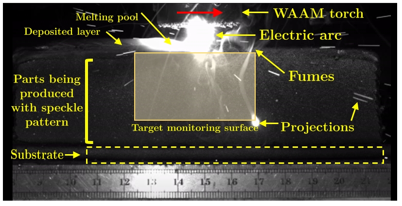
Figure 2. Acquired original image of the WAAM process for DIC purposes.
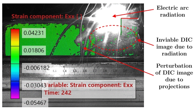
Figure 3. Strain in the horizontal direction calculated from the original image of Figure 1.

Figure 4. Acquired original image of theWAAM process for DIC purposes. In this case, a metallic
bulkhead was used for radiation shield and to reduce the projections.

Figure 5. Principal strain calculated from the original image of Figure 3.
5. Conclusions
The following remarks can be drawn:
-
DIC has been successfully applied for in situ measurements in a few manufacturing processes, namely DED and PBF. The access of full-field measurements has been enhancing the optimisation of AM processes along with the quality of the manufactured part;
-
Research studies using in situ measurements for monitoring AM processes can be grouped in one of the following topics: defect characterisation, evaluation of residual stresses, geometric distortions, numerical modelling validation;
-
The 3D DIC set-up is typically selected to carry out in situ measurements on AM processes. This variant uses two calibrated cameras to register images during the process, which has advantages over the 2D-DIC system, since material deformation can occur generically in the 3D space (e.g., by the occurrence of geometrical distortions generated by residual stresses);
-
LEDs and lasers are the two types of lighting systems used in in situ monitoring. Optical filter in the lenses of the optical system were also used to enhance image quality from the light radiation typically generated in AM processes;
-
The creation of the textured pattern required in in situ DIC measurements was a major issue. On the one hand, a speckled pattern was created by painting using material that is stable at high temperatures. On the other hand, the use of natural textured patterns imaged directly over the surface of the material was explored, with the advantages of not adding an interruptive step to the process. In some AM processes, eventually, an additional material can be added in the procedure to enhance the natural surface. These patterns, however, may not be fully optimised regarding the accuracy associated with the DIC measurements;
-
When applying in situ DIC measurements in AM processes, the following challenges were identified and discussed: optical and lighting system, speckled pattern, radiation, projected particles, camera position, curved objects and out-of-plane deformations, closed process chamber, relative motion;
-
A case study on theWAAM process using a 2D DIC MatchID system was presented. Preliminary results were reported showing the feasibility of in situ DIC measurement in this process. The effect of the high-intensity radiation near the electric arc was discussed and a solution presented using a metallic bulkhead placed in front of the electric arc to block the radiation and to reduce projections.
References
- Frazier, W.E. Metal additive manufacturing: A review. J. Mater. Eng. Perform. 2014, 23, 1917–1928.
- Bartlett, J.L.; Jarama, A.; Jones, J.; Li, X. Prediction of microstructural defects in additive manufacturing from powder bed quality using digital image correlation. Mater. Sci. Eng. A 2020, 794, 140002.
- Mierzejewska, A.A.; Hudák, R.; Sidun, J. Mechanical Properties and Microstructure of DMLS Ti6Al4V Alloy Dedicated to Biomedical Applications. Materials 2019, 12, 176.
- Török, J.; Pollák, M.; Töröková, M.; Murcinková, Z.; Kociško, M. Monitoring of the impacts of used materials for resulting attributes of an electric motor created via additive technology. TEM J. 2020, 9, 826–830.
- Balit, Y. Charkaluk, E.; Constantinescu, A. Digital image correlation for microstructural analysis of deformation pattern in additively manufactured 316L thin walls. Addit. Manuf. 2020, 31, 100862.
- Tofail, S.A.; Koumoulos, E.P.; Bandyopadhyay, A.; Bose, S.; O’Donoghue, L.; Charitidis, C. Additive manufacturing: Scientific and technological challenges, market uptake and opportunities. Mater. Today 2018, 21, 22–37.
- Fang, Z.C.; Wu, Z.L.; Huang, C.G.; Wu, C.W. Review on residual stress in selective laser melting additive manufacturing of alloy parts. Opt. Laser Technol. 2020, 129, 106283.
- Razavykia, A.; Brusa, E.; Delprete, C.; Yavari, R. An Overview of Additive Manufacturing Technologies—A Review to Technical Synthesis in Numerical Study of Selective Laser Melting. Materials 2020, 13, 3895.
- Grédiac, M.; Hild, F. Full-Field Measurements and Identification in Solid Mechanics; John Wiley and Sons: Hoboken, NJ, USA, 2012.
- Rastogi, P.; Hack, E. Optical Methods for Solid Mechanics: A Full-Field Approach; John Wiley and Sons: Hoboken, NJ, USA, 2012; p. 432.
- Cloud, G. Optical Methods of Engineering Analysis; Cambridge University Press: New York, NY, USA, 1995.
- Sciammarella, C.; Sciammarella, F. Experimental Mechanics of Solids; John Wiley and Sons: Hoboken, NJ, USA, 2012; p. 776.
- Lagattu, F.; Brillaud, J.; Lafarie-Frenot, M.C. High strain gradient measurements by using digital image correlation technique. Mater. Charact. 2004, 53, 17–28.
- Dang, D.; Pitti, R.M.; Toussaint, E.; Grédiac, M. Inverse identification of early- and latewood hydric properties using full-field measurements. Wood Mater. Sci. Eng. 2018, 13, 50–63.
- Pereira, J.; Xavier, J.; Ghiassi, B.; Lousada, J.; Morais, J. On the identification of earlywood and latewood radial elastic modulus of Pinus pinaster by digital image correlation: A parametric analysis. J. Strain Anal. Eng. Des. 2018, 53, 566–574.
- Samadian, K.; Hertelé, S.; De Waele, W. Measurement of CTOD along a surface crack by means of digital image correlation. Eng. Fract. Mech. 2019, 205, 470–485.
- Cappello, R.; Pitarresi, G.; Xavier, J.; Catalanotti, G. Experimental determination of mode I fracture parameters in orthotropic materials by means of Digital Image Correlation. Theor. Appl. Fract. Mec. 2020, 108, 102663.
- Majano-Majano, A.; Lara-Bocanegra, A.J.; Xavier, J.; Morais, J. Measuring the Cohesive Law in Mode I Loading of Eucalyptus globulus. Materials 2019, 12, 23.
- Majano-Majano, A.; Lara-Bocanegra, A.J.; Xavier, J.; Morais, J. Experimental Evaluation of Mode II fracture Properties of Eucalyptus globulus L. Materials 2020, 13, 745.
- Oliveira, J.; Xavier, J.; Pereira, F.; Morais, J.; de Moura, M. Direct evaluation of mixed mode I+II cohesive laws of wood by coupling MMB test with DIC. Materials 2021, 14, 374.
- Blitterswyk, J.V.; Fletcher, L.; Pierron, F. Image-Based Inertial Impact Test for Composite Interlaminar Tensile Properties. J. Dyn. Behav. Mater. 2018, 4, 543–572.
- Fletcher, L.; Pierron, F. An Image-Based Inertial Impact (IBII) Test for Tungsten Carbide Cermets. J. Dyn. Behav. Mater. 2018, 4, 481–504.
- Fletcher, L.; Van-Blitterswyk, J.; Pierron, F. A Novel Image-Based Inertial Impact Test (IBII) for the Transverse Properties of Composites at High Strain Rates. J. Dyn. Behav. Mater. 2019, 5, 65–92.
- Kuhn, P.; Catalanotti, G.; Xavier, J.; Ploeckl, M.; Koerber, H. Determination of the crack resistance curve for intralaminar fiber tensile failure mode in polymer composites under high rate loading. Compos. Struct. 2018, 204, 276–287.
- Catalanotti, G.; Kuhn, P.; Xavier, J.; Koerber, H. High strain rate characterisation of intralaminar fracture toughness of GFRPs for longitudinal tension and compression failure. Compos. Struct. 2020, 240, 112068.
- Xavier, J.; Pereira, J.; de Jesus, A. Characterisation of steel components under monotonic loading by means of image-based methods. Opt. Lasers Eng. 2014, 53, 142–151.
- Hack, E.; Lampeas, G.; Patterson, E. An evaluation of a protocol for the validation of computational solid mechanics models. J. Strain Anal. Eng. Des. 2016, 51, 5–13.
- Felipe-Sesé, L.; López-Alba, E.; Hannemann, B.; Schmeer, S.; Diaz, F.A. A Validation Approach for Quasistatic Numerical/Experimental Indentation Analysis in Soft Materials Using 3D Digital Image Correlation. Materials 2017, 10, 722.
- Xavier, J.; Belini, U.; Pierron, F.; Morais, J.; Lousada, J.; Tomazello, M. Characterisation of the bending stiffness components of MDF panels from full-field slope measurements. Wood Sci. Technol. 2013, 47, 423–441.
- Xavier, J.; Pierron, F. Measuring orthotropic bending stiffness components of Pinus Pinaster Virtual Fields Method. J. Strain Anal. Eng. Des. 2018, 53, 556–565.
- Pierron, F.; Grédiac, M. Towards Material Testing 2.0. A review of test design for identification of constitutive parameters from full-field measurements. Strain 2021, 57, e12370.
- Aquino, J.; Andrade-Campos, A.G.; Martins, J.M.P.; Thuillier, S. Design of heterogeneous mechanical tests: Numerical methodology and experimental validation. Strain 2019, 55, e12313.
- Sutton, M.; Orteu, J.J.; Schreier, H.. Image Correlation for Shape, Motion and Deformation Measurements: Basic Concepts, Theory and Applications; Springer: Berlin/Heidelberg, Germany,, 2009; pp. 1.
- Pan, B.; Qian, K.; Xie, H.; Asundi, A. Two-dimensional digital image correlation for in-plane displacement and strain measurement: A review. Meas. Sci. Technol. 2009, 20, 062001.
- Pan, B. Digital image correlation for surface deformation measurement: Historical developments, recent advances and future goals. Meas. Sci. Technol. 2018, 29, 082001.
- Atkinson, D.; Becker, T. A 117 Line 2D Digital Image Correlation Code Written in MATLAB. Remote Sens. 2020, 12, 2906.
- Orteu, J.J. 3-D computer vision in experimental mechanics. Opt. Lasers Eng. 2009, 47, 282–291.
- Buljac, A.; Jailin, C.; Mendoza, A.; Neggers, J.; Taillandier-Thomas, T.; Bouterf, A.; Smaniotto, B.; Hild, F.; Roux, S. Digital Volume Correlation: Review of Progress and Challenges. Exp. Mech. 2018, 58, 661–708.
- Hild, F.; Roux, S. Comparison of Local and Global Approaches to Digital Image Correlation. Exp. Mech. 2012, 52, 1503–1519.
- Su, Y.; Zhang, Q.; Gao, Z.; Xu, X.;Wu, X. Fourier-based interpolation bias prediction in digital image correlation. Opt. Express 2015, 23, 19242–19260.
- Correlated Solutions. 2021. Available online: https://www.correlatedsolutions.com/ (accessed on 4 February 2021).
- GOM ARAMIS/GOM Correlate. 2021. Available online: https://www.gom.com/en/products/3d-testing (accessed on 4 February 2021).
- MatchID. 2021. Available online: https://www.matchid.eu/Software.html (accessed on 4 February 2021).
- The Imetrum. 2021. Available online: https://www.imetrum.com/company/the-imetrum-story/ (accessed on 4 February 2021).
- EikoSim. 2021. Available online: https://eikosim.com/en/use-cases/digital-image-correlation-lattice-structures/ (accessed on 4 February 2021).
- Blaber, J.; Antoniou, B.A.B. Ncorr: Open-Source 2D Digital Image Correlation Matlab Software. Exp. Mech. 2015, 55, 1105–1122.
- Turner, D.; Crozier, P.; Reu, P. Digital Image Correlation Engine (DICe); Sandia National Laboratory: Albuquerque, NM, USA, 2015.
- Olufsen, S.; Andersen, M.; Fagerholt, E. µDIC: An open-source toolkit for digital image correlation. SoftwareX 2020, 11, 100391.
- Solav, D.; Moerman, K.M.; Jaeger, A.M.; Genovese, K.; Herr, H.M. MultiDIC: An Open-Source Toolbox for Multi-View 3D Digital Image Correlation. IEEE Access 2018, 6, 30520–30535.
- Pierré, J.; Passieux, J.; Périé, J. Finite Element Stereo Digital Image Correlation: Framework and Mechanical Regularization. Exp. Mech. 2017, 57, 443–456.
- Belloni, V.; Ravanelli, R.; Nascetti, A.; di Rita, M.; Mattei, D.; Crespi, M. py2DIC: A New Free and Open Source Software for Displacement and Strain Measurements in the Field of Experimental Mechanics. Exp. Mech. 2019, 19, 3832.
- Réthoré, J. 2018 UFreckles. Available online: https://zenodo.org/record/1433776#.YFhTG6_7RPb (accessed on 4 February 2021).
- Seghir, R.;Witz, J.; Coudert, S. YaDICs(2015)—Digital Image Correlation 2/3D. Available online: http://www.yadics.univ-lille1.fr (accessed on 4 February 2021).
- Triconnet, K.; Derrien, K.; Hild, F.; Baptiste, D. Parameter choice for optimized digital image correlation. Opt. Lasers Eng. 2009, 47, 728–737.
- Xavier, J.; de Jesus, A.; Morais, J.; Pinto, J. Stereovision measurements on evaluating the modulus of elasticity of wood by compression tests parallel to the grain. Constr. Bulid. Mater. 2012, 26, 207–215.
- Rodrigues, T.A.; Duarte, V.; Miranda, R.M.; Santos, T.G.; Oliveira, J.P. Current status and perspectives on wire and arc additive manufacturing (WAAM). Materials 2019, 12, 1121.
- Duarte, V.R.; Rodrigues, T.A.; Schell, N.; Miranda, R.M.; Oliveira, J.P.; Santos, T.G. Hot forging wire and arc additive manufacturing (HF-WAAM). Addit. Manuf. 2020, 35, 101193.
- Bento, J.B.; Lopez, A.; Pires, I.; Quintino, L.; Santos, T.G. Non-destructive testing for wire + arc additive manufacturing of aluminium parts. Addit. Manuf. 2019, 29, 100782.
- Lopez, A.B.; Santos, J.; Sousa, J.P.; Santos, T.G.; Quintino, L. Phased Array Ultrasonic Inspection of Metal Additive Manufacturing Parts. J. Nondestruct. Eval. 2019, 38, 1–11.
- Javadi, Y.; MacLeod, C.N.; Pierce, S.G.; Gachagan, A.; Lines, D.; Mineo, C.; Ding, J.;Williams, S.; Vasilev, M.; Mohseni, E.; et al. Ultrasonic phased array inspection of aWire + Arc Additive Manufactured (WAAM) sample with intentionally embedded defects. Addit. Manuf. 2019, 29, 100806.
- Lopez, A.; Bacelar, R.; Pires, I.; Santos, T.G.; Sousa, J.P.; Quintino, L. Non-destructive testing application of radiography and ultrasound for wire and arc additive manufacturing. Addit. Manuf. 2018, 21, 298–306.
- Biegler, M.; Marko, A.; Graf, B.; Rethmeier, M. Finite element analysis of in-situ distortion and bulging for an arbitrarily curved additive manufacturing directed energy deposition geometry. Addit. Manuf. 2018, 24, 264–272.

