 +1 credit
| Version | Summary | Created by | Modification | Content Size | Created at | Operation |
|---|---|---|---|---|---|---|
| 1 | Masahiro Asada | + 3710 word(s) | 3710 | 2021-03-03 05:07:31 | | | |
| 2 | Karina Chen | Meta information modification | 3710 | 2021-04-08 11:25:00 | | |
Video Upload Options
The terahertz (THz) band, which has a frequency of about 0.1 to several THz, is expected to play key roles in various applications, such as imaging, chemical and bio-technological analyses, and communications. Compact solid-state THz sources are important devices for these applications and various kinds of such sources have been studied, comprising both optical and electronic devices, as the THz band is located between millimeter and light waves.
1. Structure, Oscillation Principle, and Oscillation Characteristics of Resonant-Tunneling Diode (RTD) Oscillators
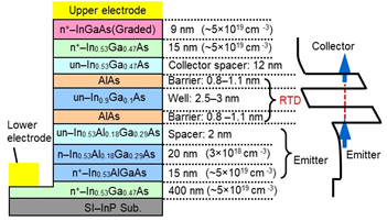
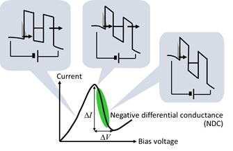
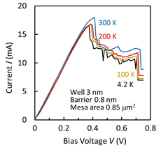
An RTD is made of heterostructures with ultrathin semiconductor multi-layers. The layer structure we use for a THz source is shown in Figure 1a. The main part is composed of an InGaAs quantum well and AlAs double barriers. An InGaAlAs emitter, an InGaAs collector spacer, and a high-doped InGaAs collector are constructed around the main part. These structures are epitaxially grown on a semi-insulating (SI) InP substrate. In DC operations, the conduction band edge of the emitter is lifted by bias voltage, as shown in Figure 1b. At the bias voltage where the conduction band edge of the emitter is aligned to or exceeds the resonance level of the quantum well, the current–voltage (I–V) curve indicates the negative differential conductance (NDC) region, in which the current decreases with increasing bias voltage. This region is used for the THz oscillation. In our RTD structure, a deep quantum well with indium-rich InGaAs and an emitter with InAlGaAs, having a high conduction band edge, are used to reduce the bias voltage required for NDC. Figure 1c shows an example of the measured I–V curves at various temperatures [1]. The NDC region can be seen to have unstable current fluctuation. This fluctuation occurs due to parasitic oscillations in the measurement circuits, composed of leading wires and power supply. The wires and power supply construct a resonance circuit for oscillation, which is described later. Relaxation oscillation [2] and current bi-stability which is caused by charge buildup and depletion in the quantum well [3][4] may also occur in this circuit.
The I–V curves change very little with temperature, probably as the carrier concentration at the conduction band edge of the emitter is insensitive to temperature, due to high Fermi energy, as well as because the AlAs barriers are high. The current density at the peak point is typically 10–30 mA/μm2, while the peak-to-valley current ratio (PVCR) is 2–4. The current density is large for narrow barriers and quantum wells, and strongly depends on the thicknesses of these layers.
(a)
(b)
(c)
Figure 1. Layer structure and current–voltage characteristics of resonant-tunneling diodes (RTDs): (a) Layer structure of InGaAs/AlAs double-barrier RTD. Reprinted with permission from [5]. Copyright (2016) Springer Nature. (b) Schematic I–V curve and potential profile at various bias voltages, and (c) an example of measured I–V curves at various temperatures [1].
As a material combination, we chose InGaAs/AlAs on an InP substrate, as high barriers and high current densities are possible in this system. For high output power, the large voltage width of the NDC region ( in Figure 1b) is desirable, as discussed below. For this purpose, materials with high breakdown voltage may be advantageous. GaN-based material systems may be candidates, although high-frequency operations must be separately investigated. Some results of RTDs with such systems have been reported [6][7][8][9].
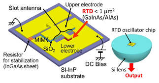
The schematic structure of the fabricated RTD oscillator is shown in Figure 2a [5]. The RTD is placed near the center of one side of a slot antenna, which works as a resonator and a radiator, and the upper electrode of the RTD is connected to the other side of the slot through the capacitance formed by an MIM (metal–insulator–metal) structure. This MIM structure is used to isolate the bias lines to the upper and lower electrodes of the RTD. Outside of the slot antenna and RTD, a resistor for stabilization is connected in parallel with the RTD to suppress parasitic oscillations formed by the circuit, including the leading wires and power supply. By making the reciprocal of this resistor larger than the absolute value of the NDC of the RTD, the NDC is electrically hidden from the outside. As shown in the right-hand side of Figure 2a, the oscillator chip is mounted on a silicon hemispherical or hyper-hemispherical lens, in order to extract the output power, as most of the output is radiated from the slot antenna to the substrate side, due to the large dielectric constant of InP [10]. For a collimated output beam, a hyper-hemispherical lens is used. Structures without silicon lenses have also been reported [11][12][13][14][15].
(a)
(b)
Figure 2. Structure and operating principle of RTD oscillators. Reprinted with permission from [5]. Copyright (2016) Springer Nature: (a) RTD oscillator integrated with slot antenna and entire structure including silicon hemispherical lens, and (b) equivalent circuit, including RTD and slot antenna. Parasitic elements in RTD are neglected for sake of simplicity.
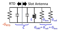
Figure 2b shows the equivalent circuit of the oscillator in the THz frequency region, where is the NDC of the RTD, is the conductance of the slot antenna, which is composed of the radiation conductance and the conductance due to the Ohmic loss , and and are the inductance and capacitance of the RTD and slot antenna. As the capacitance of the RTD is much larger than that of the slot antenna, is dominated by the RTD, while is dominated by the slot antenna. In the device design, and are calculated for the antenna using three-dimensional (3D) electromagnetic simulation and the parallel-plate capacitances of the RTD are calculated for the constituent layers. The additional capacitance caused by the electron delay time is also considered in the RTD [16]. Parasitic elements [5][16] around the RTD are neglected in Figure 2b, for the sake of simplicity in the explanation of oscillation principle.
The condition required for oscillation is at the oscillation frequency . As the oscillation frequency is determined by the total of LC formed by the antenna and RTD, the length of the antenna is usually much shorter than the half-wavelength of the oscillation frequency. For a fixed antenna structure, the oscillation frequency can be increased by reducing the capacitance of the RTD, which is mainly done by reducing the RTD mesa area. However, simultaneously decreases with the reduction of the RTD mesa area. Thus, the oscillation frequency reaches its upper limit () with the reduction of the RTD mesa area. In addition, due to the delay time of electrons in the RTD layers, per area also degrades with increasing frequency.
The above description of the oscillation principle is based on NDC in electrical circuits. As the frequency increases, the photon energy becomes non-negligible and a different explanation, including electron transitions, is needed (as in a laser). However, as the amplification of electromagnetic energy can be expressed by an equivalent circuit, the above electrical description can be used as an approximate one, by changing parameters such as NDC.
Considering the above conditions, the requirements for an RTD to obtain high oscillation frequency are high per area at high frequency and low capacitance per area. Small values of and are also required for the antenna. in cannot be reduced, as the output power is determined by (see below). Although the parasitic elements around the RTD also degrade with increasing frequency, the other effects mentioned above seem to be significant, so far, to increase the oscillation frequency [5][16][17]. At higher frequencies, the effects of the parasitic elements need to be considered in detail.
In order to increase , the current density in the I–V curve is increased with thin barriers and the quantum well, as shown in Figure 1a. The capacitance per unit area is also reduced by inserting the collector spacer layer in Figure 1a. For the electron delay time in RTD layers, the degradation of with frequency is discussed using the approximate formula , where and are the residence time in the double barrier structure and the transit time in the collector spacer layer, respectively [5][16][17]. In the derivation of this formula, is phenomenologically introduced by assuming that electrons are affected only by the time delay at resonant tunneling [16]. A detailed analysis for a more exact treatment is a future subject, including, for example, the potential change due to electron accumulation in the well [18][19], photon-assisted tunneling [20][21][22], and so on, or more precise quantum-mechanical analyses [23][24][25]. In fact, the experimental result of the frequency dependence of [1] slightly deviated from the above formula, although more experimental data are needed.
In any case, it is clear that the delay time must be reduced for higher-frequency oscillation. We used thin barriers and a quantum well to reduce the delay time at resonant tunneling, in addition to high current density [26]. Furthermore, we optimized the thickness of the collector spacer to make and the capacitance as small as possible at the same time. Using these methods, oscillation frequencies up to 1.42 THz have been obtained [27]. The length of the slot antenna was fixed at 20μm, while the oscillation frequency was increased by reducing the RTD mesa area. The RTD mesa area was approximately 0.6 μm2 at 1 THz and 0.2 μm2 at 1.42 THz. The output power was approximately 20 and 1 μW at around 1 and at 1.42 THz respectively, and rapidly decreased as the RTD mesa area approached the upper limit of oscillation.
For the antenna, can be reduced by reducing the conduction loss, which exists on the metal surface around the slot and on the bridge connecting the antenna to the RTD. The former was reduced by optimizing the combination of antenna length and RTD mesa area, through which oscillation up to 1.55 THz has been obtained [28]. The latter was also reduced by improving the structure of the bridge. Through the use of these methods, oscillation up to 1.92 THz has been obtained [29].
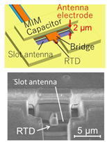
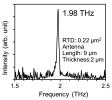
In addition, by making the antenna electrode thicker, the area of the side wall of the slot increases and the conduction loss is further reduced. Combining all of the methods mentioned above, oscillation frequency up to 1.98 THz has been obtained [30], as shown in Figure 3. This is the highest frequency achieved by room-temperature electronic single oscillators, to date.
However, the decrease in saturated with a further increase in thickness of the antenna electrode [31]. This was because the inductance of the slot antenna also decreases with increasing antenna thickness, in addition to the decrease in the resistance of the antenna electrode. As is connected in series with and the relation holds at the angular frequency of oscillation , can be approximately given by . remarkably decreases with increasing antenna thickness, up to approximately 2 μm [31], due to the decrease in and the weak dependence of on antenna thickness. Above this thickness, however, saturates with antenna thickness due to the decrease in . Thus, the upper limit of oscillation frequency saturates with the antenna thickness. Considering this result, a new structure other than the slot-integrated one must be proposed for higher-frequency oscillation, as shown in the next section.
(a)
(b)
Figure 3. RTD oscillator with thick antenna electrode. Copyright (2017) IEEE. Reprinted with permission from [30]: (a) Structure of the oscillator, and (b) oscillation spectra.
The output power of an RTD oscillator is theoretically given by , where is the coefficient of the non-linear term included in the NDC under oscillation [16]. changes with , and is maximized at , i.e., . Using the third-order polynomial approximation of the I–V curve, and can be expressed as [16] and respectively, where and are the current and voltage widths in the NDC region of the I–V curve, as shown in Figure 1b. The maximum output power in the above condition is calculated as . Thus, in order to increase the output power, must be optimized, and must be increased, and must be reduced. The oscillators integrated with slot antennas described above are not optimized for , and their typical output power is a few tens of μW. The of the slot antenna can be designed and optimized through the offset structure, in which the position of the RTD is shifted from the center of the slot and an output power of a few hundred μW has been obtained [32][33]. can be increased by increasing the RTD mesa area; however, the oscillation frequency decreases, due to an increase in capacitance. A structure with a large and small that can maintain the oscillation frequency is shown in the next section. The increase of is a future subject. A possible method may be through the appropriate design of RTD layers (e.g., an increase in thickness of the collector spacer layer), although the upper limit of oscillation frequency must be discussed simultaneously.
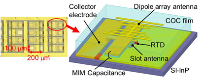
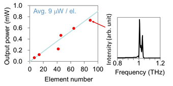
Power combining through array configuration is also useful for obtaining high output power. An oscillator with a two-element array of the offset slot antennas has exhibited an output power of 0.6 mW at 620 GHz [33]. In this array, single-frequency oscillation was observed due to mutual locking between the coupled elements, which implies coherent power combining. In a large-scale array without intentional coupling between the elements, 0.73 mW has been obtained at 1 THz for 89 elements, as shown in Figure 4 [14]. In this device, any intentional coupling structure for stable synchronization was not introduced. However, the elements appeared to be weakly coupled with each other through random reflections and feedback of the output power radiated into the substrate or the dielectric film (COC film in Figure 4). As the elements were not perfectly synchronized, due to weak coupling, multiple peaks were observed in the oscillation spectrum. This behavior is suitable for applications such as imaging in which the interference fringe is a problem in coherent sources.
(a)
(b)
Figure 4. Large-scale array of RTD oscillators. Reprinted from Reference [14] with the permission of AIP Publishing: (a) Structure of the device—an array element is composed of an RTD with a slot antenna (resonator) covered by COC (cyclic olefin copolymer) film and a dipole array antenna (radiator), and (b) output power as a function of element number and oscillation spectrum for 89-element array.
For stable synchronization and coherent power combining, strong coupling between array elements is required; furthermore, as the number of elements increases, stronger coupling is required [34]. As coupling through the circuits on the element plane seems to be limited, another method may be needed, such as putting the entire array into a resonator for strong coupling.
The measurement of the temperature dependence of oscillation characteristics has also been reported [1]. The oscillation frequency was almost constant with temperature, while the output power drastically increased with decreasing temperature between 10 and 300 K. As NDC is insensitive to temperature, as can be seen from Figure 2c, the change in output power was attributed to the change in Ohmic loss of the antenna electrode with temperature. In the narrow temperature range of 300–350 K, the change in the measured output power was small.
2. Applications
Basic research into various applications of RTD oscillators has begun, including for imaging [35], sensors [36], linear encoders [37], communication [38][39][40][41][42], and radars [43][44][45][46], in addition to spectroscopy [47] shown in the previous section. It is a future task to develop various applications of RTD oscillators. Here, we briefly introduce recent applications, especially with respect to communication and radar.
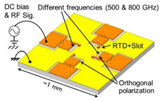
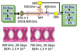
As the output of RTD oscillators can easily be intensity-modulated by direct modulation (i.e., superposition of a signal on the bias voltage), simple high-capacity THz wireless communications are possible. The upper limit of the direct modulation frequency of 30 GHz has been reported [48], which is limited by the capacitance of the external circuit to impose the modulation signal onto the RTD. Simple on-off keying wireless data transmissions have been reported with a data rate of 44 Gbps and an error rate of 5 × 10⁻⁴ below the forward error correction (FEC) limit, and 25 Gbps without error at 650 GHz [38]. Preliminary experiments on transmissions with frequency and polarization multiplexing using RTD oscillators have also been reported [39]. By integrating oscillators having two orthogonal polarizations and two frequencies of 500 and 800 GHz on the same substrate, transmission of 2 × 28 Gbps was obtained, with error below FEC limit in both the frequency and polarization multiplexing. These are also simple on–off keying data transmissions. Figure 5 shows the oscillator chip for frequency and polarization multiplexing, the diagram of the frequency multiplexing, and the transmission result. By improving the external circuit around the RTD for the modulation signal, higher data rates are expected. A transmission experiment using an RTD oscillator with a circularly polarized wave has also been reported [15]. Although the data rate was still low (1 Gbps), it was shown that the error rate was insensitive to oscillator rotation.
Wireless transmission using RTDs as detectors has also been reported [49][42]. The RTD is expected to have a high sensitivity in THz detection, due to the strong non-linearity in the I–V curve, which is the same principle as the detection in SBD (although bias voltage must be applied to use the strong non-linearity in RTD). Other than the detection using such non-linearity, a self-homodyne THz detection mode has recently been reported [42][50]. In this mode, the THz signal is detected by an RTD oscillator which is oscillating near the frequency of the irradiated signal. Through this irradiation, the RTD oscillator is injection-locked and a signal with the homodyne detection is obtained. Through this operation, a low value of NEP (7.7 pW/Hz1/2) has been obtained [50].
(a)
(b)
Figure 5. RTD oscillators with different frequencies and polarizations integrated into one chip for wireless transmission with frequency and polarization multiplexing. Copyright (2017) IEEE. Reprinted with permission from [40]: (a) Schematic structure of the integrated chip, and (b) diagram of the transmission with frequency multiplexing and the resulting eye diagrams—PPG: pulse pattern generator, ED: error detector, BER: bit-error rate, BPF: band-pass filter.
The application of RTD oscillators to THz radar has also been studied [43][44][45][46]. The THz radar has the advantage that it can be used in environments with poor visibility, due to the transparency of THz waves. 3D transparent imaging is also possible by combining THz radar and two-dimensional (2D) imaging systems.
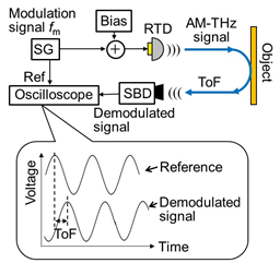
Figure 6 shows a simplified schematic diagram of a system and measurement results of THz radar using an RTD oscillator [43][44]. This system uses the amplitude-modulated continuous wave (AMCW) method. In Figure 6a, the output of the RTD is amplitude-modulated by superimposing a sinusoidal signal on the bias voltage, which is then irradiated onto an object. The reflected wave from the object is received and demodulated by SBD. The time of flight (ToF) of the THz wave from RTD to SBD is determined by the phase difference between the demodulated and reference signals, from which the distance to the object is obtained.
(a)
(b)
Figure 6. THz radar system using RTD oscillator [43, 44]: (a) Simplified schematic diagram of THz radar system using RTD oscillator with the amplitude-modulated continuous wave (AMCW)—SG: signal generator, and (b) error evaluated for the distance measurement with the AMCW using two modulation frequencies.
In this method, when the phase difference between the demodulated and reference signals exceeds 2π, the number of periods included in the phase difference cannot be extracted. To solve this problem, two slightly different frequencies are used for modulation. The phase difference is measured for each frequency, in order to extract the number of the periods included in the phase difference. By utilizing the fact that the period number must be an integer, the error in this number caused by noise is totally removed and high accuracy in the phase evaluation can be obtained.
Furthermore, the oscilloscope in Figure 6a can be replaced with an In-phase/Quadrature (IQ) demodulation system, in order to obtain an accurate phase difference. In the IQ demodulation, the demodulated signal from the SBD is separately mixed with the reference signal and its 90 degree-shifted signal, and two orthogonal components of the mixing output are obtained. The phase difference is calculated from the arctangent of the amplitude ratio of these two components. By introducing the above improvements, distance measurement with an error (standard deviation) of 0.063 mm has been achieved for the carrier frequency of 520 GHz, as shown in Figure 6b [44].
The system described above does not utilize the phase difference of the THz wave itself but, instead, the phase difference of the subcarriers superimposed on the THz wave of the RTD output. The features of THz waves can be used as the carrier. This method is very useful for RTD oscillators in which oscillation characteristics, such as frequency, are easily affected by the external feedback [51].
The subcarrier modulation method can be extended to other radar systems, such as the frequency-modulated continuous wave (FMCW) radar. A subcarrier FMCW radar using an RTD oscillator and a preliminary experiment for the distance measurement of two targets have been reported [45].
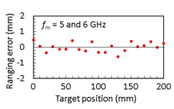
As another extension of subcarrier modulation, a method for measuring the distances of multiple targets has been proposed [46], the principle of which is similar to that of THz optical coherent tomography (OCT) [52]. By changing the modulation frequency (subcarrier frequency) in Figure 6a, the demodulated signal is obtained as a function of . Then, the demodulated signal is decomposed to two orthogonal components by IQ demodulation. For example, for a single target, as shown in Figure 13a, the demodulated signal at the SBD is written as , where is the amplitude of the demodulated signal reflected from the object and is the time delay of the demodulation signal to the reference signal, including propagation times in the space and cables. This signal is decomposed to two components, , where and . and are extracted by the IQ demodulation as a function of . By calculating the inverse Fourier transform of the complex function , the distribution of the target positions can be obtained. For the above single-target case, and the inverse Fourier transform gives , assuming that the dependence of on is weak. Thus, can be extracted and the position of the target found. For multiple targets, a superposition of this form with different values of is obtained, where the distribution of the target position is found. As the bandwidth of is finite in an actual measurement, the result of the inverse Fourier transform for a single target is not a δ-function but a pulse having a finite width approximately given by , where and are the maximum and minimum values of , respectively. This pulse width gives the resolution (in ).
In a preliminary proof-of-concept experiment using this method, the distances of two targets were measured in the range of 20–200 mm, with an error (standard deviation) of approximately 0.6–2.5 mm for and of 3 and 18 GHz, respectively [46]. The error and resolution can be improved by an increase of modulation bandwidth and the use of RTD oscillators with high output power for high signal-to-noise ratio.
References
- Asada, M.; Suzuki, S.; Fukuma, T. Measurements of temperature characteristics and estimation of terahertz negative differential conductance in resonant-tunneling-diode oscillators. AIP Advance 2017, 7, 115226.
- Brown, E.R.; Parker, C.D.; Verghese, S.; Geis, M.W.; Harvey, J.F., Resonant-tunneling transmission-line relaxation oscillator. Appl. Phys. Lett. 1997, 70, 2787–2789.
- Goldman, V.J.; Tsui, D.C.; Cunningham, J.E. Observation of intrinsic bistability in resonant-tunneling structures. Phys. Rev. Lett. 1987, 58, 1256–1259.
- Rasulova, G.K.; Pentin, I.V.; Vakhtomin, Y.B.; Smirnov, K.V.; Khabibullin, R.A.; Klimov, E.A.; Klochkov, A.N.; Goltsman, G.N. Pulsed terahertz radiation from a double-barrier resonant tunneling diode biased into self-oscillation regime. J. Appl. Phys. 2020, 128, 224303.
- Asada, M.; Suzuki, S. Room-temperature oscillation of resonant tunneling diodes close to 2 THz and their functions for various applications. J. Infrared Millim. Terahertz Waves 2016, 37, 1185–1198.
- Kikuchi, A.; Bannai, R.; Kishino, K.; Lee, C.-M.; Chyi, J.-I. AlN/GaN double-barrier resonant tunneling diodes grown by rf-plasma-assisted molecular-beam epitaxy. Appl. Phys. Lett. 2002, 81, 1729–1731.
- Bayram, C.; Vashaei, Z.; Razeghi, M. AlN/GaN double-barrier resonant tunneling diodes grown by metal-organic chemical vapor deposition. Appl. Phys. Lett. 2010, 96, 042103.
- Growden, T.A.; Zhang, W.; Brown, E.R.; Storm, D.F.; Hansen, K.; Fakhimi, P.; Meyer, D.J.; Berger, P.R. 431 kA/cm2 peak tunneling current density in GaN/AlN resonant tunneling diodes. Appl. Phys. Lett. 2018, 112, 033508.
- Encomendero, J.; Yan, R.; Verma, A.; Islam, S.M.; Protasenko, V.; Rouvimov, S.; Fay, P.; Jena, D.; Xing, H.G. Room temperature microwave oscillations in GaN/AlN resonant tunneling diodes with peak current densities up to 220 kA/cm. Appl. Phys. Lett. 2018, 112, 103101.
- Rutledge, D.B.; Neikirk, D.P.; Kasilingam, D.P. Infrared and Millimeter Waves; Button, K.J., Ed.; Academic Press, Orlando FL: 1983; Volume 10, Chapter 1.
- Feiginov, M.; Sydlo, C.; Cojocari, O.; Meissner, P. Resonant-tunnelling-diode oscillators operating at frequencies above 1.1 THz. Appl. Phys. Lett. 2011, 99, 233506.
- Koyama, Y.; Sekiguchi, R.; Ouchi, T. Oscillations up to 1.40 THz from resonant-tunneling-diode-based oscillators with integrated patch antennas. Appl. Phys. Express 2013, 6, 064102.
- Urayama, K.; Aoki, S.; Suzuki, S.; Asada, M.; Sugiyama, H.; Yokoyama, H. Sub-terahertz resonant tunneling diode oscillators integrated with tapered slot antennas for horizontal radiation. Appl. Phys. Express 2009, 2, 044501.
- Kasagi, K.; Suzuki, S.; Asada, M. Large-scale array of resonant-tunneling-diode terahertz oscillator for high output power at 1 THz. J. Appl. Phys. 2019, 125, 151601.
- Horikawa, H.; Chen, Y.; Koike, T.; Suzuki, S.; Asada, M. Resonant-tunneling-diode terahertz oscillator integrated with a radial line slot antenna for circularly polarized wave radiation. Semicond. Sci. Technol. 2018, 33, 114005.
- Asada, M.; Suzuki, S.; Kishimoto, N. Resonant tunneling diodes for sub-terahertz and terahertz oscillators. Jpn. J. Appl. Phys. 2008, 47, 4375–4384.
- Asada, M.; Suzuki, S. Terahertz oscillators using electron devices—An approach with resonant tunneling diodes. IEICE Electron. Express 2011, 8, 1110–1126.
- Feiginov, M.N. Displacement currents and the real part of high-frequency conductance of the resonant tunneling diode. Appl. Phys. Lett. 2001. 78, 3301–3303.
- Feiginov, M. Frequency limitations of resonant-tunnelling diodes in sub-THz and THz oscillators and detectors. J. Infrared Millim. Terahertz Waves 2019, 40, 365–394.
- Liu, H.C. Analytical model of high-frequency resonant tunneling: The first-order ac current response. Phys. Rev. B 1991, 43, 12538–12548; Erratum in 1993, 48, 4877.
- Sugimura, A. Resonant enhancement of terahertz dynamics in double barrier resonant tunneling diodes. Semicond. Sci. Technol. 1994, 9, 512–514.
- Asada, M. Density-matrix modeling of terahertz photon-assisted tunneling and optical gain in resonant tunneling diodes. Jpn. J. Appl. Phys. 2001, 40, 5251–5256.
- Frensley, W. Wigner-function model of a resonant-tunneling semiconductor device. Phys. Rev. B 1987, 36, 1570–1579.
- Kluksdahl, N.C.; Kriman, A.M.; Ferry, D.K. Self-consistent study of the resonant-tunneling diode. Phys. Rev. B 1989, 39, 7720–7735.
- Jonasson, O.; Knezevic, I. Coulomb-driven terahertz-frequency intrinsic current oscillations in a double-barrier tunneling structure. Phys. Rev. B 2014, 90, 165415.
- Kanaya, H.; Shibayama, H.; Sogabe, R.; Suzuki, S.; Asada, M. Fundamental oscillation up to 1.31 THz in resonant tunneling diodes with thin well and barriers. Appl. Phys. Express 2012, 5, 124101.
- Kanaya, H.; Sogabe, R.; Maekawa, T.; Suzuki, S.; Asada, M. Fundamental oscillation up to 1.42 THz in resonant tunneling diodes by optimized collector spacer thickness. J. Infrared Millim. Terahertz Waves 2014, 35, 425–431.
- Maekawa, T.; Kanya, H.; Suzki, S.; Asada, M. Frequency increase in terahertz oscillation of resonant tunnelling diode up to 1.55 THz by reduced slot-antenna length. Electron. Lett. 2014, 50, 1214–1216.
- Maekawa, T.; Kanaya, H.; Suzuki, S.; Asada, M. Oscillation up to 1.92 THz in resonant tunneling diode by reduced conduction loss. Appl. Phys. Express 2016, 9, 024101.
- Izumi, R.; Suzuki, S.; Asada, M. 1.98 THz resonant-tunneling-diode oscillator with reduced conduction loss by thick antenna electrode. In Proceedings of the International Conference on Infrared, Millimeter, and Terahertz Waves, Cancun, Mexico, 27 August–1 September 2017; Abstract No. MA3.1.
- Izumi, R.; Sato, T.; Suzuki, S.; Asada, M. Resonant-tunneling-diode terahertz oscillator with a cylindrical cavity for high-frequency oscillation. AIP Adv. 2019, 9, 085020.
- Shiraishi, M.; Shibayama, H.; Ishigaki, K.; Suzuki, S.; Asada, M.; Sugiyama, H.; Yokoyama, H. High output power (~400 μW) oscillators at around 550 GHz using resonant tunneling diodes with graded emitters and thin barriers. Appl. Phys. Express 2011, 4, 064101.
- Suzuki, S.; Shiraishi, M.; Shibayama, H.; Asada, M. High-power operation of terahertz oscillators with resonant tunneling diode using impedance-matched antennas and array configuration. IEEE J. Sel. Top. Quantum Electron 2013, 19, 8500108.
- Asada, M.; Suzuki, S. Theoretical analysis of coupled oscillator array using resonant tunneling diodes in subterahertz and terahertz range. J. Appl. Phys. 2008, 103, 124514.
- Miyamoto, T.; Yamaguchi, A.; Mukai, T. Terahertz imaging system with resonant tunneling diodes. Jpn. J. Appl. Phys. 2016, 55, 032201.
- Okamoto, K.; Tsuruda, K.; Diebold, S.; Hisatake, S.; Fujita, M.; Nagatsuma, T. Terahertz sensor using photonic crystal cavity and resonant tunneling diodes. J. Infrared Millim. Terahertz Waves 2017, 38, 1085–1097.
- Yamashita, G.; Tsujita, W.; Tsutada, H.; Ma, R.; Wang, P.; Orlik, P.V.; Suzuki, S.; Dobroiu, A.; Asada, M. Terahertz polarimetric Sensing for linear encoder based on resonant-tunneling-diode and CFRP polarizing. In Proceedings of the International Conference on Infrared, Millimeter, and Terahertz Waves, Paris, France, 1–6 September 2019; Abstract No. 4429649.
- Asada, M.; Suzuki, S. THz oscillators using resonant tunneling diodes and their functions for various applications. In Proceedings of the Workshop in European Microwave Week, Nuremberg, Germany, 8– 13 October 2017; Abstract No. WTu-01.
- Oshima, N.; Hashimoto, K.; Suzuki, S.; Asada, M. Terahertz wireless data transmission with frequency and polarization division multiplexing using resonant-tunneling-diode oscillators. IEEE Trans. Terahertz Sci. Technol. 2017, 7, 593–598.
- Wasige, E. Over 10 Gbps mm-wave and THz wireless links. In Proceedings of the Workshop in European Microwave Week, Madrid, Spain, 25–27 September 2018; Abstract No. WTh04-03.
- Diebold, S.; Nishio, K.; Nishida, Y.; Kim, J.; Tsuruda, K.; Mukai, T.; Fujita, M.; Nagatsuma, T. High-speed error-free wireless data transmission using a terahertz resonant tunneling diode transmitter and receiver. Electron. Lett. 2016, 52, 1999–2001.
- Nishida, Y.; Nishigami, N.; Diebold, S.; Kim, J.; Fujita, M.; Nagatsuma, T. Terahertz coherent receiver using a single resonant tunneling diode. Sci. Rep. 2019, 9, 18125.
- Dobroiu, A.; Wakasugi, R.; Shirakawa, Y.; Suzuki, S.; Asada, M. Absolute and precise terahertz-wave radar based on an amplitude-modulated resonant-tunneling-diode oscillator. Photonics 2018, 5, 52.
- Dobroiu, A.; Wakasugi, R.; Shirakawa, R.; Suzuki, S.; Asada, M. Amplitude-modulated continuous-wave radar in the terahertz range using lock-in phase measurement. Meas. Sci. Technol. 2020, 31, 105001.
- Dobroiu, A.; Shirakawa, Y.; Suzuki, S.; Asada, M.; Ito, H. Subcarrier frequency-modulated continuous-wave radar in the terahertz range based on a resonant-tunneling-diode oscillator. Sensors 2020, 20, 6848.
- Konno, H.; Dobroiu, A.; Suzuki, S.; Asada, M.; Ito, H. OCT technique for distance measurement using an RTD terahertz oscillator. In Proceedings of the International Conference on Infrared, Millimeter, and Terahertz Waves, Buffalo, NY, USA, 8–13 November 2020.
- Kitagawa, S.; Mizuno, M.; Saito, S.; Ogino, K.; Suzuki, S.; Asada, M. Frequency-tunable resonant-tunneling-diode oscillators applied to absorbance measurement. Jpn. J. Appl. Phys. 2017, 56, 058002.
- Ikeda, Y.; Kitagawa, S.; Okada, K.; Suzuki, S.; Asada, M. Direct intensity modulation of resonant-tunneling-diode terahertz oscillator up to ~30GHz. IEICE Electron. Express 2015, 12, 2014116.
- Shiode, T.; Mukai, T.; Kawamura, M.; Nagatsuma, T. Giga-bit wireless communication at 300 GHz using resonant tunneling diode detector. In Proceedings of the Asia Pacific Microwave Conference, Melbourne, Australia, 5–8 December 2011; pp. 1122–1125.
- Takida, Y.; Suzuki, S.; Asada, M.; Minamide, H. Sensitive terahertz-wave detector response originated by negative differential conductance of resonant-tunneling-diode oscillator. Appl. Phys. Lett. 2020, 117, 021107.
- Asada, M.; Suzuki, S. Theoretical analysis of external feedback effect on oscillation characteristics of resonant-tunneling-diode terahertz oscillators. Jpn. J. Appl. Phys. 2015, 54, 070309.
- Nagatsuma, T.; Nishii, H.; Ikeo, T. Terahertz imaging based on optical coherent tomography. Photon. Res. 2014, 2, B64–B69.
- Brown, E.R.; Parker, C.D.; Verghese, S.; Geis, M.W.; Harvey, J.F., Resonant-tunneling transmission-line relaxation oscillator. Appl. Phys. Lett. 1997, 70, 2787–2789.
- Goldman, V.J.; Tsui, D.C.; Cunningham, J.E. Observation of intrinsic bistability in resonant-tunneling structures. Phys. Rev. Lett. 1987, 58, 1256–1259.
- Rasulova, G.K.; Pentin, I.V.; Vakhtomin, Y.B.; Smirnov, K.V.; Khabibullin, R.A.; Klimov, E.A.; Klochkov, A.N.; Goltsman, G.N. Pulsed terahertz radiation from a double-barrier resonant tunneling diode biased into self-oscillation regime. J. Appl. Phys. 2020, 128, 224303.
- Asada, M.; Suzuki, S. Room-temperature oscillation of resonant tunneling diodes close to 2 THz and their functions for various applications. J. Infrared Millim. Terahertz Waves 2016, 37, 1185–1198.
- Kikuchi, A.; Bannai, R.; Kishino, K.; Lee, C.-M.; Chyi, J.-I. AlN/GaN double-barrier resonant tunneling diodes grown by rf-plasma-assisted molecular-beam epitaxy. Appl. Phys. Lett. 2002, 81, 1729–1731.
- Bayram, C.; Vashaei, Z.; Razeghi, M. AlN/GaN double-barrier resonant tunneling diodes grown by metal-organic chemical vapor deposition. Appl. Phys. Lett. 2010, 96, 042103.
- Growden, T.A.; Zhang, W.; Brown, E.R.; Storm, D.F.; Hansen, K.; Fakhimi, P.; Meyer, D.J.; Berger, P.R. 431 kA/cm2 peak tunneling current density in GaN/AlN resonant tunneling diodes. Appl. Phys. Lett. 2018, 112, 033508.
- Encomendero, J.; Yan, R.; Verma, A.; Islam, S.M.; Protasenko, V.; Rouvimov, S.; Fay, P.; Jena, D.; Xing, H.G. Room temperature microwave oscillations in GaN/AlN resonant tunneling diodes with peak current densities up to 220 kA/cm. Appl. Phys. Lett. 2018, 112, 103101.
- Rutledge, D.B.; Neikirk, D.P.; Kasilingam, D.P. Infrared and Millimeter Waves; Button, K.J., Ed.; Academic Press, Orlando FL: 1983; Volume 10, Chapter 1.
- Urayama, K.; Aoki, S.; Suzuki, S.; Asada, M.; Sugiyama, H.; Yokoyama, H. Sub-terahertz resonant tunneling diode oscillators integrated with tapered slot antennas for horizontal radiation. Appl. Phys. Express 2009, 2, 044501.
- Kasagi, K.; Suzuki, S.; Asada, M. Large-scale array of resonant-tunneling-diode terahertz oscillator for high output power at 1 THz. J. Appl. Phys. 2019, 125, 151601.
- Horikawa, H.; Chen, Y.; Koike, T.; Suzuki, S.; Asada, M. Resonant-tunneling-diode terahertz oscillator integrated with a radial line slot antenna for circularly polarized wave radiation. Semicond. Sci. Technol. 2018, 33, 114005.
- Asada, M.; Suzuki, S.; Kishimoto, N. Resonant tunneling diodes for sub-terahertz and terahertz oscillators. Jpn. J. Appl. Phys. 2008, 47, 4375–4384.
- Asada, M.; Suzuki, S. Terahertz oscillators using electron devices—An approach with resonant tunneling diodes. IEICE Electron. Express 2011, 8, 1110–1126.
- Feiginov, M.N. Displacement currents and the real part of high-frequency conductance of the resonant tunneling diode. Appl. Phys. Lett. 2001. 78, 3301–3303.
- Feiginov, M. Frequency limitations of resonant-tunnelling diodes in sub-THz and THz oscillators and detectors. J. Infrared Millim. Terahertz Waves 2019, 40, 365–394.
- Liu, H.C. Analytical model of high-frequency resonant tunneling: The first-order ac current response. Phys. Rev. B 1991, 43, 12538–12548; Erratum in 1993, 48, 4877.
- Sugimura, A. Resonant enhancement of terahertz dynamics in double barrier resonant tunneling diodes. Semicond. Sci. Technol. 1994, 9, 512–514.
- Asada, M. Density-matrix modeling of terahertz photon-assisted tunneling and optical gain in resonant tunneling diodes. Jpn. J. Appl. Phys. 2001, 40, 5251–5256.
- Frensley, W. Wigner-function model of a resonant-tunneling semiconductor device. Phys. Rev. B 1987, 36, 1570–1579.
- Kluksdahl, N.C.; Kriman, A.M.; Ferry, D.K. Self-consistent study of the resonant-tunneling diode. Phys. Rev. B 1989, 39, 7720–7735.
- Jonasson, O.; Knezevic, I. Coulomb-driven terahertz-frequency intrinsic current oscillations in a double-barrier tunneling structure. Phys. Rev. B 2014, 90, 165415.
- Kanaya, H.; Shibayama, H.; Sogabe, R.; Suzuki, S.; Asada, M. Fundamental oscillation up to 1.31 THz in resonant tunneling diodes with thin well and barriers. Appl. Phys. Express 2012, 5, 124101.
- Kanaya, H.; Sogabe, R.; Maekawa, T.; Suzuki, S.; Asada, M. Fundamental oscillation up to 1.42 THz in resonant tunneling diodes by optimized collector spacer thickness. J. Infrared Millim. Terahertz Waves 2014, 35, 425–431.
- Maekawa, T.; Kanya, H.; Suzki, S.; Asada, M. Frequency increase in terahertz oscillation of resonant tunnelling diode up to 1.55 THz by reduced slot-antenna length. Electron. Lett. 2014, 50, 1214–1216.
- Maekawa, T.; Kanaya, H.; Suzuki, S.; Asada, M. Oscillation up to 1.92 THz in resonant tunneling diode by reduced conduction loss. Appl. Phys. Express 2016, 9, 024101.
- Shiraishi, M.; Shibayama, H.; Ishigaki, K.; Suzuki, S.; Asada, M.; Sugiyama, H.; Yokoyama, H. High output power (~400 μW) oscillators at around 550 GHz using resonant tunneling diodes with graded emitters and thin barriers. Appl. Phys. Express 2011, 4, 064101.
- Suzuki, S.; Shiraishi, M.; Shibayama, H.; Asada, M. High-power operation of terahertz oscillators with resonant tunneling diode using impedance-matched antennas and array configuration. IEEE J. Sel. Top. Quantum Electron 2013, 19, 8500108.
- Asada, M.; Suzuki, S. Theoretical analysis of coupled oscillator array using resonant tunneling diodes in subterahertz and terahertz range. J. Appl. Phys. 2008, 103, 124514.
- Bezhko, M.; Suzuki, S.; Asada, M. Analysis of oscillation characteristics for resonant-tunneling diode cavity-type terahertz oscillator. In Proceedings of the International Conference on Infrared, Millimeter, and Terahertz Waves, Buffalo, NY, USA, 8–13 November 2020.
- Han, F.; Fujikata, H.; Kobayashi, K.; Tanaka, H.; Suzuki, S.; Asada, M. Impedance matching method in high-power RTD THz oscillator integrated with rectangular-cavity resonator. In Proceedings of the International Conference on Infrared, Millimeter, and Terahertz Waves, Buffalo, NY, USA, 8–13 November 2020.
- Mai, T.V.; Suzuki, Y.; Yu, X.; Suzuki, S.; Asada, M. Structure-simplified resonant-tunneling-diode terahertz oscillator without metal-insulator-metal capacitors. J. Infrared Millim. Terahertz Waves 2020, 41, 1498–1507.
- Asada, M.; Orihashi, N.; Suzuki, S. Experimental and theoretical analysis of voltage-controlled sub-THz oscillation of resonant tunneling diodes. IEICE Trans. Electron. 2006, E89-C, 965–972.
- Kitagawa, S.; Suzuki, S.; Asada, M. 650-GHz resonant-tunneling-diode VCO with wide tuning range using varactor diode. IEEE Electron Device Lett. 2014, 35, 1215–1217.
- Kitagawa, S.; Ogino, K.; Suzuki, S.; Asada, M. Wide frequency-tuning in resonant-tunneling-diode oscillator using forward-biased varactor diode. Jpn. J. Appl. Phys. 2017, 56, 040301.
- Kitagawa, S.; Suzuki, S.; Asada, M. Wide frequency-tunable resonant tunneling diode terahertz oscillators using varactor diodes. Electron. Lett. 2016, 52, 479–481.
- Karashima, K.; Yokoyama, R.; Shiraishi, M.; Suzuki, S.; Aoki, S.; Asada, M. Measurement of oscillation frequency and spectral linewidth of sub-terahertz InP-based resonant tunneling diode oscillators using Ni–InP Schottky barrier diode. Jpn. J. Appl. Phys. 2010, 49, 020208.
- Asada, M. Theoretical analysis of spectral linewidth of terahertz oscillators using resonant tunneling diodes and their coupled arrays. J. Appl. Phys. 2010, 108, 034504.
- Yu, X.; Kim, J.; Fujita, M.; Nagatsuma, T. Highly stable terahertz resonant tunneling diode oscillator coupled to photonic-crystal cavity. In Proceedings of the Asia-Pacific Microwave Conference, Kyoto, Japan, 6–9 November 2018; pp. 114–116.
- Ogino, K.; Suzuki, S.; Asada, M. Spectral narrowing of a varactor-integrated resonant-tunneling-diode terahertz oscillator by phase-locked loop. J. Infrared Millim. Terahertz Waves 2017, 38, 1477–1486.
- Ogino, K.; Suzuki, S.; Asada, M. Phase locking and frequency tuning of resonant-tunneling-diode terahertz oscillators. IEICE Trans. Electron. Jpn. 2018, E101.C, 183–185.
- Arzi, K.; Suzuki, S.; Rennings, A.; Erni, D.; Weimann, N.; Asada, M.; Prost, W. Subharmonic injection locking for phase and frequency control of RTD-based THz oscillator. IEEE Trans. Terahertz Sci. Technol. 2020, 10, 221–224.
- Asada, M. Theoretical analysis of subharmonic injection locking in resonant-tunneling-diode terahertz oscillators. Jpn. J. Appl. Phys. 2020, 59, 018001.
- Asada, M.; Suzuki, S. Theoretical analysis of external feedback effect on oscillation characteristics of resonant-tunneling-diode terahertz oscillators. Jpn. J. Appl. Phys. 2015, 54, 070309.
- Chen, Y.; Suzuki, S.; Asada, M. Generation of terahertz vortex waves in resonant-tunneling-diode oscillators by integrated radial line slot antenna. In Proceedings of the International Conference on Infrared, Millimeter, and Terahertz Waves, Nagoya, Japan, 9–14 September 2018; Abstract No. PID541007.
- Ikeda, Y.; Kitagawa, S.; Okada, K.; Suzuki, S.; Asada, M. Direct intensity modulation of resonant-tunneling-diode terahertz oscillator up to ~30GHz. IEICE Electron. Express 2015, 12, 2014116.
- Nagatsuma, T.; Nishii, H.; Ikeo, T. Terahertz imaging based on optical coherent tomography. Photon. Res. 2014, 2, B64–B69.

