 +1 credit
| Version | Summary | Created by | Modification | Content Size | Created at | Operation |
|---|---|---|---|---|---|---|
| 1 | Unai Fernandez-Gamiz | + 2126 word(s) | 2126 | 2021-01-14 07:57:42 | | | |
| 2 | Lily Guo | + 161 word(s) | 2287 | 2021-01-20 11:13:30 | | |
Video Upload Options
Large-scale energy storage systems (ESS) are nowadays growing in popularity due to the increase in energy production by renewable energy sources, which in general have a random intermittent nature. Currently, several redox flow batteries have been presented as an alternative of the classical ESS; the scalability, design flexibility and long life cycle of the vanadium redox flow battery (VRFB) have made it to stand out. In a VRFB cell, which consists of two electrodes and an ion exchange membrane, the electrolyte flows through the electrodes where the electrochemical reactions take place. Computational Fluid Dynamics (CFD) simulations are a very powerful tool to develop feasible numerical models to enhance the performance and lifetime of VRFBs.
1.Introduction
The VRFB consist of positive and negative electrodes and an ion exchange membrane. The electrolytes with the vanadium ions are stored in two tanks and they are recirculated through the set of cells (also known as stack) by mechanical pumps, see Figure 1. Within the stack, electrochemical redox reactions appear along the surface and inside the electrodes, which capture the released electrons and send them through the circuit, whereas the hydrogen cations (protons) pass through the ion-selective membrane and offset the charge equilibrium[1]. The reactions produced during cell operation are presented in Equations (2)–(4):
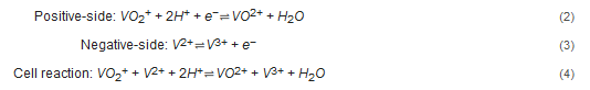
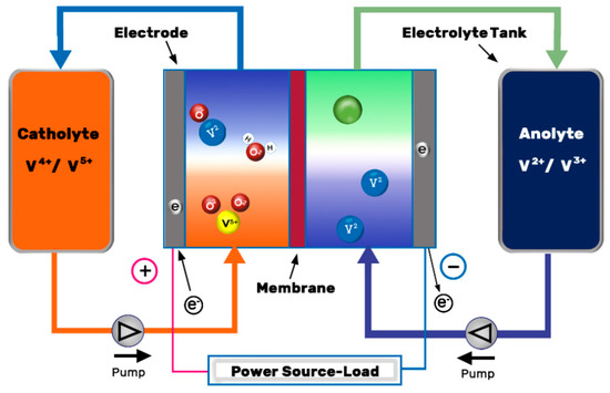
Figure 1. Schematic illustration of a VRFB. Redrawn from[2].
During the charge process, the VO2+ is oxidized to VO2+ at the cathode, while the V2+ is reduced to V3+ at the anode. The latter is the slowest of all four reactions, and the charge transfer resistance (CTR) of the positive half-cell at any SoC is negligible compared to the negative half-cell[3]. That is the reason why negative electrode electrochemical activity needs to be enhanced.
The equilibrium potential at one of the electrodes is calculated by the Nernst equation, defined by Equation (5), which describes the potential difference between the electrolyte and the electrode when no reaction is given inside the cell.
E=Eo+RTnFln(Coxidized speciesCreduced species⋅γoxidized speiesγreduced species)
where E is the potential difference and E0 is the standard reduction potential, R is the universal gas constant, T is the absolute temperature, n is the number of equivalents transferred per mole of species reduced or oxidized, F is Faraday’s constant, C is the ionic concentration, and γ is the activity coefficient of the species.
Each potential depends on the reactions defined in Equations (2) and (3), where the cathode’s (1) potential equals 1.0 V and anode’s (2) potential equals −0.26 V (both potentials are calculated using the Nernst equation). According to[4], the standard cell voltage is calculated by Equation (6):Eo+Eo=ΔV+−=V+−V−=1.0−(−0.26)=1.26 V
However, the real cell exhibits a standard cell voltage of E’o = 1.4 V when side effects (e.g., the Donnan potential at the membrane surface) are taken into consideration[4]. Furthermore, the OCV (Open-Circuit Voltage) varies with the SoC (State of Charge) of the electrodes, as shown in Equation (7)[5].SoC+SoC−(1−SoC+)(1−SoC−)
The ideal battery would be able to provide (discharge) the same energy that would have being stored up previously (charge), and the concept of efficiency is defined in three different ways[6]:
-
Coulombic Efficiency (CE)–or current efficiency–refers to the ratio of the total charge (in Amperes-hour) delivered by the battery to the charged stored up.
-
Voltage Efficiency (VE) is the ratio of the average discharged voltage to the average charged voltage.
-
The Energy Efficiency (EE) is defined in Equation (8) as the ratio of energy (in Watts-hour) discharged to charged energy. The EE is a key parameter of the battery’s overall performance and it can be related to the CE and VE as follows:ηE=ηC⋅ηV
The efficiency of the process is called Coulombic efficiency (or Current Efficiency) and depends on several factors: (1) an optimal electrolyte flow rate coupled with the electrochemical reaction rate that allows reactions to occur before the electrolyte returns to the storage tanks, (2) an efficient ion-selective membrane that prevents the cross-mixing of the vanadium ions, (3) an even distribution of the electrolyte along the electrode to avoid potential differences [7][8].
2. Main Parts of a Vanadium Redox Flow Battery
VRFB essentially consists of two key elements: the cell stacks, where several cells are assembled with the aim of converting chemical energy into electricity in a reversible process, and the tanks of electrolytes where energy is stored. In this Section, the main elements of a VRFB are discussed: the electrolyte, the carbon felt electrodes and the ion exchange membrane, respectively.
2.1. Electrolyte
In a VRFB, the electrolyte is composed of active species and supporting electrolytes. Traditional VRFBs use vanadium ions dissolved in sulphuric acid. The ideal redox couple would be one with high energy density, high nominal voltage and highly reversible redox kinetics[9]. Additionally, it would be desirable to be stable enough to allow a high DoD and SoC with high-capacity retention, ideally a symmetric system, as reported by Potash et al. [10], as well as environmentally sustainable. With the aim of improving the electrolyte technology, the development of organic active materials is presented as one of the most promising alternatives to vanadium technology even though it still lacks the necessary technological development[11]. Among the different families of organic compounds, the use of quinone pairs has been an object of intensive research for their use in flow batteries due to their stable and reversible nature in aqueous medium[12].
Furthermore, the supporting electrolyte, which includes organic or aqueous solvent, buffer and/or additives, is essential in the electrochemical behavior of the cell. Non-aqueous systems, a priori, have a wider potential window but aqueous systems present significant advantages. Leung et al. [11] reviewed lower cost and higher ionic mobility compared to non-aqueous electrolytes in addition to a lower environmental impact.
Among the different research works on aqueous organic electrolyte for redox flow systems (AORFB) reported in the literature there is a great disparity of data regarding energy density and stability (number of cycles)[13][14], with very few studies combining good results in both parameters, see the work of Liu et al.[15]. Choi et al.[16] covered in depth the main issues and challenges for VRFB electrolytes. Table 2 illustrates the main characteristics of different generations of VRFB, see Skyllas-Kazacos et al.[17].
Table 2. Main characteristics of different generations of VRFBs[17].
Table 2. Main characteristics of different generations of VRFBs[17].
| Generation | Max. Vanadium Concentration | Average Discharge Voltage (V) | Energy Density for 80% SOC Range (Wh/L) | Specific Energy for 80% SOC Range (Wh/kg) |
|---|---|---|---|---|
| V/V in H2SO4 | 1.5–3 M | 1.2 | 38–50 | 15–25 |
| V-halide in HCl/HBr | 2–3.5 M | 1.0 | 42–63 | 25–50 |
| V/V in HCl | 2.3 M | 1.2 | 35–40 a | 35–70 a |
| Fe/V | 1.5 M | 0.75 | 20–25 | 15–20 |
| Fe-V/2V | 1.5 M | 1.2 | 25–30 | 20–25 |
2.2. Electrodes
The electrode is one of the essential parts of a VRFB. It is responsible for capturing the electrons released in the chemical reactions, getting electric current from the cells when discharging, and providing electric current to the cell when charging. Despite the above-mentioned, the electrode does not participate in the reaction itself, but provides the active sites for the reactions to be given. The ideal electrode should fulfill the following characteristics [18].
-
To be chemically stable to bear the strong acids dissolved within the aqueous electrolyte.
-
To be made of a material with favorable electrocatalytic activity.
-
Provide a three-dimensional network structure with an optimal porosity in order to reach the optimal pressure-drop/reaction-rate equilibrium and a uniform electrolyte distribution.
-
Operate correctly in the voltage range of the battery.
-
To have excellent electrical conductivity for faster charge transfer reactions with low internal resistance.
-
Low cost.
In its most widespread configuration, the electrodes are used in the form of graphite felts (GF), a porous material through which the electrolyte flows. However, this material has a very poor wettability with aqueous electrolytes, so a pretreatment of the surface is usually given to achieve a sufficiently hydrophilic surface[19]. Table 2 classifies different types of electrodes studied in VRFB systems. Leung et al.[20] showed that removing the distance between the electrodes (i.e., the membrane, electrodes, and current collectors are in direct contact), reduces the internal ohmic resistance, facilitating mass transport and helping to minimize the voltage drop across the battery. This configuration, known as zero-gap flow field design (see Figure 2), has also been reported to achieve significantly high power densities[21].
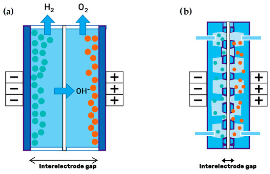
Figure 2. Electrode configuration: (a) Traditional setup; (b) zero-gap design of porous electrodes. Redrawn from[22].
Table 2. Electrodes used as negative and positive electrode components.
| Electrode Type | Charge/Discharge Potential Range (V) | Energy Efficiency (%) | Ref. |
|---|---|---|---|
| Negative Electrode | |||
| ZrO2 nanoparticle embedded carbon nanofibers | 0.7 and 1.7 | 73.3 | He et al. [23] |
| MnO2 nanosheet array-decorated carbon paper | 0.7 and 1.7 | 66.4 | Jiang et al. [24] |
| Titanium nitrite coated graphite felt | 0.9 and 1.7 | 77.4 | Wei et al.[25] |
| Flexible electrospun carbon nanofiber embedded with TiO2 | 0.7 and 1.7 | 75 | He et al. [26] |
| Electrospun nitrogen-doped carbon nanofiber | 0.7 and 1.7 | 72.8 | He et al.[27] |
| Positive Electrode | |||
| 3D graphene-nanowall-decorated carbon felts | 0.7 and 1.7 | 90 | Li et al. [28] |
| Graphene deposited carbon felt (CF) | 0.7 and 1.75 | 85 | Xia et al. [29] |
| Mn3O4/multi-walled carbon nanotube modified graphite felt | 0.7 and 1.7 | 84.6 | He et al. [30] |
| Co2-activated graphite felt | 0.7 and 1.6 | 84 | Chang et al. [31] |
| Biomass-derived electrode | 0.9 and 1.65 | 86.3 | Zhang et al. [32] |
To further improve the electrochemical properties (catalytic activity, electrical conductivity and wettability) and the useful life[3] (durability of the electrodes against chemical attack, overload, aging and corrosion) of carbon electrodes, different superficial treatments are under research[33]. Xia et al.[32] obtained promising results with a graphene modified carbon felt electrode with a coating process for a VRFB. Recently, Lv et al.[34] studied biomass carbon materials in order to obtain new low cost, renewable and sustainable energy storage systems. Reviews in this field can be found in the literature summarizing the recent progress on electrode materials and the development and application of carbon fiber in batteries[35][36].
There are two main electrode designs: the “flow-through”(FT) and the “flow-by”(FB) configuration, as illustrated in Figure 3 [32].
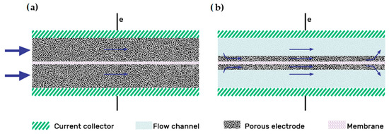
Figure 3. Electrode designs: (a) Flow-through; (b) Flow-by electrode configurations. Redrawn from[37].
The “flow-by” configuration was presented as the best flow field option long ago, as shown in the study of Trainham et al.[38][39]. Compared with the FT design, the addition of a flow field improves the distribution uniformity of the electrolyte through the electrode, particularly at flow rates [40][41]. Increasing the flow rate also increases the pumping power, but this effect is offset by the lowered overpotential, indicating that there is an optimal flow rate where maximum efficiency can be achieved [41]. In 2015, Reed et al. [40] experimented with a flow-through configuration VRFB at high density currents. Initially, they obtained too high temperatures related to the high pressure drop of the model; then, they decided to include a “flow-by” configuration with an interdigitated pattern, working at a higher flow rate while reducing the pressure drop. The new design reached an outstanding EE of 75% at 320 mA/cm2. In 2016 they carried out another flow-through/flow-by comparison, concluding that the FT configuration only outperformed the FB one at low flow rates (400 cc/min) [42]. The main advantages of the flow fields on the flow battery system summarize as follows[37]:
-
Using thinner electrodes implies lower ohmic losses (increasing the efficiency).
-
The enhancement of localized mass transfer in the porous electrode because the flow is driven through by the forced convection associated with the pressure drop along the flow field.
-
Higher limiting current density and peak power density.
2.3. Ion-Exchange Membranes
In general, the energy efficiency and cyclability of electrochemical cells with dissolved redox materials are intrinsically connected to the stability, ion conductivity and transport selectivity of the ion exchange membrane. The materials currently used for membranes are mostly material previously designed from other applications that have different functional requirements.
The use of alternative redox materials to vanadium (organic and/or organometallic), which presents complex phenomena of transport of ionic species, together with increasingly demanding operating conditions in redox flow batteries towards higher energy and current densities must be taken into account for the design of a new generation of membrane materials[43]. Most of redox based flow batteries (RFBs) employ polymeric membranes or separators, both anion exchange (AEM) and cation exchange (PEM) membranes.
Among the commercial options available in the market, perfluorinated membranes (Nafion®) are the most widespread for use in aqueous redox flow systems due to their excellent chemical stability and high ionic conductivity, see the work of Reed et al.[40]. Nonetheless, according to the study carried by Li et al. [35], these commercial alternatives have a low coulombic efficiency and a high cost. Its extensive use in fuel cells and also in vanadium technology has helped to check its viability for its use, which require high-performance membranes (fuel cells) and/or high stability against corrosive media. However, its efficiency in terms of ion selectivity for the vanadium system results in a loss of EC.
In the case of Anion Exchange Membranes (AEM), they offer better performance in terms of selectivity respect to the vanadium system, but are generally lower in conductivity than the PEMs previously mentioned. Several studies have reported this type of membrane in aqueous-organic systems[44][45]. In these cases and taking advantage of the lower requirements of the organic electrolyte, commercial membranes of lower cost are the most common used, see the work of Hu et al.[44]. According to Pezeshki et al. [46], membranes of the polyarylene type, either anionic or cationic, show remarkable properties in comparison to commercial membranes based on perfluorosulfonic polymers. However, chemical stability is usually a challenge for such materials.
Among the most interesting materials to manufacture membranes when chemical resistance and stability against oxidation are required, polybenzimidazole (PBI) is very promising. PBI membranes have been widely investigated in nanofiltration applications [47] and in high-temperature fuel cells[48]. PBI is able of absorbing acid and being protonated, developing anion exchange properties, as is the case of HMT-PBI[49], or for cation exchange, introducing sulfonic groups in the polymer structure[50]. PBI can also be built as an asymmetric porous membrane, see the work of Gubler et al.[43]. The review of Shi et al.[51] covered all the recent developments, challenges and future directions of membranes in non-aqueous redox flow batteries.
References
- Li, X.; Zhang, H.; Mai, Z.; Zhang, H.; Vankelecom, I. Ion exchange membranes for vanadium redox flow battery (VRB) applications. Energy Environ. Sci. 2011, 4, 1147, doi:10.1039/c0ee00770f.
- Esan, O.C.; Shi, X.; Pan, Z.; Huo, X.; An, L.; Zhao, T.S. Modeling and Simulation of Flow Batteries. Adv. Energy Mater. 2020, 2000758, doi:10.1002/aenm.202000758.
- Derr, I.; Bruns, M.; Langner, J.; Fetyan, A.; Melke, J.; Roth, C. Degradation of all-vanadium redox flow batteries (VRFB) investigated by electrochemical impedance and X-ray photoelectron spectroscopy: Part 2 electrochemical degradation. J. Power Sources 2016, 325, 351–359, doi:10.1016/j.jpowsour.2016.06.040.
- Knehr, K.W.; Kumbur, E.C. Open circuit voltage of vanadium redox flow batteries: Discrepancy between models and experiments. Electrochem. Commun. 2011, 13, 342–345, doi:10.1016/j.elecom.2011.01.020.
- Arenas, L.F.; de Ponce León, C.; Walsh, F.C. Engineering aspects of the design, construction and performance of modular redox flow batteries for energy storage. J. Energy Storage 2017, 11, 119–153, doi:10.1016/j.est.2017.02.007.
- Zhang, H.; Li, X.; Zhang, J. Redox Flow Batteries; CRC Press, Taylor & Francis Group: Boca Raton, Florida, USA, 2018; ISBN 978-1-4987-5394-4.
- Zhou, X.L.; Zhao, T.S.; An, L.; Wei, L.; Zhang, C. The use of polybenzimidazole membranes in vanadium redox flow batteries leading to increased coulombic efficiency and cycling performance. Electrochim. Acta 2015, 153, 492–498, doi:10.1016/j.electacta.2014.11.185.
- Yu, L.; Lin, F.; Xiao, W.; Xu, L.; Xi, J. Achieving efficient and inexpensive vanadium flow battery by combining CexZr1−xO2 electrocatalyst and hydrocarbon membrane. Chem. Eng. J. 2019, 356, 622–631, doi:10.1016/j.cej.2018.09.069.
- Yang, Z.; Tong, L.; Tabor, D.P.; Beh, E.S.; Goulet, M.-A.; De Porcellinis, D.; Aspuru-Guzik, A.; Gordon, R.G.; Aziz, M.J. Alkaline Benzoquinone Aqueous Flow Battery for Large-Scale Storage of Electrical Energy. Adv. Energy Mater. 2018, 8, 1702056, doi:10.1002/aenm.201702056.
- Potash, R.A.; McKone, J.R.; Conte, S.; Abruña, H.D. On the Benefits of a Symmetric Redox Flow Battery. J. Electrochem. Soc. 2016, 163, A338–A344, doi:10.1149/2.0971602jes.
- Leung, P.; Shah, A.A.; Sanz, L.; Flox, C.; Morante, J.R.; Xu, Q.; Mohamed, M.R.; Ponce de León, C.; Walsh, F.C. Recent developments in organic redox flow batteries: A critical review. J. Power Sources 2017, 360, 243–283, doi:10.1016/j.jpowsour.2017.05.057.
- Winsberg, J.; Hagemann, T.; Janoschka, T.; Hager, M.D.; Schubert, U.S. Redox-Flow Batteries: From Metals to Organic Redox-Active Materials. Angew. Chem. Int. Ed. 2017, 56, 686–711, doi:10.1002/anie.201604925.
- Chalamala, B.R.; Soundappan, T.; Fisher, G.R.; Anstey, M.R.; Viswanathan, V.V.; Perry, M.L. Redox Flow Batteries: An Engineering Perspective. Proc. IEEE 2014, 102, 976–999, doi:10.1109/JPROC.2014.2320317.
- Kwabi, D.G.; Lin, K.; Ji, Y.; Kerr, E.F.; Goulet, M.-A.; De Porcellinis, D.; Tabor, D.P.; Pollack, D.A.; Aspuru-Guzik, A.; Gordon, R.G.; et al. Alkaline Quinone Flow Battery with Long Lifetime at pH 12. Joule 2018, 2, 1894–1906, doi:10.1016/j.joule.2018.07.005.
- Liu, Y. A Long-Lifetime All-Organic Aqueous Flow Battery Utilizing TMAP-TEMPO Radical; Chem 2019, 5, 1861–1870.
- Choi, C.; Kim, S.; Kim, R.; Choi, Y.; Kim, S.; Jung, H.; Yang, J.H.; Kim, H.-T. A review of vanadium electrolytes for vanadium redox flow batteries. Renew. Sustain. Energy Rev. 2017, 69, 263–274, doi:10.1016/j.rser.2016.11.188.
- Skyllas-Kazacos, M.; McCann, J.F. Vanadium redox flow batteries (VRBs) for medium- and large-scale energy storage. In Advances in Batteries for Medium and Large-Scale Energy Storage; Elsevier: Amsterdam, The Netherlands, 2015; pp. 329–386. ISBN 978-1-78242-013-2.
- Kim, K.J.; Park, M.-S.; Kim, Y.-J.; Kim, J.H.; Dou, S.X.; Skyllas-Kazacos, M. A technology review of electrodes and reaction mechanisms in vanadium redox flow batteries. J. Mater. Chem. A 2015, 3, 16913–16933, doi:10.1039/C5TA02613J.
- Castañeda, L.F.; Walsh, F.C.; Nava, J.L.; de Ponce León, C. Graphite felt as a versatile electrode material: Properties, reaction environment, performance and applications. Electrochim. Acta 2017, 258, 1115–1139, doi:10.1016/j.electacta.2017.11.165.
- Leung, P.K. A mixed acid based vanadium-cerium redox flow battery with a zero-gap serpentine architecture. J. Power Sources 2015, 8, 651–658.
- Abbas, S.; Mehboob, S.; Shin, H.-J.; Han, O.H.; Ha, H.Y. Highly functionalized nanoporous thin carbon paper electrodes for high energy density of zero-gap vanadium redox flow battery. Chem. Eng. J. 2019, 378, 122190, doi:10.1016/j.cej.2019.122190.
- Phillips, R.; Dunnill, C.W. Zero Gap Alkaline Electrolysis Cell Design for Renewable Energy Storage as Hydrogen Gas. RSC Adv. 2016, 6, 100643–100651, doi:10.1039/C6RA22242K.
- He, Z.; Li, M.; Li, Y.; Li, C.; Yi, Z.; Zhu, J.; Dai, L.; Meng, W.; Zhou, H.; Wang, L. ZrO2 nanoparticle embedded carbon nanofibers by electrospinning technique as advanced negative electrode materials for vanadium redox flow battery. Electrochim. Acta 2019, 309, 166–176, doi:10.1016/j.electacta.2019.04.100.
- Jiang, Y.; Feng, X.; Cheng, G.; Li, Y.; Li, C.; He, Z.; Zhu, J.; Meng, W.; Zhou, H.; Dai, L.; et al. Electrocatalytic activity of MnO2 nanosheet array-decorated carbon paper as superior negative electrode for vanadium redox flow batteries. Electrochim. Acta 2019, 322, 134754, doi:10.1016/j.electacta.2019.134754.
- Wei, L.; Zhao, T.S.; Zeng, L.; Zeng, Y.K.; Jiang, H.R. Highly catalytic and stabilized titanium nitride nanowire array-decorated graphite felt electrodes for all vanadium redox flow batteries. J. Power Sources 2017, 341, 318–326, doi:10.1016/j.jpowsour.2016.12.016.
- He, Z.; Li, M.; Li, Y.; Zhu, J.; Jiang, Y.; Meng, W.; Zhou, H.; Wang, L.; Dai, L. Flexible electrospun carbon nanofiber embedded with TiO2 as excellent negative electrode for vanadium redox flow battery. Electrochim. Acta 2018, 281, 601–610, doi:10.1016/j.electacta.2018.06.011.
- He, Z.; Li, M.; Li, Y.; Wang, L.; Zhu, J.; Meng, W.; Li, C.; Zhou, H.; Dai, L. Electrospun nitrogen-doped carbon nanofiber as negative electrode for vanadium redox flow battery. Appl. Surf. Sci. 2019, 469, 423–430, doi:10.1016/j.apsusc.2018.10.220.
- Li, W.; Zhang, Z.; Tang, Y.; Bian, H.; Ng, T.; Zhang, W.; Lee, C. Graphene‐Nanowall‐Decorated Carbon Felt with Excellent Electrochemical Activity Toward VO2+ /VO2+ Couple for All Vanadium Redox Flow Battery. Adv. Sci. 2016, 3, 1500276, doi:10.1002/advs.201500276.
- He, Z.; Dai, L.; Liu, S.; Wang, L.; Li, C. Mn3O4 anchored on carbon nanotubes as an electrode reaction catalyst of V(IV)/V(V) couple for vanadium redox flow batteries. Electrochim. Acta 2015, 176, 1434–1440, doi:10.1016/j.electacta.2015.07.067.
- Chang, Y.-C.; Chen, J.-Y.; Kabtamu, D.M.; Lin, G.-Y.; Hsu, N.-Y.; Chou, Y.-S.; Wei, H.-J.; Wang, C.-H. High efficiency of CO2 -activated graphite felt as electrode for vanadium redox flow battery application. J. Power Sources 2017, 364, 1–8, doi:10.1016/j.jpowsour.2017.07.103.
- Zhang, Z.H.; Zhao, T.S.; Bai, B.F.; Zeng, L.; Wei, L. A highly active biomass-derived electrode for all vanadium redox flow batteries. Electrochim. Acta 2017, 248, 197–205, doi:10.1016/j.electacta.2017.07.129.
- Xia, L.; Zhang, Q.; Wu, C.; Liu, Y.; Ding, M.; Ye, J.; Cheng, Y.; Jia, C. Graphene coated carbon felt as a high-performance electrode for all vanadium redox flow batteries. Surf. Coat. Technol. 2019, 358, 153–158, doi:10.1016/j.surfcoat.2018.11.024.
- Eifert, L.; Banerjee, R.; Jusys, Z.; Zeis, R. Characterization of Carbon Felt Electrodes for Vanadium Redox Flow Batteries: Impact of Treatment Methods. J. Electrochem. Soc. 2018, 165, A2577–A2586, doi:10.1149/2.0531811jes.
- Lv, Y. Application of porous biomass carbon materials in vanadium redox flow battery. J. Colloid Interface Sci. 2020, 10, 434–443.
- Gencten, M.; Sahin, Y. A critical review on progress of the electrode materials of vanadium redox flow battery. Int. J. Energy Res. 2020, 44, 7903–7923, doi:10.1002/er.5487.
- Yang, S. Development and application of carbon fiber in batteries. Chem. Eng. J. 2020, 20. 384:123294.
- Ke, X.; Prahl, J.M.; Alexander, J.I.D.; Wainright, J.S.; Zawodzinski, T.A.; Savinell, R.F. Rechargeable redox flow batteries: Flow fields, stacks and design considerations. Chem. Soc. Rev. 2018, 47, 8721–8743, doi:10.1039/C8CS00072G.
- Trainham, J.A. A comparison between flow-through and flow-by porous electrodes for redox energy storage. Electrochim. Acta 1981, 26, 455–469, doi:10.1016/0013-4686(81)87024-7.
- Reed, D.; Thomsen, E.; Li, B.; Wang, W.; Nie, Z.; Koeppel, B.; Kizewski, J.; Sprenkle, V. Stack Developments in a kW Class All Vanadium Mixed Acid Redox Flow Battery at the Pacific Northwest National Laboratory. J. Electrochem. Soc. 2016, 163, A5211–A5219, doi:10.1149/2.0281601jes.
- Reed, D.; Thomsen, E.; Wang, W.; Nie, Z.; Li, B.; Wei, X.; Koeppel, B.; Sprenkle, V. Performance of Nafion® N115, Nafion® NR-212, and Nafion® NR-211 in a 1 kW class all vanadium mixed acid redox flow battery. J. Power Sources 2015, 285, 425–430, doi:10.1016/j.jpowsour.2015.03.099.
- Xu, Q.; Zhao, T.S.; Leung, P.K. Numerical investigations of flow field designs for vanadium redox flow batteries. Appl. Energy 2013, 105, 47–56, doi:10.1016/j.apenergy.2012.12.041.
- Reed, D.; Thomsen, E.; Li, B.; Wang, W.; Nie, Z.; Koeppel, B.; Kizewski, J.; Sprenkle, V. Stack Developments in a kW Class All Vanadium Mixed Acid Redox Flow Battery at the Pacific Northwest National Laboratory. J. Electrochem. Soc. 2016, 163, A5211–A5219, doi:10.1149/2.0281601jes
- Gubler, L. Membranes and separators for redox flow batteries. Curr. Opin. Electrochem. 2019, 18, 31–36, doi:10.1016/j.coelec.2019.08.007.
- Hu, B.; DeBruler, C.; Rhodes, Z.; Liu, T.L. Long-Cycling Aqueous Organic Redox Flow Battery (AORFB) toward Sustainable and Safe Energy Storage. J. Am. Chem. Soc. 2017, 139, 1207–1214, doi:10.1021/jacs.6b10984.
- Li, Y.; Liu, Y.; Xu, Z.; Yang, Z. Poly(phenylene oxide)-Based Ion-Exchange Membranes for Aqueous Organic Redox Flow Battery. Ind. Eng. Chem. Res. 2019, 58, 10707–10712, doi:10.1021/acs.iecr.9b01377.
- Pezeshki, A.M.; Tang, Z.J.; Fujimoto, C.; Zawodzinski, T.A. Full Cell Study of Diels Alder Poly(phenylene) Anion and Cation Exchange Membranes in Vanadium Redox Flow Batteries. J. Electrochem. Soc. 2016, 10, A5154.
- Wang, K.; Chung, T. Fabrication of polybenzimidazole (PBI) nanofiltration hollow fiber membranes for removal of chromate. J. Membr. Sci. 2006, 281, 307–315, doi:10.1016/j.memsci.2006.03.045.
- Hou, H.; Sun, G.; He, R.; Sun, B.; Jin, W.; Liu, H.; Xin, Q. Alkali doped polybenzimidazole membrane for alkaline direct methanol fuel cell. Int. J. Hydrog. Energy 2008, S036031990801152X, doi:10.1016/j.ijhydene.2008.09.023.
- Shanahan, B.; Böhm, T.; Britton, B.; Holdcroft, S.; Zengerle, R.; Vierrath, S.; Thiele, S.; Breitwieser, M. 30 μm thin hexamethyl-p-terphenyl poly(benzimidazolium) anion exchange membrane for vanadium redox flow batteries. Electrochem. Commun. 2019, 102, 37–40, doi:10.1016/j.elecom.2019.03.016.
- Wang, L.; Pingitore, A.T.; Xie, W.; Yang, Z.; Perry, M.L.; Benicewicz, B.C. Sulfonated PBI Gel Membranes for Redox Flow Batteries. J. Electrochem. Soc. 2019, 166, A1449–A1455, doi:10.1149/2.0471908jes.
- Shi, Y.; Eze, C.; Xiong, B.; He, W.; Zhang, H.; Lim, T.M.; Ukil, A.; Zhao, J. Recent development of membrane for vanadium redox flow battery applications: A review. Appl. Energy 2019, 238, 202–224, doi:10.1016/j.apenergy.2018.12.087.


