 +1 credit
| Version | Summary | Created by | Modification | Content Size | Created at | Operation |
|---|---|---|---|---|---|---|
| 1 | Changhwan Shin | + 2783 word(s) | 2783 | 2020-12-29 07:19:39 | | | |
| 2 | Nicole Yin | Meta information modification | 2783 | 2021-01-08 07:53:21 | | |
Video Upload Options
Capacitors with superior characteristics (called supercapacitors), which are unavailable in conventional batteries, exhibit excellent functionality in many areas, including power density, charge/discharge cycles, operation over a wide temperature range, and reliability, which have been noted as limits of batteries.
1. Introduction
There are various requirements to implement next-generation energy storage systems (ESSs), but to date, some systems to satisfy certain conditions remain nonexistent[1]. Of these, capacitors using the extreme surface area and distance from the electrode to the charged ions layer on the electrolyte have particularly attracted attention owing to their superior specific power. Capacitors with superior characteristics (called supercapacitors), which are unavailable in conventional batteries, exhibit excellent functionality in many areas, including power density, charge/discharge cycles, operation over a wide temperature range, and reliability, which have been noted as limits of batteries[1][2][3][4][5][6]. However, based on energy density, it is evident that supercapacitors must be studied intrinsically.
2. Theory of the Electrochemical Double Layer
As the name itself indicates, supercapacitors are devices that maximize the capacitance of conventional capacitors. These devices based on physical charge storage with electrical operation exhibit a charge output like capacitors; thus, the capacitance “C” depends on the dielectric constant εr of the electrolyte, the effective thickness “d” of the charge separation layer from electrodes, and the accessible surface “A” through the distance between the electric layers based on Helmholtz theory and the porous structure[7].
In conventional capacitors, surface area A is a two-dimensional single-planar electrode, while the supercapacitor is a three-dimensional porous electrode—i.e., the surface area is maximized. The dielectric layer of a supercapacitor comprises a single or several molecular layers, so “d” is only a small molecular distance, ranging from a few Å to several Å. This is a huge difference, considering that an electrostatic capacitor has an insulator layer that reaches up to several microns.
The charge separation layer is formed with ions when a charged object is placed in an electrolyte. The mutual interfacial structure between the electrodes creates a certain structure. The balancing counter charge on the charged surface of this object is formed correspondingly in the electrode and concentrated near the surface. Various theories have been proposed to explain the structure wherein charges are formed, and a complete theory explaining all the mechanical contents remains undetermined. There are theories for understanding the charge separation layer, as represented in Figure 1.
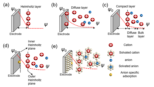
Figure 1. Models of the electrochemical double layer. (a) Helmholtz model; (b) Gouy–Chapman or diffuse model; (c) Stern model; (d) Grahame model; (e) Bockris, Devanathan, and Muller model[8][9][10].
The Helmholtz model is the first theory to provide an approximation for the arrangement between the electrode and layer of ions called the Helmholtz layer or plane with a finite distance. However, there are some problems with interactions that occur further away from the electrode which include the electrolyte concentration and all the given environments, besides the double layer arising from the interface (Figure 2a)[8][11]. Chapman did not take this into account and proposed an electrical double-layer theory and considered the applied potential and electrolyte concentration. Gouy suggested that a layer of positive ionic charge that counteracts the charge affecting the charged electrode appears in the electrolyte surrounding the charged solid, but that ions did not appear only on the surface with a diffusion layer based on the Boltzmann distribution that demonstrated the concentration of charged ions with the counter ions near the surface. This is called the diffuse layer. However, this model also has problems. Because ions are expressed as point charges, the specific size of the ion is not considered. The theory does not recognize that the finite space of ions cannot exist near the electrode. Secondly, it fails when applied to highly charged double layers (Figure 2b)[8][12][13][14][15][16][17]. Stern modified the diffusion double layer to integrate the theories of Helmholtz and Gouy–Chapman and proposed the compact layer presented by the improved understanding of the architectures of the ions with a specific size and limiting space between the electrode and electrolyte, but also extended the diffusion layer to the bulk layer. This distance is generally considered as the radius of the ions. Consequently, the potential charges and concentration of the diffusion portion of the layer are sufficiently low to justify treating ions with point charges (Figure 2c)[8][18][19][20]. Grahame developed the theory of electrical double layers based on four regions—the inner Helmholtz plane in front of the electrode with small molecular distances; the outer Helmholtz plane, which consists of Helmholtz layers; the diffusion region; and the bulk region suggested by Stern. The theory of specific adsorption was applied. This bond occurs on the surface of the metal electrode. The negative ions are adsorbed on the surface of the electrode regardless of its charge, not by the electrical force, but via chemical interaction. The ions referred to as ghost ions act as pseudocapacitive particles. Cations rarely stick to the electrode. The adsorption of ghost ions would be reduced while keeping the solution and electrodes clean. The capacitor centered on the reaction by specifically adsorbed ions is called a pseudocapacitor, which is found at the interface between the electrolyte and electrode (Figure 2d)[8][9][10]. Bockris, Devanathan, and Muller’s model shows a phenomenon for the preponderance of solvent molecules around the interface. Solvated molecules, anions, cations, and electrodes were suggested, and the dipole moment was considered for both the charge separation and diffusion layers. The model is acceptable for the values applied to understand high-current-power EDLCs. However, the concept cannot perfectly explain carbon-based models with porous structures (Figure 2e)[8][21].
3. Variation of Capacitance According to Pore Size and Structure
Although the theory of electric double layers on plane surfaces has been clarified, problems arise when applying electric double layers to pores in actual spaces. The characteristics of ion electrical adsorption in porous structures make the process of charge storage difficult to deal with. Understanding the principle of charge storage through the formation of layers by cations and anions remains insufficient to explain experimental results when applied in nanopores. Generally, the inverse effect of pore size on capacitance is also known. Ions have different movement patterns with pores compared to the surface or bulk region.
The specific surface area, which exhibits a connection between the pore sizes, is important in order to understand its impact on specific capacitance. Additionally, it has been an attractive subject of study to numerous research groups in the past two decades. The capacitance generally increases proportionally to the surface area, but in the micropore region a difference in increasing value occurs. As the movement of ions has architectures with a finite size, the potential charges are greatly affected by the size of the pores. Each ion that plays a role in the storage of charge has a specific size, thereby allowing access to structures above a certain scale. Even if the surface area is increased, in regions where the pore size is too small for the solvated ion to approach it does not fully contribute to the layer, which should interact with electrodes. The specific and volumetric capacitance values indicate significant increases and are inversely commensurate to the nonlinear proportion depending on the chlorination temperature, which is largely involved in pore size control[22][23].
It is important to adjust the temperature, density, and intensity values for each material. The targets that constitute the electric double layer with the ions in the electrode layer are activated carbon and graphene, which have two-dimensional structures, and carbon nanotubes (CNTs), which have three-dimensional structures. Activated carbon changes the pore size depending on the temperature. Because the size of the pores determines the number of ions that can pass through the bilayer, if the conductivity is greatest at one point in the nano-meter range, then it decreases rapidly at higher and lower temperatures based on that state[22][23][24][25][26][27].
The reasons for this are as follows. First, when they are smaller than the largest point, solvated ions do not have the minimum length to form a double layer. That is, the optimal pore size may vary depending on the scale of the electrolyte ions (Figure 3)[25][26][27]. According to their characteristics, there is a change in the interaction mechanism between the electrodes and ions. To understand this phenomenon, micropores are analyzed from various perspectives. The first aspect concerns layer formation as a cylinder (Figure 3).
There are many inquiries regarding the interaction between the electrolyte and the electrode fabricated with carbon material to adequately describe the electrostatic capacity depending on the pore shape and size. The analysis of capacitance for a cylindrical model is as follows, and it is analyzed by Gauss’s law (Figure 3c):
|
|
(1) |
|
|
(2) |
|
. |
(3) |
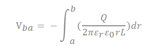
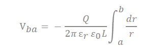
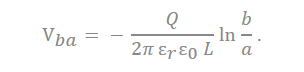
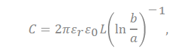
In the equation, “ ” represents the dielectric constant of the electrolyte, the permittivity of a vacuum is expressed as “ ”, the distance from the center of the pore to the cation is expressed “a”, and the radius of the pore is expressed as “b”.
|
|
(4) |
|
|
(5) |
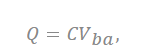
where the total charge on the cylinder is expressed as “Q”, and C represents the capacitance of the supercapacitor. This is applied at a distance of ~0 nm or less from the electrode to ions. Depending on the size of the pores, the number of ions that can contribute to the capacitance and the size of the layer of ions change (Figure 3b).
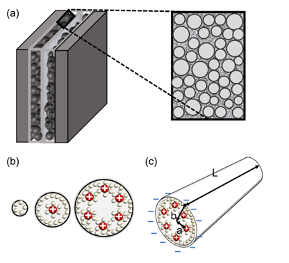
Figure 3. (a) Brief structure of a supercapacitor with a view of cylindrical theory (endohedral capacitors/electric double-cylinder capacitor), (b) shape of the electrolyte ion placed and the cylindrical electrode according to the pore size. The first picture shows that the ions are not very involved in charge storage because they have a very small pore structure. The second figure shows one ion interacting with an electrode to store charge. The third figure shows more ions forming the same layer and acting on the electrode. (c) The shape of pores observed in a three-dimensional shape; “a” is the distance from the center to a layer of several ions, the radius of the pores is expressed as “b”, and the cylinder length is expressed as “L”[7][28][29].
The second model tries to understand the interaction between ions and electrodes based on slits. Depending on the interval between the slits, the types wherein the ions of the electrolyte with electrode contribute are different which is described on Figure 4b–f[28][29].
If it is larger than point a in Figure 4g, the distance between the electrode and ions increases because one electrode and several solvation ions constitute a double layer. Here, solvation ions act as an insulator, and the distance is applied to the capacitor’s width of the dielectric layer. When the pore size is greater than a certain spot b in Figure 4g, the electrode pores and the layer of ions that can be formed start to increase; thus, the capacitance starts to increase again[22]. Nanopores sometimes have minimal spaces to form electrical layers with solvated ions (Figure 4b) as well as electrical layers with solvated ions (Figure 4c). If the pore size is less than or equal to a, (b) → (c) applies. (d) represents the case of solvated ions with nanopores having extra space to form an electrical layer, and (e) shows that the nanopore has sufficient solvated ions to form an electrical layer with each electrode and that there is adequate space in each electrode. If the pore size exceeds a and b or less, (c) → (d) is applicable. If the pore size is greater than b, (e) → (f) is applied (Figure 4)[22][23][25].
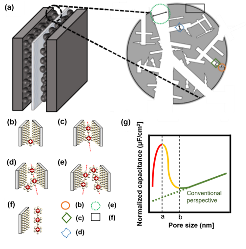
Figure 4. (a) Brief structure of activated carbon particles with various pore sizes, not based on a circle, but based on the electrode theory of walls and walls. (b) Nanopores do not have the minimum space required to form an electrical layer with solvated ions, (c) nanopores have minimal space to form an electrical layer with solvated ions, (d) nanopores have extra space to form an electrical layer with solvated ions, (e) nanopores have sufficient space for each electrode such that solvated ions can form an electrical layer with each electrode, (f) electric layer for carbon grain at the surface, (g) schematic diagram of normalized capacitance according to pore size. When the pore size is less than or equal to a, which is indicated by a red-colored line, (b,c) is applicable, and when the pore size is more than a and less than or equal to b, which is indicated by a yellow-colored line, (c,d) is applicable. If the pore size is larger than b, which is indicated by a green-colored line with a conventional view, (e,f) is applied[8][22][23][25].
Depending on how the capacitor interacts with the carbon surface of the counter ion, these EDLCs can also be divided into endoderm and ectoderm capacitors, distinguished by the way the carbon surface interacts with the charged molecule layer. In the endoderm, counter ions enter the pores and form EDLs with the external electrodes. This type of charge accumulation is observed for nanoporous carbons with negative surface curvatures. These structures are conventionally shown on the activated carbon, carbide-derived carbon, and template carbon. In the case of an outer surface capacitor, it was observed that ions existed on the outer surface of the carbon particles[7].
The third model tries to interpret both theories with a cylindrical and slit structure (Figure 5). This theory suggests that there are significant cylinders that affect the normalized capacitance and slits which are based on micropores with inaccessible architectures according to the size of the pores. As this theory combined conventional theories about micro and macropores, it is more compatible to interpret lots of phenomena. The cylinder radius size plays a role of consolidation with capacitance, since the pore size reaches certain values. Additionally, the size of the slits affects the normalized capacitance, since the size is changed with various ranges[30][31]. Both the macropore and micropore structure is captured by scanning electron microscopy (SEM) images of highly pores activated carbons (HAPC). The images by SEM are 1 μm to 10 μm with different elements (Figure 6)[30].
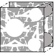
Figure 5. An analysis model for the theory of nanopores, showing a model that combines the theory of a structure made of cylinders and micropores8][22][23][25]28][31].
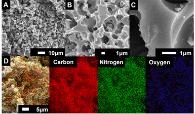
Figure 6. (A−C) Macro/micropole-dominated carbon on SEM (scanning electron microscope) images with different scale (10 μm and 1μm) and (D) element mapping of highly porous activated carbon[30]. Reprinted with permission from Ref.[30]. Copyright 2017 American Chemical Society.
Carbon materials with positively curved surfaces, such as nanofibers and carbon ions, exhibit certain types of behaviors. Since the curvature of graphene is zero, it does not belong to the first two categories, and it is classified as a graphene capacitor itself.
The capacitance in the plane is shown in series with the electrical double layer, wherein “a0” is few molecular distances which are radii to solvated cation, the half of distance from the slit is expressed as “b”, and “deff” is the effective separation distance between the electrode surface and the oppositely charged ions, which do not simply point charges, and the ionic radii place a role of the location of the charge densities.
In the recently discovered carbon, a realistic approximation of the pore shape is a slit rather than a cylinder. Accordingly, a polarity located in-between two electrodes separated by a single layer of charge has been proposed. The capacitive formula for the sandwich capacitor, which is located in between two electrodes of the same polarity and is formed with a layer formed with a counter ion separated with 2b, which is indicated in the pore width (Figure 7). Because the counter electrode shares the total net charge of the opposite charged ions, slit capacitors can be considered as two capacitors in parallel, represented by the left and right-hand electrodes and the charged molecule layer in the middle, as shown in Figure 7. Therefore, the total capacitance Ctot is calculated as follows[27][32]:
|
. |
(6) |
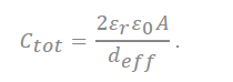
In the equation, represents the dielectric constant of electrolyte, is the permittivity of a vacuum, and the surface area of the electrode is represented as A.
|
|
(7) |
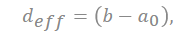
where deff is the effective separation distance between the electrode surface and the opposite charged ions, and the total capacitance of the capacitor is obtained as follows:
|
|
(8) |
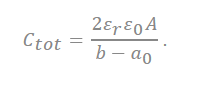
All the analyses were performed in one region, similar to the interaction method between the dielectric layer and the electrode, which was performed in a typical capacitor. The theory notified that the corrections of charge separation by the locations of charge densities are extremely important in producing a reliable capacitance model, especially for micropores. However, as the present model is derived for parallel plates, we should notice that a precise structure of the electrode was not considered for the reason of feasibility. The areal total capacitance of the system should be obtained[27].
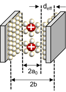
Figure 7. Schematic diagram of a capacitor formed by a solvated cation with a negative polarity located in the middle of two electrodes separated by a single layer of charge[22][27][33].
References
- John R. Miller; Patrice Simon; MATERIALS SCIENCE: Electrochemical Capacitors for Energy Management. Science 2008, 321, 651-652, 10.1126/science.1158736.
- Kötz, R.; Carlen, M. Principles and applications of electrochemical capacitors. Electrochim. Acta 2000, 45, 2483–2498.
- Liu, J.; Wang, J.; Xu, C.; Jiang, H.; Li, C.; Zhang, L.; Lin, J.; Shen, Z.X. Advanced Energy Storage Devices: Basic Principles, Analytical Methods, and Rational Materials Design. Adv. Sci. (Weinh) 2018, 5, 1700322.
- Iro, Z.S. A Brief Review on Electrode Materials for Supercapacitor. Int. J. Electrochem. Sci. 2016, 11, 10628–10643.
- Laidler, K.J. The development of the Arrhenius equation. J. Chem. Educ. 1984, 61, 494.
- Ma, S.; Jiang, M.; Tao, P.; Song, C.; Wu, J.; Wang, J.; Deng, T.; Shang, W. Temperature effect and thermal impact in lithium-ion batteries: A review. Prog. Nat. Sci. Mater. Int. 2018, 28, 653–666.
- Ratha, S.; Samantara, A.K. Supercapacitor: Instrumentation, Measurement and Performance Evaluation Techniques; Springer: Berlin/Heidelberg, Germany, 2018.
- Endo, M.; Takeda, T.; Kim, Y.; Koshiba, K.; Ishii, K. High power electric double layer capacitor (EDLC’s); from operating principle to pore size control in advanced activated carbons. Carbon Lett. 2001, 1, 117–128.
- Grahame, D.C. The electrical double layer and the theory of electrocapillarity. Chem. Rev. 1947, 41, 441–501.
- Grahame, D.C. Thermodynamic Properties of the Electrical Double Layer; Amherst College: Amherst, MA, USA, 1954.
- H. Helmholtz; Studien über electrische Grenzschichten. Annalen der Physik 2007, 243, 337-382, 10.1002/andp.18792430702.
- Gouy, M. Sur la constitution de la charge électrique à la surface d’un électrolyte. J. Phys. Theor. Appl. 1910, 9, 457–468.
- Gupta, A.; Stone, H.A. Electrical double layers: Effects of asymmetry in electrolyte valence on steric effects, dielectric decrement, and ion–ion correlations. Langmuir 2018, 34, 11971–11985.
- Chapman, D.L. LI. A contribution to the theory of electrocapillarity. Lond. Edinb. Dublin Philos. Mag. J. Sci. 1913, 25, 475–481.
- Bolt, G. Analysis of the validity of the Gouy-Chapman theory of the electric double layer. J. Colloid Sci. 1955, 10, 206–218.
- Outhwaite, C.W.; Bhuiyan, L.B.; Levine, S. Theory of the electric double layer using a modified poisson–boltzman equation. J. Chem. Soc. Faraday Trans. 2 Mol. Chem. Phys. 1980, 76, 1388–1408.
- Valleau, J.; Torrie, G. The electrical double layer. III. Modified Gouy− Chapman theory with unequal ion sizes. J. Chem. Phys. 1982, 76, 4623–4630.
- Stern, O. The theory of the electrolytic double-layer. Z. Elektrochem. 1924, 30, 1014–1020.
- Chan, D.Y.; Healy, T.W.; Supasiti, T.; Usui, S. Electrical double layer interactions between dissimilar oxide surfaces with charge regulation and Stern–Grahame layers. J. Colloid Interface Sci. 2006, 296, 150–158.
- Uvarov, N. Estimation of the surface potential in superionic oxide conductors using the Stern model. Solid State Ion. 2008, 179, 783–787.
- Bockris, J.M.; Devanathan, M.; Müller, K. On the structure of charged interfaces. In Electrochemistry; Elsevier: Amsterdam, The Netherlands, 1965; pp. 832–863.
- Chmiola, J.; Yushin, G.; Gogotsi, Y.; Portet, C.; Simon, P.; Taberna, P.-L. Anomalous increase in carbon capacitance at pore sizes less than 1 nanometer. Science 2006, 313, 1760–1763.
- Simon, P.; Burke, A. Nanostructured carbons: Double-layer capacitance and more. Electrochem. Soc. Interface 2008, 17, 38.
- Barbieri, O.; Hahn, M.; Herzog, A.; Kötz, R. Capacitance limits of high surface area activated carbons for double layer capacitors. Carbon 2005, 43, 1303–1310.
- Largeot, C.; Portet, C.; Chmiola, J.; Taberna, P.-L.; Gogotsi, Y.; Simon, P. Relation between the ion size and pore size for an electric double-layer capacitor. J. Am. Chem. Soc. 2008, 130, 2730–2731.
- Chmiola, J.; Largeot, C.; Taberna, P.L.; Simon, P.; Gogotsi, Y. Desolvation of ions in subnanometer pores and its effect on capacitance and double-layer theory. Angew. Chem. Int. Ed. 2008, 47, 3392–3395.
- Feng, G.; Qiao, R.; Huang, J.; Sumpter, B.G.; Meunier, V. Ion distribution in electrified micropores and its role in the anomalous enhancement of capacitance. ACS Nano 2010, 4, 2382–2390.
- Huang, J.; Sumpter, B.G.; Meunier, V. A universal model for nanoporous carbon supercapacitors applicable to diverse pore regimes, carbon materials, and electrolytes. Chem. A Eur. J. 2008, 14, 6614–6626.
- Huang, J.; Sumpter, B.G.; Meunier, V. Theoretical model for nanoporous carbon supercapacitors. Angew. Chem. Int. Ed. 2008, 47, 520–524.
- Tang, K.; Chang, J.; Cao, H.; Su, C.; Li, Y.; Zhang, Z.; Zhang, Y. Macropore-and micropore-dominated carbon derived from poly (vinyl alcohol) and polyvinylpyrrolidone for supercapacitor and capacitive deionization. ACS Sustain. Chem. Eng. 2017, 5, 11324–11333.
- Liu, H.J.; Wang, J.; Wang, C.X.; Xia, Y.Y. Ordered Hierarchical Mesoporous/Microporous Carbon Derived from Mesoporous Titanium-Carbide/Carbon Composites and its Electrochemical Performance in Supercapacitor. Adv. Energy Mater. 2011, 1, 1101–1108.
- Sanliang Zhang; Ning Pan; Supercapacitors Performance Evaluation. Advanced Energy Materials 2014, 5, 1401401, 10.1002/aenm.201401401.
- Michael Fröba; Frank Hoffmann; Michael Fröba; Insights into the influence of the pore size and surface area of activated carbons on the energy storage of electric double layer capacitors with a new potentially universally applicable capacitor model. Physical Chemistry Chemical Physics 2019, 21, 3122-3133, 10.1039/c8cp06443a.

