Your browser does not fully support modern features. Please upgrade for a smoother experience.

Submitted Successfully!
Thank you for your contribution! You can also upload a video entry or images related to this topic.
For video creation, please contact our Academic Video Service.
| Version | Summary | Created by | Modification | Content Size | Created at | Operation |
|---|---|---|---|---|---|---|
| 1 | Junior Diamant Ngando Ebba | -- | 2015 | 2024-03-25 16:22:12 | | | |
| 2 | Lindsay Dong | + 40 word(s) | 2055 | 2024-03-26 02:21:06 | | |
Video Upload Options
We provide professional Academic Video Service to translate complex research into visually appealing presentations. Would you like to try it?
Cite
If you have any further questions, please contact Encyclopedia Editorial Office.
Ngando Ebba, J.D.; Camara, M.B.; Doumbia, M.L.; Dakyo, B.; Song-Manguelle, J. Large-Scale Hydrogen Production Systems Using Marine Renewable Energies. Encyclopedia. Available online: https://encyclopedia.pub/entry/56478 (accessed on 08 February 2026).
Ngando Ebba JD, Camara MB, Doumbia ML, Dakyo B, Song-Manguelle J. Large-Scale Hydrogen Production Systems Using Marine Renewable Energies. Encyclopedia. Available at: https://encyclopedia.pub/entry/56478. Accessed February 08, 2026.
Ngando Ebba, Junior Diamant, Mamadou Baïlo Camara, Mamadou Lamine Doumbia, Brayima Dakyo, Joseph Song-Manguelle. "Large-Scale Hydrogen Production Systems Using Marine Renewable Energies" Encyclopedia, https://encyclopedia.pub/entry/56478 (accessed February 08, 2026).
Ngando Ebba, J.D., Camara, M.B., Doumbia, M.L., Dakyo, B., & Song-Manguelle, J. (2024, March 25). Large-Scale Hydrogen Production Systems Using Marine Renewable Energies. In Encyclopedia. https://encyclopedia.pub/entry/56478
Ngando Ebba, Junior Diamant, et al. "Large-Scale Hydrogen Production Systems Using Marine Renewable Energies." Encyclopedia. Web. 25 March, 2024.
Copy Citation
The electrochemical dissociation of water using renewable energies allows the production of green hydrogen and oxygen. The behavioral aging dynamics of the electrolyzer and fuel cell (FC) devices must be considered to increase the effectiveness and sustainability of the power-to-hydrogen and hydrogen-to-power systems. Their operation is greatly influenced by factors such as the temperature, dynamic current profiles imposed by the renewable energy sources (RESs), and gas pressure (in electrolyzers and FCs), which accelerate their degradation.
hydrogen
electrolyzers
fuel cells
hydrogen storage
aging behaviour
renewable energy
1. Hydrogen Technologies (Electrolyzers and Fuel Cells)
1.1. Electrolyzer Technologies
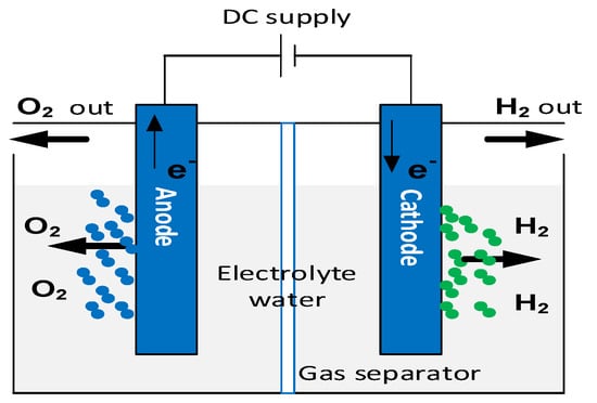
The electrochemical dissociation of water using renewable energies allows the production of green hydrogen and oxygen. This hydrogen production process is sustainable thanks to the use of the water electrolysis cell, as shown in Figure 1. An electrolyzer consists of two electrodes (anode and cathode) separated by an electrolyte, which may be solid or liquid [1].

Figure 1. Principle of water electrolysis [2].
There are three essential water electrolyzer technologies, two commercially accessible at both laboratory and industrial scales. These technologies are the alkaline electrolyzer (AEL), proton exchange membrane electrolyzer (PEMEL), and solid-oxide electrolyzer (SOEL) [3].


1.2. Fuel Cell Technologies
A fuel cell (FC) is an electrochemical conversion device that converts the chemical energy of a fuel (hydrogen) into electrical energy, without producing gas emissions (advantageous for the energy transition), noise, or vibrations, making it an ideal component for many applications [4]. The first functional FC dates back to the 1800s, thanks to the work of Sir William Grove. He duplicated the reverse process of electrolysis by combining hydrogen (H2) and oxygen (O2) to produce electricity through his experimental demonstration of water electrolysis [5]. It was not until 1959, when this field of study advanced, that the Englishman Francis Thomas Bacom presented the first completely functional FC [6][7].
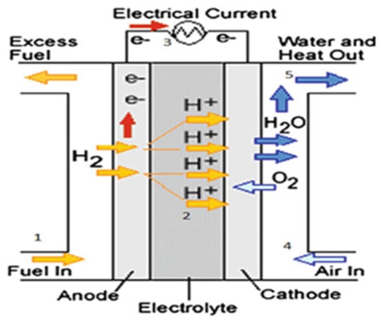
Nowadays, fuel cells are fully commercialized and have found applications in several fields, including transport, stationary, portable, energy cogeneration, and electric power generation, with modules ranging from a few kWs to several MWs. Among the different FC technologies, only six are used explicitly for electricity generation. These include proton exchange membrane fuel cells (PEMFCs), solid-oxide fuel cells (SOFCs), alkaline fuel cells (AFCs), direct methanol fuel cells (DMFCs), phosphoric acid fuel cells (PAFCs), and molten carbonate fuel cells (MCFCs) [8]. An FC consists of an electrolyte, an anode, a cathode, and an external circuit, as illustrated in Figure 2.

Figure 2. Basic diagram of a fuel cell [8].
Usually, hydrogen is delivered to the anode, where it oxidizes to form a proton and an electron. Protons pass through the electrolyte to the cathode, while electrons move along the external circuit, producing electricity. At the cathode, oxygen from the air is reduced to oxide, which reacts with protons and electrons to create water and heat. The tank receives a recirculation of any extra hydrogen that is not used up during the process [8][9]. The following equations depict the reactions at the anode (1) and cathode (2), respectively, at the negative electrode (hydrogen) and the positive electrode (air oxygen), as well as the total reaction (3) [9]:
The operating temperature (low, medium, and high) of the FC, the type of electrolyte used, the degree of purity, and the kind of fuel utilized as an energy carrier, are a few of the ways in which they differ from one another [10].
2. Hydrogen Storage Units in Hydrogen Production Systems
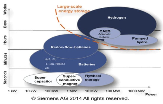
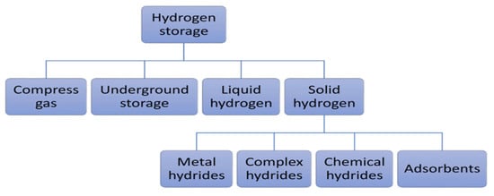
Figure 3 illustrates different energy storage technologies. It can be observed that energy storage technologies such as super-capacitors or flywheels are used to store a limited amount of power quickly and deliver it quickly. In contrast, energy storage technologies such as compressed air energy storage (CAES), pumping hydroelectric energy storage (PHES), or hydrogen storage are used on a large scale [11]. Developing large-scale hydrogen storage technologies will play an essential role in the energy transition. Different hydrogen storage technologies include high-pressure compressed gas, cryogenic liquid at very low temperatures, and solid-state and underground storage [2][12][13]. Figure 4 summarizes the other hydrogen storage technologies. The choice of a specific technology depends on factors such as the volume of storable hydrogen, duration, discharge rate, location, and cost.

Figure 3. Overview of technologies and their typical power and capacity ranges.

Figure 4. Hydrogen storage technologies [2].
2.1. Compressed-Gas Hydrogen Storage
The most common method of storing hydrogen directly is to store it in gaseous form at high pressure to reduce storage volume, since storage capacity is proportional to volume. Due to its very low density of approximately 0.089 kg/m3, hydrogen needs to be stored at high pressures. Currently, pressures of 25–35 MPa are used for storage (for fuel cell applications) and transport, and they can reach 70 MPa [14][15]. However, as pressure increases, this hydrogen compression process consumes excessive energy, leading to an increase in overall system cost [16]. This storage technology has limitations, including storage capacity being limited by the weight of the tanks and the high price of materials used for their design. These tanks require materials with specific properties, such as high thermal conductivity, and a structural design that can handle the increased internal temperature, to mitigate accelerated aging [2][14].
2.2. Underground Hydrogen Storage
Underground hydrogen storage stands out from the others because of the considerable volume of gas stored, the moderate or extended storage time, and the high capital investment required to build underground storage facilities [17]. There are various solutions for storing hydrogen underground: aquifers, natural gas, oil deposits (preferably already depleted), and salt caverns. These enable large-scale, medium- to long-term hydrogen storage [2][17][18]. However, the first two solutions may impact gas compositions because hydrogen can enter spaces that still contain many residual hydrocarbons, which is not beneficial for fuel cells for reconversion, as the discharged hydrogen may have unpredictable compositions. Salt caverns have attracted a great deal of interest compared with the other two, as they have incredibly high wall tightness, high operating pressures (maximum: 200 bar) at depths of up to 2000 m, geometric volumes of 500,000 m3 or more, a small footprint, low specific investment costs per MWh of storage, and low dependence on geological conditions [11][17][18][19]. Typical design parameters for a cavern with a depth of 1000 m include a volume of 500,000 m3 and a pressure ranging from 60 to 180 bar, representing a storage capacity equivalent to 80 GWh of electrical energy. One limitation to the expansion of this technology is that it is concentrated in areas or regions with significant salt deposits, which are not uniformly distributed [2][17].
2.3. Liquid Hydrogen Storage
In its liquid form, hydrogen has a much higher density, considerably increasing its volumetric energy density. The density of liquid hydrogen reaches around 71 g/L at −253 °C, where its energy density is equal to 8 MJ/L·H2 [12][14]. Hydrogen is liquefied at −253 °C (the boiling point of hydrogen) to be stored at low pressure in liquid form in tanks; its size is reduced due to its higher density, which is 1.5 to 2 times greater than that of compressed hydrogen at high pressure. Liquefied hydrogen’s global installed storage capacity is approximately 355 tons per day (tpd). Furthermore, today’s largest liquefaction plant has a capacity of 34 tpd. However, this hydrogen liquefaction process is very energy-intensive, requiring around 30 to 40% of the stored gas energy to be invested in the process, resulting in a considerable increase in costs. The problem of vaporization of escaping hydrogen is estimated at a rate of 1.5 to 3% per day, and the volume and weight of the tanks are also significant drawbacks of this system.
2.4. Solid Hydrogen Storage
Storing hydrogen in solid form solves the problems encountered in storing hydrogen in liquid form (evaporation and energy requirements) and gaseous form at high pressure (storage capacity due to tank weight, cost of materials, and energy requirements). Hydrogen can be combined physically or chemically with certain solid materials to store it in a solid state by absorption or adsorption [2][14][20]. Absorption allows hydrogen to be stored directly in the mass of the material to form hydrides (metallic, complex, and chemical hydrides). Metal hydrides (Ni, Li, Na, Mg, B, Al, etc.), compared with complex hydrides (NaAlH4, NaBH4, LiAlH4, LiBH4, Mg(AlH4)2, LaNi5H6, NH3BH3, NH3BH3, etc.) and chemical hydrides (LiH, NaH, MgH2, etc.), have attracted considerable interest, due to their excellent hydrogen storage capacities, including a high degree of safety, reversibility of hydrogenation/dehydrogenation, volumetric energy densities of hydrogen (about three times higher than liquid or gaseous storage), low-pressure equipment, and low energy requirements for stationary applications [11][20][21].
Physical adsorption, also known as physisorption, enables hydrogen to be stored by adsorption, by exploiting the Van Der Waals bonds between molecular hydrogen and a material with a large specific surface area. The materials most commonly used for hydrogen storage by adsorption are porous carbon-based materials, metal-organic structures, porous polymeric materials, and zeolites [2][12][21]. Despite their reversibility and rapid kinetics, these materials have a low hydrogen storage capacity under ambient conditions, requiring extremely low temperatures for high storage capacity. This constraint significantly limits the practical use of these materials in various applications. The low hydrogen storage capacity through adsorption hinders its commercialization [2][22].
For large-scale hydrogen storage, various storage technologies have been employed, including hydrogen compression and liquefaction. However, these methods have limitations in terms of storage volume and safety concerns, due to the highly flammable nature of hydrogen gas. To address these issues, underground hydrogen storage is a viable option as it offers high storage volume and is well-suited for large-scale hydrogen storage. Another interesting option is solid-state hydrogen storage, which directly stores hydrogen in chemical or physical form within solid materials that can absorb and release hydrogen reversibly. This technology has several advantages, such as high storage capacity, improved safety, and reduced tank weight, which can help solve the storage volume problems associated with traditional storage methods.
3. Different Projects Realized or Currently Underway on Large-Scale Hydrogen Production
The GrInHy project aims to supply green hydrogen by electrolysis using renewable electricity and to provide grid management services as a reversible generator at the Salzgitter Flachstahl GmbH (Salzgitter, Germany) steelworks. A reversible solid-oxide electrolyzer (RSOEL) was scaled up with 150 KWel electrolysis power and 30 KWel output power in reversible mode (FC operation with hydrogen), respectively, using 25 KWel with natural gas. After 5000 h of operation, the efficiency targeted by the project was 80% LHV in electrolyzer mode, which achieved 78% LHV at a flow rate of 40 Nm3/h. In the fuel cell mode fueled by natural gas, the prototype supplied electricity to the grid with an efficiency of 50% LHV. The system also showed a degradation rate of less than 1%/1000 h, which made it possible to predict its long-term functionality. The project started on 1 March 2016 and was completed on 28 February 2019 for EUR 4,498,150 [23].
The ROBINSON project aims to decarbonize industrialized islands by developing an integrated, intelligent, and cost-effective energy system that combines thermal, electrical, and gas networks to optimize the use of local RESs. Through the development of a smart, modular, and optimized energy management system (EMS), the project will integrate existing and newly developed technologies, such as a micro-gas turbine for combined heat and power generation, an anaerobic digester assisted by bio-electrochemical systems for converting liquid waste into bio-methane, an innovative mobile wind turbine, a gasifier for recycling biological waste, and hydrogen-related technologies (electrolyzer and storage system). The studies took place in Eigerøy, with a total duration of 48 months starting in 2020, and the European Union funds the budget of EUR 8.37 million. This integrated system will ensure a reliable and cost-effective energy supply while contributing to the decarbonization of European islands by helping to reduce CO2 emissions [24][25].
The Jupiter 1000 project is France’s first power-to-gas project on the natural gas transmission network. Located in Fos-sur-Mer, this project ensures the production of green hydrogen through 500 W PEMELs and AEL electrolyzers, both coupled with RES. The capture of CO2 on the chimneys of a nearby industrial plant also enables, after a methanation process, the production of SNG (substitute natural gas) of renewable origin, which can be mixed with hydrogen and then injected into the natural gas transport network. The project officially began in 2016 and ended in 2019, with an investment cost of EUR 30.8 million partially funded by the FEDER (European Regional Development Fund), the PACA region, and funds from the ADEME (French Environment and Energy Management Agency) Future Investments Program. The plant is designed to produce up to 25 Nm3/h of synthetic methane or 200 Nm3/h of hydrogen, with an average production of 5 GWh over three years [24][26].
References
- Guo, Y.; Li, G.; Zhou, J.; Liu, Y. Comparison between Hydrogen Production by Alkaline Water Electrolysis and Hydrogen Production by PEM Electrolysis. IOP Conf. Ser. Earth Environ. Sci. 2019, 371, 42022.
- Yue, M.; Lambert, H.; Pahon, E.; Roche, R.; Jemei, S.; Hissel, D. Hydrogen Energy Systems: A Critical Review of Technologies, Applications, Trends and Challenges. Renew. Sustain. Energy Rev. 2021, 146, 111180.
- Rashid, M.D.; Al Mesfer, M.K.; Naseem, H.; Danish, M. Hydrogen Production by Water Electrolysis: A Review of Alkaline Water Electrolysis, PEM Water Electrolysis and High Temperature Water Electrolysis. Int. J. Eng. Adv. Technol. 2015, 4, 80–93.
- Soo, L.T.; Loh, K.S.; Mohamad, A.B.; Daud, W.R.W.; Wong, W.Y. An Overview of the Electrochemical Performance of Modified Graphene Used as an Electrocatalyst and as a Catalyst Support in Fuel Cells. Appl. Catal. A Gen. 2015, 497, 198–210.
- Li, P.; Qiu, D.; Peng, L.; Lai, X. KW-Grade Unitized Regenerative Fuel Cell Stack Design for High Round-Trip Efficiencies. Energy Convers. Manag. 2022, 270, 116277.
- Schalenbach, M.; Tjarks, G.; Carmo, M.; Lueke, W.; Mueller, M.; Stolten, D. Acidic or Alkaline? Towards a New Perspective on the Efficiency of Water Electrolysis. J. Electrochem. Soc. 2016, 163, F3197.
- Sharaf, O.Z.; Orhan, M.F. An Overview of Fuel Cell Technology: Fundamentals and Applications. Renew. Sustain. Energy Rev. 2014, 32, 810–853.
- Akinyele, D.; Olabode, E.; Amole, A. Review of Fuel Cell Technologies and Applications for Sustainable Microgrid Systems. Inventions 2020, 5, 42.
- Ali, D.M.; Salman, S.K. A Comprehensive Review of the Fuel Cells Technology and Hydrogen Economy. In Proceedings of the 41st International Universities Power Engineering Conference, Newcastle upon Tyne, UK, 6–8 September 2006; Volume 1, pp. 98–102.
- Behera, P.R.; Dash, R.; Ali, S.M.; Mohapatra, K.K. A Review on Fuel Cell and Its Applications. Int. J. Res. Eng. Technol. 2014, 3, 562–565.
- Wolf, E. Large-Scale Hydrogen Energy Storage. In Electrochemical Energy Storage for Renewable Sources and Grid Balancing; Elsevier: Amsterdam, The Netherlands, 2015; pp. 129–142.
- Andersson, J.; Grönkvist, S. Large-Scale Storage of Hydrogen. Int. J. Hydrogen Energy 2019, 44, 11901–11919.
- Agyekum, E.B.; Nutakor, C.; Agwa, A.M.; Kamel, S. A Critical Review of Renewable Hydrogen Production Methods: Factors Affecting Their Scale-up and Its Role in Future Energy Generation. Membranes 2022, 12, 173.
- Wan, L.; Zhang, W.; Xu, Z. Overview of Key Technologies and Applications of Hydrogen Energy Storage in Integrated Energy Systems. In Proceedings of the 2020 12th IEEE PES Asia-Pacific Power and Energy Engineering Conference (APPEEC), Nanjing, China, 20–23 September 2020; pp. 1–5.
- Dewangan, S.K.; Mohan, M.; Kumar, V.; Sharma, A.; Ahn, B. A Comprehensive Review of the Prospects for Future Hydrogen Storage in Materials-application and Outstanding Issues. Int. J. Energy Res. 2022, 46, 16150–16177.
- Elberry, A.M.; Thakur, J.; Santasalo-Aarnio, A.; Larmi, M. Large-Scale Compressed Hydrogen Storage as Part of Renewable Electricity Storage Systems. Int. J. Hydrogen Energy 2021, 46, 15671–15690.
- Tarkowski, R.; Uliasz-Misiak, B. Towards Underground Hydrogen Storage: A Review of Barriers. Renew. Sustain. Energy Rev. 2022, 162, 112451.
- Tarkowski, R. Underground Hydrogen Storage: Characteristics and Prospects. Renew. Sustain. Energy Rev. 2019, 105, 86–94.
- Takach, M.; Sarajlić, M.; Peters, D.; Kroener, M.; Schuldt, F.; von Maydell, K. Review of Hydrogen Production Techniques from Water Using Renewable Energy Sources and Its Storage in Salt Caverns. Energies 2022, 15, 1415.
- Prabhukhot Prachi, R.; Wagh Mahesh, M.; Gangal Aneesh, C. A Review on Solid State Hydrogen Storage Material. Adv. Energy Power 2016, 4, 11–22.
- Ratnakar, R.R.; Gupta, N.; Zhang, K.; van Doorne, C.; Fesmire, J.; Dindoruk, B.; Balakotaiah, V. Hydrogen Supply Chain and Challenges in Large-Scale LH2 Storage and Transportation. Int. J. Hydrogen Energy 2021, 46, 24149–24168.
- Abe, J.O.; Popoola, A.P.I.; Ajenifuja, E.; Popoola, O.M. Hydrogen Energy, Economy and Storage: Review and Recommendation. Int. J. Hydrogen Energy 2019, 44, 15072–15086.
- Schwarze, K.; Posdziech, O.; Mermelstein, J.; Kroop, S. Operational Results of an 150/30 KW RSOC System in an Industrial Environment. Fuel Cells 2019, 19, 374–380.
- Borge-Diez, D.; Rosales-Asensio, E.; Açıkkalp, E.; Alonso-Martínez, D. Analysis of Power to Gas Technologies for Energy Intensive Industries in European Union. Energies 2023, 16, 538.
- Madi, H.; Lytvynenko, D.; Schildhauer, T.; Jansohn, P. Decarbonisation of Geographical Islands and the Feasibility of Green Hydrogen Production Using Excess Electricity. Energies 2023, 16, 4094.
- Boulanger, V.; Descamps, O.; Rap, C. Hydrogen-Hydrogen Goes Green: Hydrogen, Imminent Launch; Jupiter 1000: The Gas and Electricity Worlds Learn to Communicate; NortH2, a Green Hydrogen Giga-Project. J. Energies Renouvelables 2020, 51, 30–39.
More
Information
Subjects:
Engineering, Environmental
Contributors
MDPI registered users' name will be linked to their SciProfiles pages. To register with us, please refer to https://encyclopedia.pub/register
:
View Times:
687
Revisions:
2 times
(View History)
Update Date:
26 Mar 2024
Notice
You are not a member of the advisory board for this topic. If you want to update advisory board member profile, please contact office@encyclopedia.pub.
OK
Confirm
Only members of the Encyclopedia advisory board for this topic are allowed to note entries. Would you like to become an advisory board member of the Encyclopedia?
Yes
No
${ textCharacter }/${ maxCharacter }
Submit
Cancel
Back
Comments
${ item }
|
More
No more~
There is no comment~
${ textCharacter }/${ maxCharacter }
Submit
Cancel
${ selectedItem.replyTextCharacter }/${ selectedItem.replyMaxCharacter }
Submit
Cancel
Confirm
Are you sure to Delete?
Yes
No


