1. Symmetric Friction Connections (SFC)
1.1. Rotational Slotted Bolted Connection
One of the pioneer symmetric friction devices applied to BCCs was reported in
[1][2] (
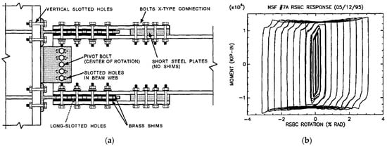
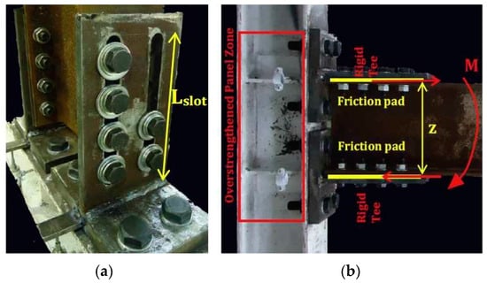
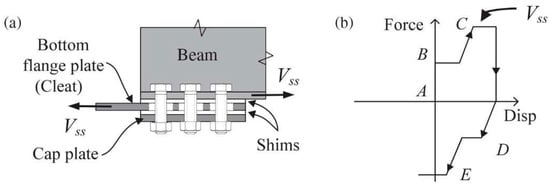
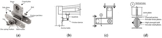
Figure 1a) by Grigorian and Popov, and Yang and Popov, respectively. The system comprises T-stubs, each of these bolted to the beam flanges and covered by a cap plate. A friction shim is inserted at each interface of the T-stub-cap plate and T-stub-beam flange, in order to form two linear friction devices. On the column flange, a beam web is bolted via vertical steel angles, in which the central bolt acts as the fixed center of rotation, while the other bolts are inserted through slotted holes.
Figure 1. (
a) Symmetric connections with two or more friction shims per side: rotational slotted bolted connection (RSBC); (
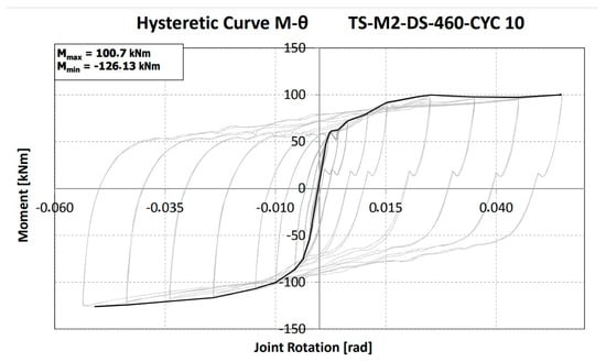
b) RSBC experimental moment–rotation curve (taken from
[1]).
One of the advantages of this solution is that, having a properly defined center of rotation, the kinematic of the connection is readily predictable. However, the position of the center of rotation causes a sensible gap opening during rotation between the column flange and top beam flange, leading to potential damage to the slab. In addition, particular attention should be given to the design of the bolt representing the center of rotation, named the pivot bolt, as well as the plates connected by it.
As a matter of fact, the first of the two specimens tested by
[1] showed that no element constituting the connection was damaged at the end of the test, except for the pivot bolt, whose shank was bent by shear. In addition, reversed cyclic action enlarged the hole on the beam web through which the pivot bolt was inserted. For this reason, for the second specimen a larger pivot bolt was adopted, and the beam web was reinforced.
The experimental tests employed brass as the friction shim material. The results showed that, although the brass provided exceptionally stable cyclic behavior, as shown in Figure 1b, its friction coefficient was quite low and required building a connection with many friction surfaces and bolts to obtain proper moment strength. Furthermore, the moment of the connection during the sliding phase showed a slight hardening behavior.
This can be explained by the fact that, once the connection started to rotate, the T-stubs were bent, and the bending moment acting on them contributed to increase the moment of the whole connection. With regard to the shape of the corners of the hysteresis loops, this is due to slippage of the brass pads during load reversal, caused by the clearance hole.
Despite the several flaws affecting the proposed solution, it can be stated that the tested connections behaved outstandingly well. It is worth remembering that this solution was a pioneering one and the application of such friction connections to structural engineering was at the very beginning.
1.2. Removable Friction Dampers for Low-Damage Connections
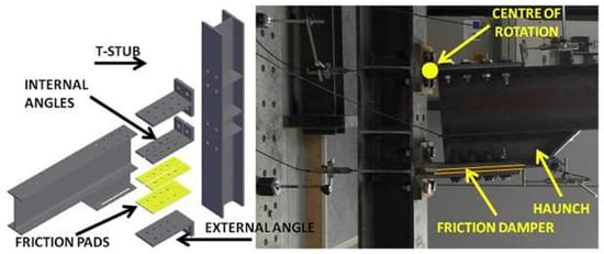
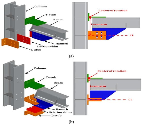
The research group of the University of Salerno (Italy), in collaboration with the Federico II University of Naples, Italy, has proposed two other solutions. In the first one, the dissipative friction plates slide in the horizontal direction (
Figure 2), while in the other the sliding is in the vertical direction
[3] (
Figure 3). These solutions aim at solving three main flaws of a previously proposed asymmetric solution
[4], i.e., the lack of a center of rotation, the asymmetric configuration of the friction connections, and the relatively small moment capacity, which is due to a combination of the small internal lever arm of the connection and the small number of friction surfaces for each side (i.e., equal to 1).
Figure 2. Symmetric connections with additional steel element(s) and two or more friction shims arranged horizontally (taken from
[5]).
Figure 3. Symmetric connections with additional steel element(s) and two or more friction shims arranged vertically (taken from
[3]).
In both of these solutions, an additional steel element (I-shaped for a horizontal dissipative device, while it is T-shaped in the case of a vertical one) is bolted to the bottom beam flange in order to increase the internal lever arm of the joint and reduce the forces acting on the panel zone.
Another advantage provided by the additional steel element is that it makes it possible to double the surfaces on which friction forces are generated, considerably improving the performance of the connections. A T-stub is bolted to the column and upper part of the beam to establish a connection. In both solutions, the center of rotation is expected to form at the base section of the upper T-stub. The solution with the horizontal dissipative device is made by using three steel angles which are bolted to the I-shaped section, having one friction pad for each steel angle (Figure 2).
The solution with the vertical dissipative device needs two steel angles, requiring two groups of slotted holes, one vertically oriented on the steel angles, and the other one horizontally oriented on the T-shaped profile as shown in Figure 3, so the bolts are allowed to move in both directions. By contrast, in the solution with a horizontal dissipative device, the displacement component in the vertical direction is absorbed by deformation of the lower steel angles. It is different from the horizontal system, in which low damage to the lower steel angles is admitted; the vertical one prevents any damage of the friction connection. However, bolts belonging to the friction device are subjected to plastic deformations due to the contact between the horizontal slotted holes of the T-shaped profile and the bolt shanks. The fact is that these bolts have to be dragged up and down by the T-shaped profile, in the vertical direction, to allow connection rotation.
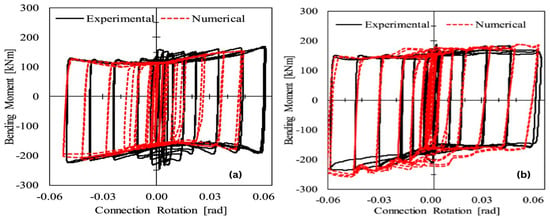
With regard to mechanical behavior, the horizontal system shows an increment of the moment capacity, in both directions, due to the progressive plasticization of the lower steel angles (Figure 4a). As for the vertical system, the contact between bolt shanks and horizontal slotted holes causes an increment of the moment capacity, which depends on the amount of bolt shanks dragged by the T-shaped profile. For this reason, the backbone curve of the moment–rotation behavior shows a sawtooth-like shape (Figure 4b).
Figure 4. (
a) Moment–rotation behavior of the horizontal system; (
b) the vertical system (taken from
[3]).
The moment capacity increment due to these phenomena has to be properly taken into account when designing the members connected to the friction connection with the aim of avoiding damage formation.
Therefore, it is worth outlining the design procedure of the above connection. The force
Fd for which the connection starts to slide can be calculated as follows:
in which
Md is the design bending moment and
z is the lever arm, being the distance between the center of rotation and the axis of sliding. According to
[6], the sliding force
Fd can be obtained as
where
Ks = a coefficient that depends on the shape of the slotted hole,
nb = the number of bolts,
ns = the number of surfaces in contact,
µ = the friction coefficient,
γM3 = a safety factor, and
Fpc = the preloading force of each bolt.
Fpc can be assessed as follows:
where
fub = the ultimate strength of steel,
Ares = the resisting area of the bolt, and
ts = a parameter ranging between 0.3 and 0.6, introduced to keep the bolt within the elastic range and thus limit preload losses due to creep phenomena
[7][8][9].
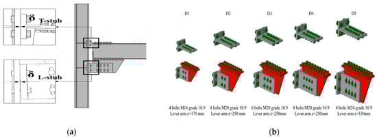
Tartaglia et al.
[10] conducted a parametric study by using the finite-element simulation and modeling of a steel beam-to-column joint. To this aim, a set of five friction dampers based on the steel profiles used in Eurocode-compliant multi-story moment-resisting frames were used shown in
Figure 5. Experimental tests were performed in a previous study
[3], and the FEM models were calibrated against those tested before.
Figure 5. (
a) L-stub configuration; (
b) five symmetric friction dampers with their configuration (taken from
[10]).
The aim of this research was to extend the findings of the experimental results, investigating the behavior of different damping connections. The surface interaction of the plate to plate and bolt to plate were modeled using the tangential and normal behavior. For normal behavior, “Hard Contact” is taken, while tangential behavior is modeled differently for friction pads to steel and steel to steel interfaces.
For friction dampers, the dynamic friction coefficient is taken as 0.59
[11] and for steel-to-steel surfaces it is taken as 0.3. Pre-tensioning of the bolts was performed in order to apply bolt preload according to the recommendation of EN1993:1–8
[6]. The column was allowed to deform along its own axis by pinning it at the bottom end and by allowing all flexural rotations, as well as vertical displacements at the upper end. The beam tip was simply pinned while it was restrained by means of lateral-torsional buckling in accordance with
[6]. Both cyclic and monotonic displacement histories were applied at the beam tip in accordance with
[12].
The following results can be derived from the simulations.
-
The rotational capacity and ductility of the friction connection is dependent on some of the factors like the lever arm of joint, the length of the slotted holes in the rib, and the gap between the beam’s tip and column flange, which restrains contact between the connected members under hogging flexure, while it permits plastic hinge formation at the base of the T-stub web;
-
It was found that the effectiveness of friction joints is not dependent on the size of the connected members because the hysteretic and monotonic response of all joints was almost the same;
-
The friction dampers and connections give a rotation capacity of about 0.07 rad, which fulfills the minimum rotation capacity criteria given in
[13] for dissipative joints;
-
The flexural response of the joints having the proposed dampers is not symmetric, and for the chord rotation of 0.04 rad the hogging resistance is about 25% greater than the sagging resistance. This is mainly due to the higher deformability of L-stubs under the sagging moment, which causes a higher loss of bolt preload as compared to the loss when the L-stubs are in compression.
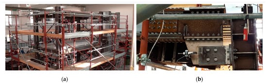
In order to find the seismic response of low-damage/FREEDAM joints, the authors of
[14] tested a large scale two-story building mock-up having two equal frames equipped with low-damage FREEDAM joints having friction dampers as shown in
Figure 6.
Figure 6. (
a) Tested moment resisting frame equipped with a FREEDAM joint; (
b) configuration of the tested FREEDAM joint (taken from
[14]).
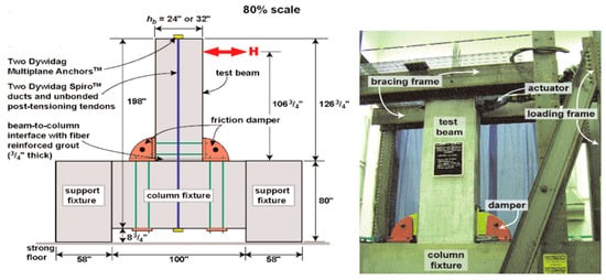
To simulate seismic event effects, a sequence of five accelerograms was applied by pseudo-dynamic testing. The geometrical details of the tested FREEDAM joint are shown in Figure 7.
Figure 7. Geometrical configuration and details of a low-damage design (FREEDAM) joint (taken from
[14]).
The experimental results confirmed that low-yielding friction joints provide enough energy dissipation and rotation supply without any damage. These experimental results were verified by a numerical method.
It was also found that the connection did not suffer any damage but there was minor yielding, as in the results provided by
[15] for beam-to-column joints’ sub-assemblages. At the end of tests, the friction pads needed to be repaired because of friction and energy dissipation. There was a slight degradation of the connection’s flexural resistance during the experimental campaign, which proves that friction pads can resist the seismic event, but minor repair may still be needed.
1.3. Self-Centering Friction Connection for PRC MRFs
As underlined in the introduction, in order to obtain devices that guarantee full functionality of the structure after an earthquake, a significant characteristic of the device is recentering capacity. In the literature, various devices are designed according to the methods that characterize the recentering behavior of the device proposed in
[16][17][18]. The device shown in
Figure 8 was developed for PRC structures.
Figure 8. Symmetric connections with two or more friction shims per side for PRC structures (taken from
[16]).
The connection between the beam and column is established by using two bolts inserted through curved slotted holes. Each dissipative device is constituted by four friction shims (Figure 9).
Figure 9. Friction device layout (taken from
[16]).
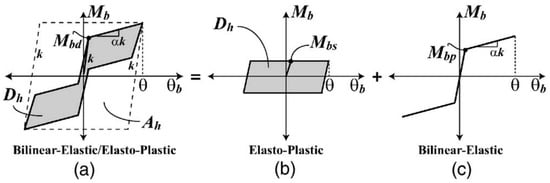
The beam and column are connected with one or more unbounded post-tensioned tendons, which are placed at the mid-height of the beam cross-section, providing self-centering behavior to the connection. Figure 10 shows the theoretical moment–rotation curve of the self-centering connection, as well as the contribution provided by friction devices and post-tensioned tendons. The latter are characterized by bilinear-elastic behavior, in which the moment value Mbp is tuned by means of the preload force acting on the tendons, while second branch stiffness is ruled by the axial stiffness of the tendons. It should be noted that the theoretical contribution made by post-tensioned tendons does not dissipate energy, with these behaving elastically.
Figure 10. Theoretical moment−rotation curves of (
a) a self-centering friction connection; (
b) friction dampers only; (
c) post-tensioned tendons only (
c) (taken from
[17]).
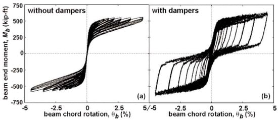
Yet this is not fully confirmed by experimental tests, as can be seen in Figure 11, which shows two moment–rotation curves of a subassembly endowed with post-tensioned tendons and including or not including friction dampers. In both cases, the greater the rotation achieved by the connection, the lower the moment value for which the gap at the beam-to-column interface opens (i.e., without dampers it equals Mbp, Figure 11a; with dampers it equals Mbd, Figure 11b).
Figure 11. Experimental moment−rotation curve of the beam-to-column joint endowed with (
a) post-tensioned tendon only; (
b) and coupled with friction dampers (taken from
[16]).
This phenomenon was due to concrete cracking and crushing at the beam and column interface. As a matter of fact, this contact is required to transfer the shear force between the beam and column: otherwise, in the presence of friction connections, these would withstand this force and their functioning would be hampered.
Moreover, progressive damage to concrete also leads to hysteretic cycles with a small amplitude in the case of a subassembly without dampers. On a final note, the results provided by post-tensioned tendons are promising in terms of dissipative and self-centering capacities. However, it has to be stressed that this structural typology requires tensioning the tendons in the construction site once the PRC members are put in place, limiting its use to large constructions only.
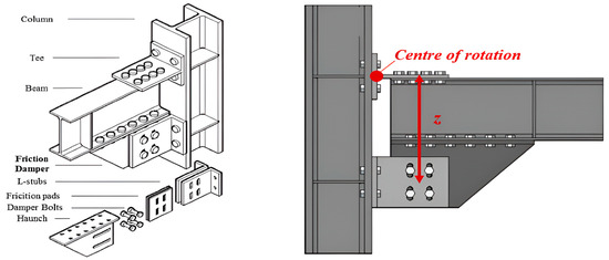
1.4. Symmetric Vertical Friction Connection for RC Columns and Hybrid Beams
The friction-based BCC proposed in
[19][20][21][22] is the only one in the literature designed for connecting RC columns cast in situ connected with HSTCBs. The need to design such a device was highlighted by experimental tests conducted on traditional connections between RC columns and HSTCBs, which highlighted the loss of stiffness caused by the cracking of the joint panel in connections with beams characterized by a high percentage of longitudinal reinforcement
[23][24].
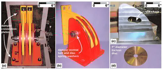
The device was designed to connect an HSCTB having dimensions of 300 × 250 mm
2 and longitudinal rebars of 4ϕ24 (top) + 2ϕ24 (bottom), taking advantage of the steel plate on the bottom side of the beam, which acts as a mold in the casting phase and as a reinforcing element at the serviceability limit states (SLS) and ultimate limit states (ULS). The transverse reinforcement of the beam was ϕ8/6 cm. A major issue in the design of the devices was the shear strength that had to be provided to the beam, which was calculated as 350 kN using the analytical model of
[25], which develops that proposed in
[26].
The device specimen is represented in
Figure 12b; the T-stub is made of an HEB300 profile, and the connection between the T-stub and HSTCB was made with eight M20 bolts Class 10.9, while the connection between the column and T-stub was made of four M24 bolts Class 10.9. The steel angles were coated with thermal sprayed aluminum and used as friction pads, as shown in
Figure 12c. Thermal sprayed aluminum was chosen as the friction material based on its excellent performance as tested by
[27]. The connection between the vertical central plate and thermal sprayed aluminum steel angles was established by five M20 bolts Class 10.9 and the thermal sprayed aluminum steel angles were connected with the column with four M24 bolts Class 10.9. In total, 500 kN of axial load was applied on the column to replicate the dead load effect.
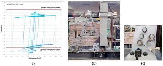
Figure 12. (
a) Force−displacement curve of HSTCB and column with a friction dissipative device (taken from
[27]); (
b) specimen endowed with friction device; (
c) friction device.
Displacement controlled tests were performed on HSTCBs at a distance of l = 1.31 m (from the center of rotation to the point of applied displacement). The displacement history was considered as suggested by ACI 374.2R-13 (2013)
[28]. Two cycles of five amplitudes of maximum displacement of ± 2 mm, ± 5 mm, ± 10 mm, ± 20 mm, and ± 40 mm were applied. Several tests were performed, with joint strength equal to 0.35, 0.5, 1, and 1.5 of the ultimate bending strength of the HSTCBs, equal to 105 kN-m. In
Figure 12a, the result of the test with the lower strength, namely 36.75 kN-m, is reported, where a torque was applied on the bolts to achieve a preload of 17 kN, and an expected sliding force equal to
Fsl = 29 kN. The results showed that the beam–column connection provides stable and wide hysteresis loops without any damage or cracking. There were different values of the sliding force in the case of the sagging moment and hogging moment due to a change in the lever arm. It was also found that the sliding force reduces during the test because of the wearing of the surface and loss of preload force due to the stick and slip phenomenon.
2. Asymmetric Friction Connections (AFC)
2.1. Dissipative Double Split Tee Connection
A solution named the dissipative double split tee connection (DDSTC)
[4] was developed at the University of Salerno, Italy. The connection is established by using two T-stubs, which are bolted to the beam flanges having slotted holes in order to permit the bolts to slide (
Figure 13). A friction shim is inserted between the beam flange and T-stub in order to provide energy dissipation capacity. The connection is designed in order to allow displacement of the vertical component due to the rotation by means of the deflection of T-stubs. The latter are supposed to undergo plastic deformations at the base section and then to be replaced after the seismic event. This configuration has a variable center of rotation, leading to potential significant damage to the slab.
Figure 13. Asymmetric connections with one friction shim per side: dissipative double split tee connection (DDSTC). (
a) Bottom view; (
b) side view (taken from
[4]).
The experimental tests showed remarkable performance characterized by adequate dissipative capacity and slight hardening behavior due to the bending moment acting on the T-stub flanges, as already seen in the RSBC (Figure 14). The solution simplifies the configuration of the RSBC by removing cap plates and pivot bolt.
Figure 14. DDSTC experimental moment–rotation curve (taken from
[4]).
The reduction in the number of surfaces on which friction forces are generated, which would lead to a lower moment capacity of the connection, is compensated by using friction shims having a higher friction coefficient. However, by doing so the friction connections become asymmetric and the bolts are subjected to a combined axial force-shear force-bending moment that might lead to plastic deformations of the bolt shanks, potentially causing decreasing clamping forces and a poor cyclic performance of the connection.
Latour et al.
[29] conducted an experimental campaign on asymmetric beam-to-column joints and derived an analytical model on the basis of the component method
[6]. The main aim of this research was to predict the cyclic behavior of partial-strength BCCs, which helps researchers to correctly analyze the nonlinear response of connections in seismic time-history analyses and to precisely predict the degradation of the sliding properties of friction connections.
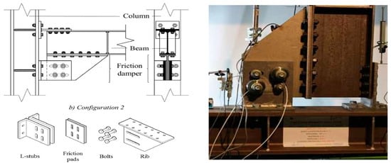
The tested beam-to-column joint is like a conventional double split tee connection. However, some modifications are made. In traditional double split tee connections, the bottom T-stub is used to connect the column with the lower flange; but here it is replaced with a friction device in order to have two different geometrical configurations, as shown in Figure 15.
Figure 15. (
a) Damper plane parallel to beam flange (Configuration 1); (
b) damper plane parallel to beam web (Configuration 2) (taken from
[29]).
In Configuration 1 (Figure 15a), the symmetrical friction pads are parallel to the beam flange. Here, the device consists of friction shims, 10.9 high-strength preloaded bolts, a couple of L-stubs, and a slotted stainless-steel haunch which allows sliding of the device. To help the transfer of bolt forces and clamp the friction shims and the haunch together, the L-stub is used to connect the assembly with a column flange.
In Configuration 2 (Figure 15b), there is a relative movement of L-stubs and rib plates in friction shims which produce sliding, so all of these elements have slotted holes.
The friction device consists of a stainless-steel plate (lower part of the haunch in Configuration 1 and rib plate in Configuration 2). One of the interesting things is that the damper performs the same way in both cases but a relative decrease or increase in the bolt preloading forces can occur for Configuration 1 due to the flexibility of the L-stubs and rigid beam rotation, while there is no such increase or decrease for Configuration 2 as there is no variation in bolt forces because it is independent of L-stub deformation.
The experimental analysis confirmed that the response of the Configuration 1 joint was asymmetric and caused fluctuations of the bolt preload. This is because of the different deformability of the L-stubs in compression and tension and also due to the non-uniform pressure distribution in the friction interface because of the incompatibility between the bending of L-stub and joint rotation in Configuration 1.
When the specimen is cruciform, the asymmetry disappears at the same time because at the same nodal point one of the connections is under a sagging bending moment while the other is in hogging. Thus, it can be deduced that locally the behavior of the friction joints is asymmetric while the overall response of the moment-resisting frame will be symmetrical for any direction of the seismic forces. This is due to the same number of connections in both bending (hogging and sagging).
The results also show that in Configuration 2, the friction joints are less prone to variation in the bolt forces, which show a less asymmetric response as compared to Configuration 1.
2.2. Two-Level Friction-Yielding System
Among the hybrid solutions mentioned previously, to address the requirements at both the damage limit state (DLS) and ultimate limit state (ULS), Asgari et al.
[30] proposed a beam–column node for steel structures made with a “two-stage” damper for BCCs by combining two separate control systems with different strengths and stiffnesses. The system includes one asymmetric friction and one yield damper on the top plate of the beam-to-column joint. In this control system, the frictional damper acts as the first member for dissipating the energy transmitted by an earthquake, and in the case of insufficient capacity, the yielding damper comes into action and dissipates the energy using plastic deformations. The cyclic behavior of these systems was subjected to a nonlinear analysis with ABAQUS 2017 software. Parametric FEM analyses investigate the effect of different values of the length-to-thickness ratio of the friction plate of the upper wing, the ratio between the areas of the plate to be yielded and the section of the beam with elastic behavior, and the force that activates plate sliding. Two specimens were subjected to laboratory tests. The results confirmed the absence of cracking or failure of the welds, or significant variation in the preload bolts, highlighting the effectiveness of the sizing of the proposed rigid connection. Finally, the effectiveness of the device in limiting damage to a steel portal subjected to seismic excitation at the foot, characterized by two different intensity levels, was verified through step integrations of the equation of motion in the nonlinear field by again employing the FEM code.
3. Asymmetric Connections with Cap Plate
Sliding Hinge Joint with Asymmetric Friction Connection
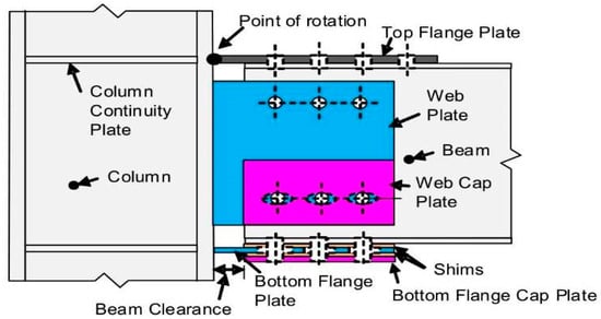
Among the most recent connections developed at the University of Auckland and University of Canterbury, an important role is played by the connection named the sliding hinge joint with asymmetric friction connection (SHJAFC) shown in
Figure 16 [31][32][33].
Figure 16. Asymmetric connections with one or more friction shims: sliding hinge joint (SHJ) (taken from
[31]).
The solution solves two main drawbacks affecting the RSBC, namely the center of rotation constituted by a pivot bolt, to which particular attention has to be paid during structural design to avoid any damage to the bolt itself and to the plates connected by it, and the gap opening between the top flange of the beam and the column flange, which could potentially lead to damage to the slab. In SHJAFC, the connection between the beam and column is established by using two horizontal steel plates welded to the flange of the column. The connection between the beam and these plates is established by bolts; the one above is a standard bolted friction connection, while in the one below these are inserted through the slotted holes in order to permit beam rotation.
Another friction shim is placed at the bottom connection by using a cap plate. A vertical plate is welded to the column flange and bolted to the beam web by means of two horizontal rows of bolts. The top one is a standard bolted connection, while the bottom one has horizontal slotted holes which permit beam rotation. Moreover, with the aim to increase the dissipative capacity of the connection, a cap plate is bolted to the outer side of the web plate. Between the cap plate and web plate, and between the web plate and the beam web, two friction shims are inserted.
The rotation of connection starts when the friction forces of the shims inserted between the bottom beam flange and bottom plate, beam web and web plate, are achieved. Increasing the rotation of the system, the total friction force doubles when the friction shims inserted between the bottom and web plates and the cap plates begin to slide (Figure 17).
Figure 17. (
a) Asymmetric friction connection (AFC); (
b) its moment–rotation curve (taken from
[31]).
During the design step of the SHJAFC, special attention must be paid to the serviceability limit state and to wind loads. As a matter of fact, due to the above-mentioned moment–rotation behavior, the connection could start to rotate when subjected to loads different from those caused by the design earthquake. Furthermore, the asymmetric arrangement of the friction device leads to bolts contemporarily subjected to moment, shear, and axial load, which, in early versions of this connection, caused plastic deformations of the bolt shanks. This phenomenon decreased clamping force leading to hysteretic cycles characterized by a progressive reduction in the sliding force. To solve this issue, bolts have to be kept within the elastic range and coupled with disc springs able to absorb the elongation undergone by bolt shanks
[34].
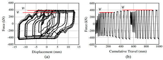
When an SHJAFC is endowed with friction pads having a much higher hardness than that of constructional steel, it provides wide and stable hysteretic cycles, with a slight progressive increase in sliding force (Figure 18). This phenomenon is due to the formation of asperities on the surfaces in contact.
Figure 18. (
a) Asymmetric friction connection force−displacement curve; and (
b) force−cumulative travel (
b) (taken from
[31]).
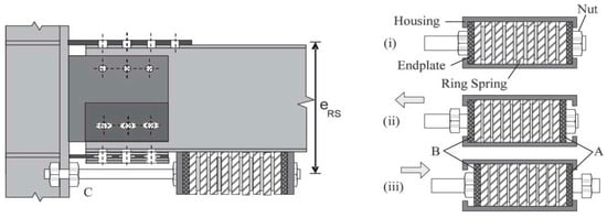
From the pioneering configurations developed at the end of the last century, during the last decade the sliding hinge joint (SHJ) has been further developed in order to be self-centering
[35][36]. This behavior is obtained by adding to the bottom beam flange a stack of preloaded ring springs inserted in a box-shaped case. A bar is inserted through the ring springs and is bolted to the column flange. The system is designed to deform the ring springs in compression only for both hogging and sagging moment (
Figure 19).
Figure 19. Self-centering sliding hinge joint (SCSHJ): (C) Steel rod establishing connection between ring springs and column; (A,B) end plates; (i) neutral position; (ii) in tension; and (iii) in compression (taken from
[36]).
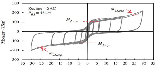
Experimental tests carried out on different combinations of moment strength provided by the AFC and the stack of disc springs pointed out that the higher the percentage of moment strength provided by the AFC on the whole moment strength of the connection, the lower the self-centering capacity of the connection itself.
For instance, Figure 20 shows the moment–rotation curve of a self-centering SHJAFC characterized by a percentage of moment capacity provided by preloaded ring springs PRS of 52.4%. It can be seen that, despite PRS being more than half of the whole moment capacity of the connection, significant residual drift was still obtained. Therefore, PRS should be increased by using a better performing and thus more expensive self-centering system. In addition, the connection behaved according to design requirements for rotation of up to 25 mrad.
Figure 20. SCSHJ experimental moment–rotation curve (taken from
[36]).
Above this value, the vertical component of the displacement due to the rotation was no longer negligible and the moment strength increased rapidly. This is due to the fact that the connection was not designed to accommodate large displacements in the vertical direction; thus, some damage could have been experienced by the connection. Moreover, in the case of seismic events leading to rotation well above 25 mrad, the increment in the moment strength of the connection could have led to the formation of a plastic hinge at the beam end or, worse, to damage to the column. For this reason, a real application of this connection should select an appropriate overstrength factor to design the members surrounding the connection to prevent any damage.
4. Rotational Friction Devices
The rotational friction devices shown in
Figure 21 were designed in
[37][38] to connect the braces and beam of BF, while the work in
[39] developed a dissipative connection. In the late 1980s
[40], a rotational friction devices was placed between two small link elements placed close to a BCC and orthogonally to the beam and column of a precast reinforced concrete industrial frame, in order to obtain a device.
Figure 21. (
a) Components of RFD
[38]; (
b–
d) energy dissipation device
[39]; (
b) local incorporation; (
c) front view; and (
d) section view detail.
Regarding the friction BCC of PRCs, most of the dissipative connections use post-tensioned tendons
[17][41], which can provide frame recentering capabilities but can be affected by loss of prestressed load for concrete, creep and shrinkage, and steel relaxation. To overcome this problem, one must avoid modification of the stiffness of the elements due to prestressing action and ensure that the resistance level of the connection can be easily adjusted. In
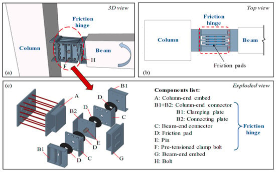
[42], the dry-connected rotational friction dissipative BCC for precast concrete (PC) frames based on the principles that characterize the operation of steel structure BCCs was proposed (
Figure 22) and tested. The device consists of friction pads (D), a pin (E), pre-tensioned tightening bolts (F), and connectors at the column and beam ends (B1, B2, and C). The friction hinge is connected to the embedded elements (A and G) of the PC beam and the column with bolts. The friction pads are compressed by the tightening bolts.
Figure 22. Configuration of a rotational friction dissipative BCC for precast concrete (PC) frames: (
a) 3-D view; (
b) top view; (
c) components list
[42].
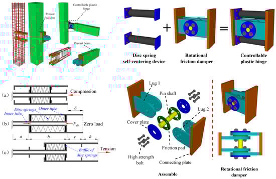
Recently, in Ma et al.
[43] the results of numerical analysis preparatory to the experimental verification of device capabilities were reported, aiming at verifying the performance of a PRC MRF using a prefabricated self-centering concrete beam-to-column joint. The joint was equipped with a controllable plastic hinge consisting of a rotational friction damper able to withstand a bending moment and provide dissipative behavior, a pin shaft to carry the shear force, and disc spring self-centering devices as shown in
Figure 23. A numerical analysis performed by a macromodel implemented in Opensees (
https://opensees.berkeley.edu/ (accessed on 6 February 2024))
[44] proved the efficiency and energy dissipation capacity of the system. The device is characterized by a flag-shaped moment–rotation relationship, and the optimal value of the ratio α between the bending moment provided by the disc spring self-centering prestressing force 2
Fs0 and the bending moment required to activate the damper
Mf should be chosen in the range of 1.00–1.30, while the overstrength ratio between the ultimate moment of the beam and the activation moment of the damper should be chosen in the range of 1.3–1.4. It has to be emphasized that the aforementioned values must be confirmed by experimental testing.
Figure 23. Self-centering prefabricated RC beam-to-column joint: (
a) under compression; (
b) neutral position; (
c) in tension
[43].
In
[45], a rotational friction connection for steel MRFs able to control the load-displacement relation at different performance levels is proposed and tested. The connection is characterized by a rotational hinge with a fixed rotation center at the level of the beam axis, obtained by two π-shaped plates with a central pin shaft, and radial slotted holes, and two steel plate linear friction dampers at the top and bottom flanges of the beam. The connection is designed in order to be easily recovered if, in the presence of seismic action, damage to the surface of the steel plate damper or reduction in the bolt preload is detected, as specific tests aimed at simulating a maintenance intervention on the device after a major seismic event have demonstrated.
 +1 credit