Your browser does not fully support modern features. Please upgrade for a smoother experience.
Submitted Successfully!
 +1 credit
Thank you for your contribution! You can also upload a video entry or images related to this topic.
For video creation, please contact our Academic Video Service.
| Version | Summary | Created by | Modification | Content Size | Created at | Operation |
|---|---|---|---|---|---|---|
| 1 | Hussain Al Mahdi | -- | 5395 | 2024-03-11 10:49:26 | | | |
| 2 | Fanny Huang | -10 word(s) | 5385 | 2024-03-12 04:11:30 | | |
Video Upload Options
We provide professional Academic Video Service to translate complex research into visually appealing presentations. Would you like to try it?
Cite
If you have any further questions, please contact Encyclopedia Editorial Office.
Al Mahdi, H.; Leahy, P.G.; Alghoul, M.; Morrison, A.P. Failures of the Photovoltaic Module Components. Encyclopedia. Available online: https://encyclopedia.pub/entry/56103 (accessed on 25 June 2026).
Al Mahdi H, Leahy PG, Alghoul M, Morrison AP. Failures of the Photovoltaic Module Components. Encyclopedia. Available at: https://encyclopedia.pub/entry/56103. Accessed June 25, 2026.
Al Mahdi, Hussain, Paul G. Leahy, Mohammad Alghoul, Alan P. Morrison. "Failures of the Photovoltaic Module Components" Encyclopedia, https://encyclopedia.pub/entry/56103 (accessed June 25, 2026).
Al Mahdi, H., Leahy, P.G., Alghoul, M., & Morrison, A.P. (2024, March 11). Failures of the Photovoltaic Module Components. In Encyclopedia. https://encyclopedia.pub/entry/56103
Al Mahdi, Hussain, et al. "Failures of the Photovoltaic Module Components." Encyclopedia. Web. 11 March, 2024.
Copy Citation
With the global increase in the deployment of photovoltaic (PV) modules, the need to explore and understand their reported failure mechanisms has become crucial. Despite PV modules being considered reliable devices, failures and extreme degradations often occur. Some degradations and failures within the normal range may be minor and not cause significant harm. Others may initially be mild but can rapidly deteriorate, leading to catastrophic accidents, particularly in harsh environments.
photovoltaic (PV)
failure mechanisms
PV components failures
1. Introduction
Among different renewable energy sources, solar energy is the most prevalent renewable source in most regions of the world due to its cost-effective implementation and simple installation [1]. The cost of photovoltaic (PV) systems has declined rapidly over time [2]. Between 1990 and 2020, Germany’s PV investment for a 10 kW system dropped by nearly 92.6% from EUR 14,000 to EUR 1036 per kW [3]. In the U.S., the decline in the wholesale price for multi-crystalline modules was roughly 95% between 2008 and 2018.
The conversion efficiency of the solar cell has progressed rapidly [4]; nowadays, it converts nearly 26% of the solar spectrum within the wavelength range from 350 nmnm to 1150 nmnm into electrical energy [5]. PV cells are serially connected to maximise energy production. Then, they are packaged into modules using a polymer coating, the encapsulant, and covered by a protective layer, predominantly made from glass [6][7]. After being encapsulated, the PV module is ready to use and guaranteed by manufacturers to have a 25-year lifetime with an expected degradation rate of 0.8% of power per annum [8][9][10]. This degradation rate was derived following extensive experimental studies and assessments that have been conducted. That is, failures found in previously deployed PV modules, such as encapsulant and solar cell defects, prompted the development of these studies. For instance, the National Renewable Energy Laboratory (NREL) developed accelerated stress tests to examine degradation rates, validating the superior quality and long-term reliability of PV modules [11]. However, despite these measures, there are still reports of abnormal degradation rates in PV modules due to a variety of failures. Abnormal degradation rates dramatically reduce reliability and increase the cost of PV operation. Harsh weather conditions and manufacturing defects are among the major factors influencing degradation rates. Consequently, higher degradation rates pose a barrier to favouring PV applications over other energy sources [12][13].
The need to review PV failures and degradation has encouraged researchers to engage in comprehensive research investigating and analysing experiments and real-world industry studies available in the literature. Köntges et al. [14] reviewed PV failures based on their emergence in the operational life cycle. Jordan and Kurtz [15] reviewed PV failures based on a severity scale, where Scale 1 referred to no effect on the PV system and Scale 10 referred to destructive effects on PV power that pose safety risks. Madeti and Singh [16] differentiated between reversible PV failures (temporary) such as shading from snow covering or dust accumulation and irreversible failures (permanent) such as encapsulant discolouration, reviewing applicable detection techniques on the DC and AC sides of the PV system. Pillai and Rajasekar [17] focused on detection techniques for PV failures and segregated failures based on their occurrence due to environmental stress factors and electrical (e.g., line to line, line to ground) and physical appearance, whether damaging the PV module or the connected devices and accessories. A recent review by Osmani et al. [18] followed a similar direction as Pillai and Rajasekar [17], focusing more on detection techniques with limited exposure to the failure mechanisms occurring on the PV module. Despite the solid analysis in the aforementioned published reviews [14][15][16][17][18], the literature still lacks an in-depth state-of-the-art review that provides detailed information on failures encountered in the PV module itself and its components (from protective glass to backsheet), exploring their mechanisms and root causes.
2. Failures of the PV Module Components: Discussion and Observations
A PV module consists of solar cells, solder, an encapsulant, protective glass, and a backsheet, see Figure 1. The most common raw material for the PV cell is silicon. Although silicon is not the ideal element for power conversion efficiency, its properties have been extensively studied and well understood by the market before the development of solar cells [4][19].
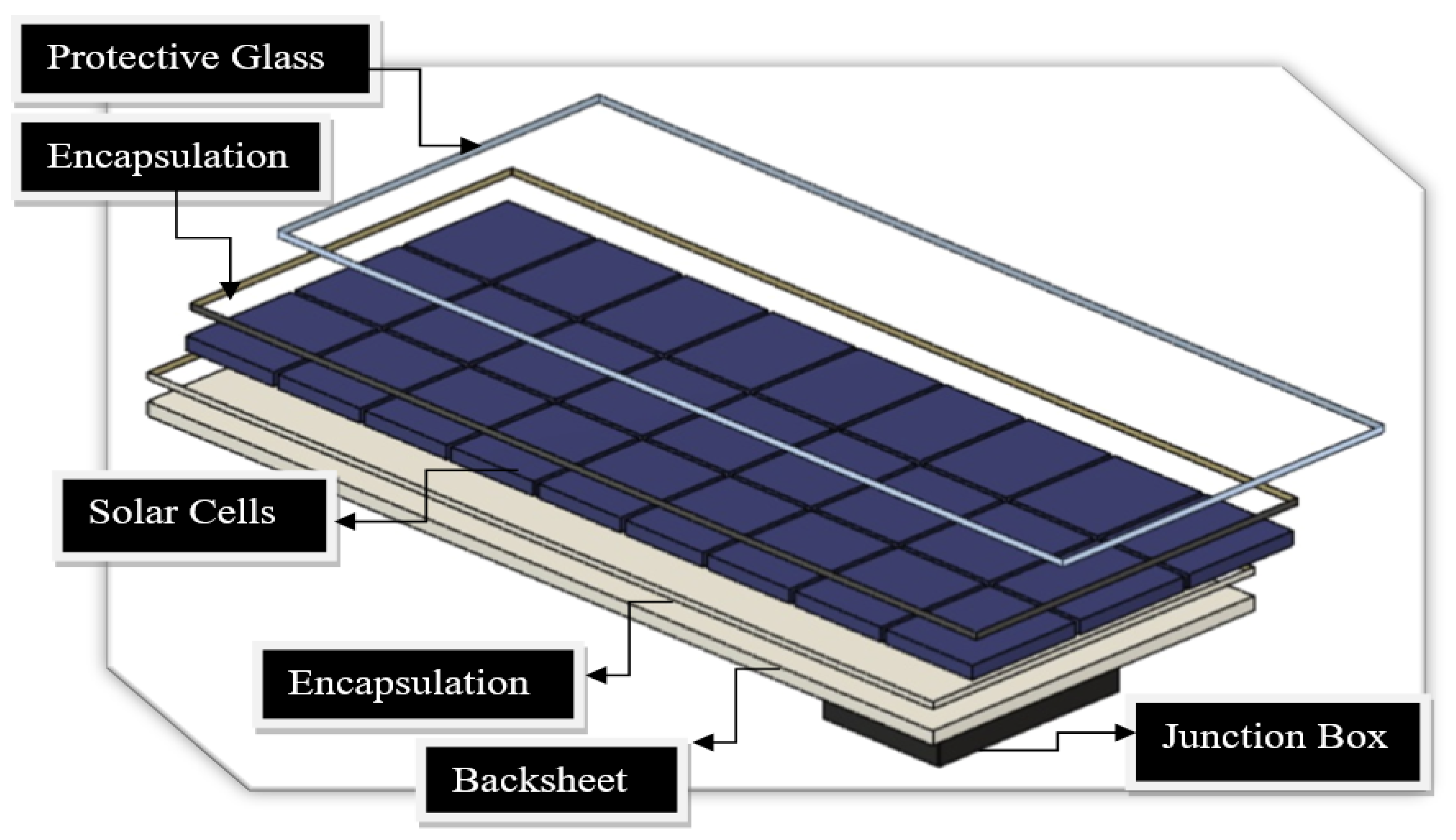
Figure 1. PV module components designed using Fusion 360 software. (The software is from Autodesk and is called Fusion 360. The version is 2.0 and Autodesk are located in San Francisco, CA, USA).
Silicon is highly purified and drawn into single crystal ingots before being sliced into wafers ranging between 0.2 to 0.5 mm thick. Residuals of crystalline silicon created during the slicing process vary based on the slicing technology. They are frequently used as crystalline ribbons to reduce manufacturing costs [4]. Once the wafer is connected to the ribbon, the solar cell is ready for testing.
2.1. Protective Glass
The protective glass in the PV module is made from tempered glass that contains a small proportion of iron oxide, not exceeding 0.05%, to allow for the transmission of sun light [20]. It is manufactured and designed to resist environmental stress factors such as a drastic change in temperature.
Gürtürk et al. [21] validated glass properties by measuring its optical transmittance and energy efficiency. They investigated two types of PV glass, one of which was rated to have a 1% higher solar transmittance. One in each type was used as a control glass and tested at a constant temperature. The others were tested at an elevated temperature that reached 120 °C. Their results showed no significant impact on energy efficiency, only a slight variation, not exceeding 2.06% at most. Afridi et al. [22] artificially formed a hotspot via shading with temperature rising to 200 °C in glass/glass and backsheet/glass PV modules and proved that the front glass of those two types was not broken or shattered despite the occurrence of severe damage like burn marks, specifically in the glass/glass PV module type. Belhaouas et al. [23] inspected twenty PV modules equipped with two different types of glass after 11 years of deployment in Bouzareah, Algeria: eight with float glass and the other twelve with textured glass. Their visual inspection showed more optical failures such as delamination in the float glass types, albeit all PV modules suffered from discolouration. Moreover, the electrical parameters of PV modules with float glass type displayed reduced values compared to those with textured glass, except for the open-circuit voltage. Nonetheless, all twenty PV modules experienced nearly the same degradation rate, at 1.04% per year.
A reduction in light transmittance is the primary failure that occurs in PV glass and is potentially caused by glass breaking or shattering or by harsh weather conditions like ultraviolet exposure and dust accumulation [24][25]. A lab experiment by Tagawa et al. [26] explored dust accumulation on glass and its effect on transmittance. Their results revealed a dramatic coarseness increment that resulted in a 32% reduction in glass transmittance after 44 min of accumulation. To protect against harmful UV wavelengths, some PV glass is doped with cerium as an additive [27]. However, King et al. [28] discovered, in a laboratory experiment, that doping cerium reduces optical transmission by up to 2%. Kempe et al. [29] conducted further experiments on the impact of removing cerium from protective glass and found that excluding cerium can raise optical transmittance by approximately 1.8% [17], which drives some manufacturers to abandon cerium in the production of PV glass. However, excluding cerium from PV glass is extremely risky; it can cause a substantial rise in the rate of delamination failure by a factor of three [29]. Consequently, when it comes to cerium, Kempe et al. [29] determined that excluding cerium will not boost electrical efficiency, and if excluded, there is a need to coat the glass with anti-reflective substances to filter out damaging ultraviolet wavelengths, predominantly below 350 nmnm.
Glass shattering can be the result of poor PV module transportation or incorrect manufacturing processes involving excessive clamping force [30][31][32][33]. Some weather conditions also contribute to PV glass degradation and failures. A study by Bora et al. [34] analysed the failure modes of PV modules in different weather conditions in India. They showed that PV modules deployed in hot areas were vulnerable to glass breakage within five years of operation. Shattering or breakage of the module’s glass allows water vapor to enter the solar cells, creating short circuits and safety risks like electrical shock [35]. This is why glass breakage failure ranked 9 out of 10 in terms of severity as it affects safety severely [35].
In addition, the temperature at the glass’s breaking point increases, which may cause hotspot failure [14]. In an investigation study by Chandel et al. [36], a PV module with glass breakage had developed hotspot failures with resulting significant power loss, which was also identified by Băjenescu and Titu-Marius [37]. Typically, a hotspot forms in a PV module when some cells receive less illumination than others, resulting in those cells dissipating energy rather than producing energy, i.e., the energy produced by the fully illuminated solar cells is dissipated by the less illuminated ones, increasing the latter cells’ temperature and causing them to operate in reverse bias [38]. Hotspot failures are not only driven by broken glass failures but also driven by shading and mismatch failures [39]. Shading failure is a common PV failure that is strongly linked with hotspot formation [40][41]. When hotspots occur, they cause permanent damage to the solar cells or other module parts, such as metal connection, EVA encapsulation, or protective glass [42][43]. Jordan et al. [15] rated PV failures based on their severity, where one is low, and ten is considered the most severe; they listed hotspots to have the highest severity rate among all PV failures.
However, Ndiaye et al. [30] investigated a PV module with broken glass operating for five years and found no hotspot that led to significant power loss. This may indicate that glass breakage was not the cause of the failure, but a subsequent consequence due to weak protection. Bansal et al. [35] investigated a PV module operating for 10 years in a mega-plant and found that glass breakage was almost certainly combined with solar cell cracking and significant power loss as a result of weak protection.
2.2. Encapsulant
Various encapsulating substances have been used in photovoltaic modules, such as polydimethylsiloxane (PDMS) and thermoplastic polyurethane (TPU) [7][44][45][46]. Manufacturers evaluate their advantages and disadvantages in terms of properties including reliability and cost before selection. For instance, PDMS demonstrates better immunity to environmental stress factors, which favoured it in the early trials of PV encapsulation [47]. Recently, manufacturers such as DuPont developed a PV encapsulant classified as an ionomer which offers 25 times more protection against potential-induced degradation (PID) failure than the typical encapsulant, ethylene-vinyl acetate (EVA). Dow Chemicals, another manufacturer, developed polyolefin-based encapsulants and has claimed they have greater electrical resistance as well as moisture protection when compared to EVA and ionomers [48][49]. Azam et al. [50] explored the degradation rate of four modules, two of which were laminated with polyvinyl butyral (PVB) encapsulant, under an accelerated ultraviolet test and found they had a 50% lower degradation rate compared to EVA.
Despite the superior protection features against environmental stress factors in more advanced encapsulating materials, EVA is still used in more than 75% of all PV modules due to its cost effectiveness [51][52]. The cost of PVB material, for instance, is about 50% more per m2 than its competitor, EVA [50]. The majority of EVA composition is vinyl acetate, with the remainder being a combination of ethylene, antioxidants, and curing agents [53][54].
However, from the historical research carried out in 1981 by Lathrop et al. [55] at Clemson University until recent literature reviews, e.g., [56][57], EVA encapsulant is the primary cause of PV degradation mechanisms. Aboagye et al. [58] recently inspected polycrystalline and monocrystalline PV modules deployed in three locations in Ghana with different weather conditions, all of which showed defects in EVA encapsulants. The same findings were noted for 43 monocrystalline PV modules mounted for ten years in Nordic weather conditions, specifically in Grimstad, Norway [59]. Nearly all 43 modules suffered from encapsulant defects, namely delamination or discolouration. In Florida, United States, 156 PV modules were inspected after 10 years of deployment and also revealed the same results as [58][59]: all 156 modules exhibited encapsulant delamination failure.
Encapsulant wear-out can result in low optical performance in PV modules, which causes a reduction in the electrical output owing to decreased light absorption and extreme light reflection [60]. The encapsulant discolouration effect begins with a drop in the short-circuit current (𝐼𝑆𝐶). The drop in 𝐼𝑆𝐶 can be as much as 40%, albeit it is not regarded as a PV failure, as it may not pose a safety hazard [61]. Still, discolouration leads to more severe failures like delamination and corrosion as a result of the release of acetic acid. The released acetic acid in turn is characteristically found responsible for the corrosion of contacts that frequently occurs after the initiation of discolouration failure [62].
With that in context, delamination can cause a substantial decrease in the amount of light absorbed, thereby leading to a significant drop in ISC. Bubble formation is one of the primary triggers of encapsulant delamination; it is formed initially during the lamination process of encapsulation due to a higher localised ratio of released volatile organic compounds [63][64]. The area affected by bubbles in the PV module operates at hotter temperatures and potentially leads to burn marks [65]. A study by Rajput et al. [66] analysed the degradation mechanism of 90 monocrystalline PV modules operated for 22 years in India; it was found that the PV modules affected by more bubbles had more power loss.
Despite ultraviolet radiation occupying a relatively small percentage in the solar spectrum, less than 4%, it is considered a major reason for the degradation of PV encapsulant material [67][68]. Due to its shorter wavelength, ultraviolet radiation possesses greater energy that can gradually degrade the encapsulant, decomposing its polymeric bonds [69]. The UV spectrum is divided into three types: UV-A, UV-B, and UV-C. In deployments, PV modules are not exposed to ultraviolet type-C but ultraviolet type-B radiation. Hence, the latter is regarded as the primary trigger of the degradation mechanism in EVA [70][71][72]. Even with the implementation of UV-blocking glass, the degradation of EVA remains significant when exposed heavily to UV-B, particularly in conjunction with other stressors such as high temperatures and humidity [29][73]. Consequently, a chemical process is instigated, resulting in the creation of acetic acid and aldehyde, which leads to a gradual darkening of the EVA material from clear to dark brown in severe instances [73][74].
Miller et al. [45] examined five types of encapsulants, exploring the degradation process after exposing them to an artificial ultraviolet source and different combination levels of humidity and temperature. Their experiments revealed that encapsulants had higher degradation rates when they were exposed to lower humidity and higher temperatures, displaying faster yellowing. Experiments for exposing PV encapsulant to ultraviolet sources with stressors were also conducted by Arularasu [75] and showed similar results to Miller et al. [45].
To account for the degree of encapsulant yellowing, a “yellowing-index” terminology, published by the International Organization for Standardization (ISO) [76], is used. Yellowing index is defined as the alteration of polymer colour toward yellow [76]. Nevertheless, Oliveira et al. [77] discovered that early degradation of EVA cannot be spotted as it may start before its colour turns yellow, i.e., the yellowing index has not experienced any modifications. This ambiguity has driven more investigations, for example [27][78][79], to explore the initial stage of EVA degradation.
The latter might be the one of reasons for Ferrara and Philipp [80] stating there is no distinct correlation between the shift in EVA’s colour and the solar cell’s electrical performance. However, Rosillo and Alonso-Garcia [81] demonstrated through experimentation that an increase in the yellowness index reduces the major electrical parameter maximum power output. The results of their study are consistent with the well-known research conducted by Pern et al. [82], which examined the electrical performance of solar cells for five different colours of EVA (clear, yellow-brown 1, yellow-brown 2, brown, and dark brown). The researchers concluded that as the EVA colour darkened, there was a gradual decrease in maximum power output, with the greatest reduction observed in the dark brown colour [71].
In addition, Dechthummarong et al. [83] took measurements of PV modules before and after they were mounted for 15 years to ascertain whether the insulation resistance still complied with the IEC 61215 standard [84]. The researchers categorised EVA discolouration into four colours: light yellow, yellow, brown, and dark brown. Their findings revealed that the modules with light yellow and yellow discolouration exhibited healthier performance with superior efficiency when compared to the brown and dark brown EVA modules. Surprisingly, the insulation resistance of all PV modules met the IEC 61215 standard, even though modules with brown and dark brown discolouration were more vulnerable to failure from corrosion, delamination, and EVA bubble formation. An investigation conducted by Diniz et al. [85] also found that modules with brown discolouration were associated with more severe and safety-related failures, including corrosion.
2.3. Solar Cells
Solar cells are connected in series and then encapsulated, typically with EVA, to provide adhesion between the solar cells and the protective glass. Failure of the solar cell mainly occurs due to the very thin profile of the silicon wafer. These thin wafers are very brittle and are prone to cracking easily during manufacturing or transportation.
Generally, microcracks of the cell cannot be detected by the naked eye. Consequently, they may spread and distribute to other cells in the module [14]. When the cracks prevent more than 8% of the cell from functioning, it may lead to a hotspot [14][86]. The active area of the cracked cell may be forced to operate in reverse bias, eventually causing a hotspot failure. Moreover, cracks are subject to expansion and seeding more cracks, especially under environmental and mechanical stress factors like hot, cold, and windy climate conditions [87][88][89][90]. Consequently, they accelerate the ageing process, showing a higher degradation rate [14]. Buerhop et al. [91] reported that PV modules with cracked cells had a greater than 10% power loss after six years of operation when compared to healthy ones. A study by Siruvuri et al. [92] developed a deep learning model based on four attributes—crack type (edge or centre), size, orientation angle (angle in degrees of the crack: horizontal vs. vertical cracks), and ambient temperature—to forecast the impact of crack severity on power loss. The outcome results were analysed and evaluated, revealing that power loss increased with increasing crack size and temperature but decreased with increasing orientation angle. However, with regards to angle orientation, their results contradicted the results of Dhimish et al. [93], where horizontal cracks were more gentle than vertical cracks or so-called parallel to busbar [94].
Conversely, snail track failure can be detected by the naked eye; this failure is so named because it is shaped like a snail’s trail. Dolara et al. [95] indicated that most snail track failures are linked to the existence of cracked cells. They also compared four PV modules with a snail track against a healthy one. In their findings, maximum power output dropped in all PV modules with a snail track, one of which had a power loss of 40% of rated power. This reduction in maximum power was caused primarily by a significant reduction in 𝐼𝑆𝐶, despite a slight increment in open-circuit voltage (VOC). This association between cracked cells and snail tracks was also stressed in a recent investigation conducted in Indonesia [96]. Duerr et al. [97] found that four degradation mechanisms trigger snail track failures, depending on the combination of the encapsulant materials, and on that basis, snail tracks should be described and categorised under PV failures rather than a single degradation mechanism.
Potential-induced degradation (PID) is another PV failure mode. First observed in Germany in 2005 [98], it degrades PV wafers and leads to the development of hotspots [12][13]. It is formed owing to polarisation differences between the PV module frame and the module’s cells. Thus, it mostly occurs in PV plants and farms where PV frames are grounded as a protective technique against fire ignition [99]. If undetected, it may lead to 100% power loss within a few years [24]. A report based in Germany stated that PID failure progresses rapidly with the release of acetic acid due to EVA discolouration [100]. Moreover, in a lab experiment by Pingel et al. [101], the PV module was found unlikely to recover from PID when operated at higher temperatures. With the rise of bifacial PV module deployment in the last decade, Molto et al. [102], reviewed the PID failure displayed in these module types. Although bifacial modules joined the PV market recently, over 30 scientific papers on such failures have been published in the literature. The review analysis of Molto et al. [102] came up with four classifications of PID failures: PID-s, Na-penetration-PID, PID-p and PID-c. Both PID-s and Na-penetration were caused by the leaning and movement of Na- Na-positive ions to the polarised cells. Involvement of Na+ ions were also found in PID-c type, which was also classified into three categories, whereas PID-p was related to the deterioration of the PV surface. Recovery of all types was found to be possible either fully or partially via dark storage or ultraviolet lighting, particularly for PID-p, but was found to be irreparable for the PID-c type [102].
Another failure that solar cells might experience is through disconnection of solar cell busbars or ribbons. This type of failure occurs because of a manufacturing defect; it is also driven by excessive heat due to long partial shading and can produce excessive leakage current. When undetected, it increases cell temperature and forms a hotspot [103]. Such failures can be detected by an infrared (IR) camera or by monitoring the output I–V curve. When this failure occurs, the output power typically decreases by ~35%. With progression, the power will decrease by ~46% [104]. Consequently, the solder bond will become extremely hot, leading to burn marks and discolouration of the EVA encapsulant [105]. In the worst-case scenario, the protective glass will be broken, with visible burn marks on the PV module’s backsheet blocking the current path and initiating an electrical arc and fire, causing irreversible damage [14].
Colvin et al. [106] explored interconnection failures depending on cut location in the PV module and irradiance. They investigated cuts in busbars that connect cells in the centre of the PV module and cuts in outer busbars (at the edge). Results showed that outer busbar cuts are more severe and reduce module power output by nearly double compared to cuts in centred busbars. Their findings were justified by the fact that alternative busbars that can carry the captured photocurrents are limited to one when cuts occur at the outer busbar, whereas in inner cuts, there is more than one alternative busbar that can act in place. Majd et al. [107] explored failure immunity in three common interconnection types in PV modules through FEM simulation: the first one is the conventional interconnection known as front-to-back interconnection; the second type is the light-capturing type, which is named due to the recapturing of lost photons via reflection; the third type is the multi-busbar, which uses its rounder shape to reflect the lost light to the cell. Among the three, the multi-busbar type showed 15 per cent higher immunity against ribbon and busbar failures.
Thus, as with most PV failures, early detection is essential to assure a reliable and safe operation of the PV system.
2.4. Backsheet
The backsheet is the last protection layer of the PV module that provides construction support to the PV module. It shields the module’s electrical parts from short-circuit failure, ensuring perfect electrical insulation from various environmental stress factors such as water ingress from high relative humidity [108]. Failures and degradation in the backsheet can appear as cracks, discolouration, delamination, bubbles, and burn marks [100].
The major cause of burn mark failures are hotspots, and this may lead the PV module to catch fire. For this purpose, a study conducted by Cancelliere and Liciotti [67] investigated fire reactions with four material arrangements on the basis of a PET (polyethylene terephthalate) backsheet: three layers (PET/PET/primer), four layers (PET/aluminium/PET/primer), three layers (fluoro-coating/PET/EVA), and PET layer with an outside and inside coating. Two backsheets—PET monolayer with an inside and outside coating and the four-layer backsheet (PET/aluminium/PET/primer)—reacted slower to fire and had fewer damaged areas with no or less harm to the EVA encapsulant. However, the monolayer with an inside and outside coating backsheet is favoured over the other as aluminium is electrically conductive and may result in less power production. PET backsheets were also compared for cracking against backsheets made of PP (polypropylene) by Oreski et al. [109]. That comparative study employed an accelerated stress test to explore if PP backsheets have the same immunity as PET backsheets. They found that PP exhibited cracking after the same exposure time as PET, which makes it a reliable substitution for PV backsheets. Further to this, Elfaqih et al. [110] suggested mixing PP backsheets with 5% carbon fibre to provide greater strength and longer reliability against failure. They came up with their proposal after they investigated PP and PPCF (PP supported with carbon fibre) and found that the PPCF backsheet has higher tensile strength.
Investigations of PV module backsheets deployed in outdoor conditions were also conducted by Pascual et al. [111]. In their study, PV modules were deployed in an 8 MW plant. All of them were from the same manufacturer but with two backsheet types: PVF (fluorinated) and polyamide. The PV modules were deployed in 2011 and investigated after six years of operation. Visual inspection revealed that 14% of modules with polyamide backsheets suffered from cracks. Furthermore, polyamide backsheets were susceptible to chalking, which is the decomposition of backsheet material into white powder and is considered a warning sign of abnormal degradation [112]. More than 90% of inspected PV modules with polyamide backsheets degraded by chalking, while none of the PVF backsheets did. The strength of the PVF backsheet might be one of the reasons that has driven research efforts, e.g., [113][114], to search for effective ingredients to be used in accelerated stress tests.
Regarding cracking, Mühleisen [115] developed a solution based on polyurethane paint to be coated at the early onset of backsheet cracking. The coating was examined for nearly two years in outdoor conditions and was also tested under accelerated stress tests. Their results showed a significant reduction in crack progression in coated backsheets compared to uncoated ones. The study of Mühleisen [115] is not the first of its kind, as Beaucarne et al. [116] also fabricated a coated solution of a flowable silicone sealant that can act in place to avoid early replacement of PV modules. They applied the solution on PV modules operated for less than 8 years with heavy backsheet cracks. These modules included four types of backsheet: co-extruded polyamide, PVF, PVDF, and PET. The cracked backsheet modules were tested for insulation resistance and none of them passed the required standard level. After applying the coating, all of them were restored to a healthy level of insulation resistance even after applying accelerated stress tests for a thousand hours.
2.5. Junction Box and Bypass Diodes
A junction box (J-box) is attached to the PV module through adhesive material to regulate and provide a safe flow of the collected photocurrents into the PV module [117]. To guarantee the correct flow path of the current, bypass diodes are also installed inside the J-box in different configurations: overlap and non-overlap [118]. Failures in the J-box are mainly caused by low wiring quality, blown bypass diodes, corrosion, and poor bonding to the PV module (delamination), caused primarily by high humidity [56]. Failure of the J-box may result in zero output of electricity, as was found by Bakir [119] in a recent assessment of a 23 MW PV plant mounted in Turkey. Many studies, e.g., [120][121], have come up with novel techniques to monitor and protect J-boxes from failures. Most J-box failures allow for the ingress of water vapor, causing serious safety issues, such as initiating an electrical arc or causing hotspots [14]. Ong et al. [122] listed J-box failures among the root causes of fire ignition in PV modules. Han et al. [123] investigated the condition of 177 monocrystalline PV modules that operated for 22 years in a humid climate with an average temperature of 27.5 °C. Most of the junction boxes of the modules had been seriously damaged and needed replacing.
Furthermore, junction boxes can degrade at a faster rate when exposed to large variations in ambient temperature during the year. Daher et al. [124] evaluated the reliability of a 9-year PV system (270 modules) installed off-grid that was expected to produce 62 kW in Ali Adde town, Djibouti. The PV system was exposed to the town’s high temperatures with dramatic variation from winter (average temperature is 26.7 °C) to summer with an average of 38 °C. Out of 270 modules, 39% were diagnosed with adhesive junction box failure.
On the other hand, cold climates with high relative humidity like that of Grimstad, Norway, led to the corrosion of junction boxes [59]. J-boxes and metal parts of PV modules operating in so-called floatovoltaics structures, such as PV systems deployed on the water in a floating construction, are also at higher risk of corrosion [125]. This urged Ghosh [126] to recommend that J-boxes should have a protection rating of IP67 when attached to PV modules mounted in a water-based environment. Unsurprisingly, dust has also been found to corrode the PV module’s junction box. Tabet et al. [127] inspected a module operating in a dusty environment for six years, finding that the J-box failed because of corrosion. This is in agreement with the finding of Lin and Zhan [128] that water-dissolvable salts represent more than 59% of dust composition, in which, whenever stuck to metal, they react and cause corrosion, primarily in humid environments.
Several PV failures were found to form hotspots, making it necessary to protect the PV module. One means of protection is to use a bypass diode, although it has been criticised for being neither safe nor effective [42][129][130]. The existence of a bypass diode enables the current to flow over the defective solar cells, thereby protecting the PV module from thermal increases and hotspots. This is one of the main explanations why some PV manufacturers, such as AE-Solar, a German PV manufacturer, attach a bypass diode to each PV cell [131]. One of the recurrent reasons for blown bypass diodes is the increase in their temperature due to long-term shading [132][133]. Also, it was indicated by Bansal et al. [56] that those bypass diodes that were exposed to overirradiance, in particular over 1400 Wm−2,Wm−2, are expected to be blown due to excessive currents.
Failure to detect poor bypass diodes may lead to serious safety issues [133][134]. Since bypass diodes are used to avoid PV failures that lead to hotspotting, whenever they fail, the module loses its means of protection, becomes vulnerable, and, in the worst scenario, initiates fire [135][136]. Bakir [137] used an infrared imaging detection technique where he attached thermal cameras to a drone to be flown over three solar plants that ranged between 2 and 3.5 MW. One of the plants had three PV modules with failed bypass diodes and as a result, their operating temperature increased by an average of 19.7 C. It was shown by Ghosh et al. [138] that the operating temperature of PV cells undergoing shading failure decreases by nearly 50% when bypass diodes are functioning. Their experimental study aimed to explore if total cross-tied (TCT) array configurations were effective in preventing hotspots by allowing the bypass diodes to respond promptly in cases of shading. The study also showed that bypass diodes were only functioning if more than one cell was affected by shading and, therefore, further investigations are required to pinpoint the optimal configuration of PV arrays that is able to activate bypass diodes even in the case of one shaded cell, such as situations of fouling by bird droppings.
PV failures can be classified based on the components affected. The same PV failure mechanism can be seen or experienced in more than one component due to the similarity of the materials; e.g., EVA is present in encapsulants and also in backsheets. Furthermore, EVA defects are usually considered an early sign of PV module degradation and failure as EVA, alongside PV glass, represents the first defence line against weather stressors. Unlike snail tracks in PV cells, corrosion is another failure mechanism that can attack more than one component, such as solar cell solders, bypasses, and junction boxes, especially in humid environments.
The hotspot failure mechanism is considered the most severe failure and leads to catastrophic consequences. It deteriorates all PV module components if undetected, and a PV module affected by an elevated level of hotspots cannot reverse the degradation and often requires replacement. Thus, identifying the initial stages of PV degradation can prevent potential hazards through proactive maintenance. Sometimes, it is even more effective to substitute a PV module that displays the early onset of deterioration as it will guarantee all deployed modules in PV plants continue generating the healthier (expected) power, regardless if their condition complies with the IEC 61215 standard [84].
References
- Li, L.; Lin, J.; Wu, N.; Xie, S.; Meng, C.; Zheng, Y.; Wang, X.; Zhao, Y. Review and outlook on the international renewable energy development. Energy Built Environ. 2022, 3, 139–157.
- Green, M.A. How did solar cells get so cheap? Joule 2019, 3, 631–633.
- PSE Projects, Photovoltaics Report; Fraunhofer Institute for Solar Energy Systems ISE: Freiburg im Breisgau, Germany, 2022.
- Goetzberger, A.; Hebling, C.; Schock, H.-W. Photovoltaic materials, history, status and outlook. Mater. Sci. Eng. R Rep. 2003, 40, 1–46.
- Green, M.A.; Dunlop, E.D.; Hohl-Ebinger, J.; Yoshita, M.; Kopidakis, N.; Ho-Baillie, A.W. Solar cell efficiency tables (version 55). Prog. Photovolt. Res. Appl. 2019, 28, 3–15.
- Peike, C.; Hädrich, I.; Weiß, K.-A.; Dürr, I. Overview of PV module encapsulation materials. Photovolt. Int. 2013, 19, 85–92.
- Ma, S.; Yuan, G.; Zhang, Y.; Yang, N.; Li, Y.; Chen, Q. Development of encapsulation strategies towards the commercialization of perovskite solar cells. Energy Environ. Sci. 2022, 15, 13–55.
- Wang, H.; Cheng, X.; Yang, H.; He, W.; Chen, Z.; Xu, L.; Song, D. Potential-induced degradation: Recombination behavior, temperature coefficients and mismatch losses in crystalline silicon photovoltaic power plant. Sol. Energy 2019, 188, 258–264.
- Vázquez, M.; Rey-Stolle, I. Photovoltaic module reliability model based on field degradation studies. Prog. Photovolt. Res. Appl. 2008, 16, 419–433.
- Daher, D.H.; Gaillard, L.; Ménézo, C. Experimental assessment of long-term performance degradation for a PV power plant operating in a desert maritime climate. Renew. Energy 2022, 187, 44–55.
- Wohlgemuth, J. IEC 61215: What It Is and Isn’t (Presentation); National Renewable Energy Lab (NREL): Golden, CO, USA, 2012.
- Barretta, C.; Macher, A.E.; Ascencio-Vásquez, J.; Köntges, M.; Topič, M.; Oreski, G. Degradation of Crystalline Silicon Photovoltaic Modules Installed in Different Climates. In Proceedings of the IEEE 49th Photovoltaics Specialists Conference (PVSC) 2022, Philadelphia, PA, USA, 5–10 June 2022; pp. 680–682.
- Dhimish, M.; Tyrrell, A.M. Power loss and hotspot analysis for photovoltaic modules affected by potential induced degradation. NPJ Mater. Degrad. 2022, 6, 11.
- Köntges, M.; Kurtz, S.; Packard, C.; Jahn, U.; Berger, K.A.; Kato, K.; Friesen, T.; Liu, H.; Van Iseghem, M. Review of Failures of Photovoltaic Modules IEA PVPS Task 13 External Final Report March 2014. IEA-PVPS T13-01. 2014. Available online: https://iea-pvps.org/wp-content/uploads/2020/01/IEA-PVPS_T13-01_2014_Review_of_Failures_of_Photovoltaic_Modules_Final.pdf (accessed on 3 August 2023).
- Jordan, D.C.; Silverman, T.J.; Wohlgemuth, J.H.; Kurtz, S.R.; VanSant, K.T. Photovoltaic failure and degradation modes. Prog. Photovolt. Res. Appl. 2017, 25, 318–326.
- Madeti, S.R.; Singh, S. A comprehensive study on different types of faults and detection techniques for solar photovoltaic system. Sol. Energy 2017, 158, 161–185.
- Pillai, D.S.; Rajasekar, N. A comprehensive review on protection challenges and fault diagnosis in PV systems. Renew. Sustain. Energy Rev. 2018, 91, 18–40.
- Osmani, K.; Haddad, A.; Lemenand, T.; Castanier, B.; Alkhedher, M.; Ramadan, M. A critical review of PV systems’ faults with the relevant detection methods. Energy Nexus 2023, 12, 100257.
- Heywang, W.; Zaininger, K.H. Silicon: The semiconductor material. In Silicon; Springer: Berlin/Heidelberg, Germany, 2004; pp. 25–42.
- Kılıç, A.; Öztürk, A. Güneş Enerjisi; Kipaş Dağıtımcılık: Istanbul, Turkey, 1983.
- Gürtürk, M.; Benli, H.; Ertürk, N.K. Determination of the effects of temperature changes on solar glass used in photovoltaic modules. Renew. Energy 2020, 145, 711–724.
- Afridi, M.; Kumar, A.; ibne Mahmood, F.; Tamizhmani, G. Hotspot testing of glass/backsheet and glass/glass PV modules pre-stressed in extended thermal cycling. Sol. Energy 2023, 249, 467–475.
- Belhaouas, N.; Mehareb, F.; Kouadri-Boudjelthia, E.; Assem, H.; Bensalem, S.; Hadjrioua, F.; Aissaoui, A.; Hafdaoui, H.; Chahtou, A.; Bakria, K. The performance of solar PV modules with two glass types after 11 years of outdoor exposure under the mediterranean climatic conditions. Sustain. Energy Technol. Assess. 2022, 49, 101771.
- Tsanakas, J.A.; Ha, L.; Buerhop, C. Faults and infrared thermographic diagnosis in operating c-Si photovoltaic modules: A review of research and future challenges. Renew. Sustain. Energy Rev. 2016, 62, 695–709.
- Enaganti, P.K.; Bhattacharjee, A.; Ghosh, A.; Chanchangi, Y.N.; Chakraborty, C.; Mallick, T.K.; Goel, S. Experimental investigations for dust build-up on low-iron glass exterior and its effects on the performance of solar PV systems. Energy 2022, 239, 122213.
- Tagawa, K.; Kutani, A.; Qinglin, P. Effect of sand erosion of glass surface on performances of photovoltaic module. In Proceedings of the Sustainable Research and Innovation Conference, Nairobi, Kenya, 5–7 October 2022; pp. 75–77.
- King, D.; Quintana, M.; Kratochvil, J.; Ellibee, D.; Hansen, B. Photovoltaic module performance and durability following long-term field exposure. Prog. Photovolt. Res. Appl. 2000, 8, 241–256.
- King, D.; Pern, F.; Pitts, J.; Bingham, C.; Czanderna, A. Optical changes in cerium-containing glass as a result of accelerated exposure testing . In Proceedings of the Conference Record of the Twenty Sixth IEEE Photovoltaic Specialists Conference-1997, Anaheim, CA, USA, 29 September–3 October 1997; pp. 1117–1120.
- Kempe, M.D.; Moricone, T.; Kilkenny, M. Effects of cerium removal from glass on photovoltaic module performance and stability. In Proceedings of the Reliability of Photovoltaic Cells, Modules, Components, and Systems II; SPIE: Bellingham, DC, USA, 2009; p. 74120Q.
- Ndiaye, A.; Charki, A.; Kobi, A.; Kébé, C.M.F.; Ndiaye, P.A.; Sambou, V. Degradations of silicon photovoltaic modules: A literature review. Sol. Energy 2013, 96, 140–151.
- Quansah, D.A.; Adaramola, M.S. Comparative study of performance degradation in poly- and mono-crystalline-Si solar PV modules deployed in different applications. Int. J. Hydrogen Energy 2018, 43, 3092–3109.
- Dietrich, S.; Pander, M.; Ebert, M.; Bagdahn, J. Mechanical assessment of large photovoltaic modules by test and finite element analysis. In Proceedings of the 23rd European Photovoltaic Solar Energy Conference, Valencia, Spain, 1–5 September 2008.
- Cavieres, R.; Barraza, R.; Estay, D.; Bilbao, J.; Valdivia-Lefort, P. Automatic soiling and partial shading assessment on PV modules through RGB images analysis. Appl. Energy 2022, 306, 117964.
- Bora, B.; Sastry, O.S.; Kumar, R.; Dubey, R.; Chattopadhyay, S.; Vasi, J.; Mondal, S.; Prasad, B. Failure mode analysis of PV modules in different climatic conditions. IEEE J. Photovolt. 2020, 11, 453–460.
- Bansal, N.; Jaiswal, S.P.; Singh, G. Long term operational performance and experimental on-field degradation measurement of 10 MW PV plant in remote location in India. Energy Sustain. Dev. 2022, 67, 135–150.
- Chandel, S.S.; Nagaraju Naik, M.; Sharma, V.; Chandel, R. Degradation analysis of 28 year field exposed mono-c-Si photovoltaic modules of a direct coupled solar water pumping system in western Himalayan region of India. Renew. Energy 2015, 78, 193–202.
- Titu-Marius, B. Some reliability aspects of photovoltaic modules. In Reliability and Ecological Aspects of Photovoltaic Modules; IntechOpen: Rijeka, Croatia, 2020.
- Castaner, L.; Silvestre, S. Modelling Photovoltaic Systems Using PSpice; John Wiley and Sons: Hoboken, NJ, USA, 2002.
- Deng, S.; Zhang, Z.; Ju, C.; Dong, J.; Xia, Z.; Yan, X.; Xu, T.; Xing, G. Research on hot spot risk for high-efficiency solar module. Energy Procedia 2017, 130, 77–86.
- Meyer, E.L.; Van Dyk, E.E. The effect of reduced shunt resistance and shading on photovoltaic module performance. In Proceedings of the Conference Record of the Thirty-First IEEE Photovoltaic Specialists Conference, Lake Buena Vista, FL, USA, 3–7 January 2005; pp. 1331–1334.
- Vankadara, S.K.; Chatterjee, S.; Balachandran, P.K. An accurate analytical modeling of solar photovoltaic system considering Rs and Rsh under partial shaded condition. Int. J. Syst. Assur. Eng. Manag. 2022, 13, 2472–2481.
- Ghanbari, T. Permanent partial shading detection for protection of photovoltaic panels against hot spotting. IET Renew. Power Gener. 2016, 11, 123–131.
- Jadin, M.S.B.; Safian, S.F.A.; Ghazali, K.H.; Ven, T.L.; Shah, A.S.M. Hotspot Detection in Photovoltaic Array Using Thermal Imaging Method. In Proceedings of the 6th International Conference on Electrical, Control and Computer Engineering, Kuantan, Malaysia, 23 August 2022; pp. 101–107.
- Hasan, O.; Arif, A. Performance and life prediction model for photovoltaic modules: Effect of encapsulant constitutive behavior. Sol. Energy Mater. Sol. Cells 2014, 122, 75–87.
- Miller, D.C.; Bokria, J.G.; Burns, D.M.; Fowler, S.; Gu, X.; Hacke, P.L.; Honeker, C.C.; Kempe, M.D.; Köhl, M.; Phillips, N.H. Degradation in photovoltaic encapsulant transmittance: Results of the first PVQAT TG5 artificial weathering study. Prog. Photovolt. Res. Appl. 2019, 27, 391–409.
- López-Escalante, M.; Caballero, L.J.; Martín, F.; Gabás, M.; Cuevas, A.; Ramos-Barrado, J. Polyolefin as PID-resistant encapsulant material in PV modules. Sol. Energy Mater. Sol. Cells 2016, 144, 691–699.
- Kempe, M. Overview of scientific issues involved in selection of polymers for PV applications. In Proceedings of the 2011 37th IEEE Photovoltaic Specialists Conference, Seattle, WA, USA, 19–24 June 2011; pp. 000085–000090.
- Habersberger, B.M.; Hacke, P.; Madenjian, L.S. Evaluation of the PID-s susceptibility of modules encapsulated in materials of varying resistivity. In Proceedings of the 2018 IEEE 7th World Conference on Photovoltaic Energy Conversion (WCPEC) (A Joint Conference of 45th IEEE PVSC, 28th PVSEC & 34th EU PVSEC), Amsterdam, The Netherlands, 10–15 June 2018; pp. 3807–3809.
- Kapur, J.; Stika, K.M.; Westphal, C.S.; Norwood, J.L.; Hamzavytehrany, B. Prevention of potential-induced degradation with thin ionomer film. IEEE J. Photovolt. 2014, 5, 219–223.
- Azam, M.F.; Shahzad, N.; Rafique, A.; Ayub, M.; Khalid, H.A.; Waqas, A. Accelerated UV stress testing and characterization of PV-modules: Reliability analysis using different encapsulants and glass sheets. Sustain. Energy Technol. Assess. 2023, 56, 103119.
- Peike, C.; Purschke, L.; Weiss, K.-A.; Köhl, M.; Kempe, M. Towards the origin of photochemical EVA discoloration. In Proceedings of the 2013 IEEE 39th Photovoltaic Specialists Conference (PVSC), Tampa, FL, USA, 16–21 June 2013; pp. 1579–1584.
- Kyranaki, N.; Smith, A.; Yendall, K.; Hutt, D.A.; Whalley, D.C.; Gottschalg, R.; Betts, T.R. Damp-heat induced degradation in photovoltaic modules manufactured with passivated emitter and rear contact solar cells. Prog. Photovolt. Res. Appl. 2022, 30, 1061–1071.
- Badiee, A.; Ashcroft, I.; Wildman, R.D. The thermo-mechanical degradation of ethylene vinyl acetate used as a solar panel adhesive and encapsulant. Int. J. Adhes. Adhes. 2016, 68, 212–218.
- Desai, U.; Sharma, B.K.; Singh, A.; Singh, A. A comparison of evolution of adhesion mechanisms and strength post damp-heat aging for a range of VA content in EVA encapsulant with photovoltaic backsheet. Sol. Energy 2022, 231, 908–920.
- Lathrop, J.W.; Hartman, R.A.; Saylor, C.R. Investigation of Reliability Attributes and Accelerated Stress Factors on Terrestrial Solar Cells. 1981. Available online: https://ntrs.nasa.gov/citations/19810011041 (accessed on 3 August 2023).
- Bansal, N.; Jaiswal, S.P.; Singh, G. Comparative investigation of performance evaluation, degradation causes, impact and corrective measures for ground mount and rooftop solar PV plants—A review. Sustain. Energy Technol. Assess. 2021, 47, 101526.
- Manganiello, P.; Balato, M.; Vitelli, M. A survey on mismatching and aging of PV modules: The closed loop. IEEE Trans. Ind. Electron. 2015, 62, 7276–7286.
- Bansal, N.; Jaiswal, S.P.; Singh, G. Prolonged degradation and reliability assessment of installed modules operational for 10 years in 5 MW PV plant in hot semi-arid climate. Energy Sustain. Dev. 2022, 68, 373–389.
- Segbefia, O.K.; Akhtar, N.; Sætre, T.O. Defects and fault modes of field-aged photovoltaic modules in the Nordics. Energy Rep. 2023, 9, 3104–3119.
- Stark, W.; Jaunich, M. Investigation of Ethylene/Vinyl Acetate Copolymer (EVA) by thermal analysis DSC and DMA. Polym. Test. 2011, 30, 236–242.
- IEC 60050-191; International Electrotechnical Vocabulary: Chapter 191: Dependability and Quality of Service. International Electrotechnical Commission: Geneva, Switzerland, 1990.
- Gok, A.; Gordon, D.A.; Wang, M.; French, R.H.; Bruckman, L.S. Degradation Science and Pathways in PV Systems. In Durability and Reliability of Polymers and Other Materials in Photovoltaic Modules; Elsevier: Amsterdam, The Netherlands, 2019; pp. 47–93.
- Perret-Aebi, L.E.; Li, H.Y.; Théron, R.; Roeder, G.; Luo, Y.; Turlings, T.; Lange, R.F.M.; Ballif, C. Insights on EVA lamination process: Where do the Bubbles Come from. In Proceedings of the 25th European Photovoltaic Solar Energy Conference and Exhibition, Valencia, Spain, 6–10 September 2010.
- Karthikeyan, S.; Ajay, G.B.; Ahamed, N.R.; Sharun, A. Edge AI–Based Aerial Monitoring. In Applied Edge AI: Concepts, Platforms, and Industry Use Cases; Auerbach Publications: Boca Raton, FL, USA; CRC Press: Boca Raton, FL, USA, 2022.
- Shrestha, S.M.; Mallineni, J.K.; Yedidi, K.R.; Knisely, B.; Tatapudi, S.; Kuitche, J.; TamizhMani, G. Determination of dominant failure modes using FMECA on the field deployed c-Si modules under hot-dry desert climate. IEEE J. Photovolt. 2014, 5, 174–182.
- Rajput, P.; Tiwari, G.N.; Sastry, O.S.; Bora, B.; Sharma, V. Degradation of mono-crystalline photovoltaic modules after 22 years of outdoor exposure in the composite climate of India. Sol. Energy 2016, 135, 786–795.
- de Oliveira, M.C.C.; Cardoso, A.S.A.D.; Viana, M.M.; Lins, V.d.F.C. The causes and effects of degradation of encapsulant ethylene vinyl acetate copolymer (EVA) in crystalline silicon photovoltaic modules: A review. Renew. Sustain. Energy Rev. 2018, 81, 2299–2317.
- Frederick, J.; Snell, H.; Haywood, E. Solar ultraviolet radiation at the earth’s surface. Photochem. Photobiol. 1989, 50, 443–450.
- Klampaftis, E.; Congiu, M.; Robertson, N.; Richards, B.S. Luminescent ethylene vinyl acetate encapsulation layers for enhancing the short wavelength spectral response and efficiency of silicon photovoltaic modules. IEEE J. Photovolt. 2011, 1, 29–36.
- Kamel, M.S.A.; Oelgemöller, M.; Jacob, M.V. Sustainable plasma polymer encapsulation materials for organic solar cells. J. Mater. Chem. A 2022, 10, 4683–4694.
- Segbefia, O.K. Temperature profiles of field-aged photovoltaic modules affected by optical degradation. Heliyon 2023, 9, e19566.
- Holley, W.H.; Agro, S.C.; Galica, J.P.; Thoma, L.A.; Yorgensen, R.S.; Ezrin, M.; Klemchuk, P.; Lavigne, G. Investigation into the causes of browning in EVA encapsulated flat plate PV modules. In Proceedings of the 1994 IEEE 1st World Conference on Photovoltaic Energy Conversion-WCPEC (A Joint Conference of PVSC, PVSEC and PSEC), Waikoloa, HI, USA, 5–9 December 1994; pp. 893–896.
- Jiang, S.; Wang, K.; Zhang, H.; Ding, Y.; Yu, Q. Encapsulation of PV modules using ethylene vinyl acetate copolymer as the encapsulant. Macromol. React. Eng. 2015, 9, 522–529.
- Noman, M.; Tu, S.; Ahmad, S.; Zafar, F.U.; Khan, H.A.; Rehman, S.U.; Waqas, M.; Khan, A.D.; Rehman, O.U. Assessing the reliability and degradation of 10–35 years field-aged PV modules. PLoS ONE 2022, 17, e0261066.
- Arularasu, P. Combined UV-Temperature-Humidity Accelerated Testing of PV Modules: Reliability of UV-Cut and UV-Pass EVA Encapsulants; Arizona State University: Tempe, AZ, USA, 2019.
- ISO 17223; Plastics—Determination of Yellowness Index and Change in Yellowness Index. ISO: Geneva, Switzerland, 2014.
- de Oliveira, M.C.C.; Cassini, D.A.; Diniz, A.S.A.C.; Soares, L.G.; Viana, M.M.; Kazmerski, L.L.; Lins, V.d.F.C. Comparison and analysis of performance and degradation differences of crystalline-Si photovoltaic modules after 15-years of field operation. Sol. Energy 2019, 191, 235–250.
- Yong, H.; Minemoto, T.; Takahashi, T. Dependence of Photovoltage on Incident Photon Energies Investigated by Photo-assisted Kelvin Probe Force Microscopy on Cu (In, Ga) Se 2 Solar Cells. In Proceedings of the 2018 IEEE 7th World Conference on Photovoltaic Energy Conversion (WCPEC) (A Joint Conference of 45th IEEE PVSC, 28th PVSEC & 34th EU PVSEC), Hilto Waikoloa Village, United States, 10–15 June 2018; pp. 1966–1969.
- Adothu, B.; Chattopadhyay, S.; Bhatt, P.; Hui, P.; Costa, F.R.; Mallick, S. Early-stage identification of encapsulants photobleaching and discoloration in crystalline silicon photovoltaic module laminates. Prog. Photovolt. Res. Appl. 2020, 28, 767–778.
- Ferrara, C.; Philipp, D. Why Do PV Modules Fail? Energy Procedia 2012, 15, 379–387.
- Rosillo, F.; Alonso-Garcia, M. Evaluation of color changes in PV modules using reflectance measurements. Sol. Energy 2019, 177, 531–537.
- Pern, F.; Czanderna, A.; Emery, K.; Dhere, R. Weathering degradation of EVA encapsulant and the effect of its yellowing on solar cell efficiency. In Proceedings of the the Conference Record of the Twenty-Second IEEE Photovoltaic Specialists Conference-1991, Las Vegas, NV, USA, 7–11 October 1991; pp. 557–561.
- Dechthummarong, C.; Wiengmoon, B.; Chenvidhya, D.; Jivacate, C.; Kirtikara, K. Physical deterioration of encapsulation and electrical insulation properties of PV modules after long-term operation in Thailand. Sol. Energy Mater. Sol. Cells 2010, 94, 1437–1440.
- Photovoltaic, C.S.T. Modules—Design Qualification and Type Approval. IEC 2005, 1215, 2005.
- Diniz, A.S.A.; Cassini, D.A.; de Oliveira, M.C.; de Lins, V.F.; Viana, M.M.; Braga, D.S.; Kazmerski, L.L. Evaluation of Performance Losses and Degradation of Aged Crystalline Si Photovoltaic Modules Installed in Minas Gerais (Brazil). In Renewable Energy and Sustainable Buildings; Springer: Berlin/Heidelberg, Germany, 2020; pp. 29–46.
- Dhimish, M. Micro cracks distribution and power degradation of polycrystalline solar cells wafer: Observations constructed from the analysis of 4000 samples. Renew. Energy 2020, 145, 466–477.
- Eslami Majd, A.; Ekere, N.N. Crack initiation and growth in PV module interconnection. Sol. Energy 2020, 206, 499–507.
- Grunow, P.; Clemens, P.; Hoffmann, V.; Litzenburger, B.; Podlowski, L. Influence of micro cracks in multi-crystalline silicon solar cells on the reliability of PV modules. In Proceedings of the 20th EUPVSEC, Barcelona, Spain, 6–10 June 2005; pp. 2042–2047.
- BrightSpot Automation, L.L.C.; Westford, M.A. Solar panel design factors to reduce the impact of cracked cells and the tendency for crack propagation. In Proceedings of the NREL PV Module Reliability Workshop, Denver, CO, USA, 4 February 2015.
- Sander, M.; Dietrich, S.; Pander, M.; Schweizer, S.; Ebert, M.; Bagdahn, J. Investigations on crack development and crack growth in embedded solar cells. Reliab. Photovolt. Cells Modul. Compon. Syst. IV 2011, 8112, 811209.
- Buerhop, C.; Schlegel, D.; Vodermayer, C.; Nieß, M. Quality control of PV-modules in the field using infrared-thermography. In Proceedings of the 26th European Photovoltaic Solar Energy Conference, Hamburg, Germany, 5–9 September 2011; pp. 3894–3897.
- Siruvuri, S.V.; Budarapu, P.R.; Paggi, M. Influence of cracks on fracture strength and electric power losses in Silicon solar cells at high temperatures: Deep machine learning and molecular dynamics approach. Appl. Phys. A 2023, 129, 408.
- Dhimish, M.; Holmes, V.; Mehrdadi, B.; Dales, M. The impact of cracks on photovoltaic power performance. J. Sci. Adv. Mater. Devices 2017, 2, 199–209.
- Sohail, A.; Ul Islam, N.; Ul Haq, A.; Ul Islam, S.; Shafi, I.; Park, J. Fault detection and computation of power in PV cells under faulty conditions using deep-learning. Energy Rep. 2023, 9, 4325–4336.
- Dolara, A.; Leva, S.; Manzolini, G.; Ogliari, E. Investigation on performance decay on photovoltaic modules: Snail trails and cell microcracks. IEEE J. Photovolt. 2014, 4, 1204–1211.
- Sinaga, R. Turnitin: A Preliminary Study of Common Defects of Photovoltaic Modules in West Timor, Indonesia. In Proceedings of the IOP Conference Series: Earth and Environmental Science 2020, Bogor, Indonesia, 1 July 2020; Volume 542, p. 012041.
- Duerr, I.; Bierbaum, J.; Metzger, J.; Richter, J.; Philipp, D. Silver Grid Finger Corrosion on Snail Track affected PV Modules—Investigation on Degradation Products and Mechanisms. Energy Procedia 2016, 98, 74–85.
- Swanson, R.; Cudzinovic, M.; DeCeuster, D.; Desai, V.; Jürgens, J.; Kaminar, N.; Mulligan, W.; Rodrigues-Barbarosa, L.; Rose, D.; Smith, D. The surface polarization effect in high-efficiency silicon solar cells. In Proceedings of the 15th PVSEC, Shanghai, China, 10–15 October 2005.
- Yamaguchi, S.; Masuda, A.; Marumoto, K.; Ohdaira, K. Mechanistic Understanding of Polarization-Type Potential-Induced Degradation in Crystalline-Silicon Photovoltaic Cell Modules. Adv. Energy Sustain. Res. 2023, 4, 2200167.
- Köntges, M.; Oreski, G.; Jahn, U.; Herz, M.; Hacke, P.; Weiß, K.-A. Assessment of Photovoltaic Module Failures in the Field: International Energy Agency Photovoltaic Power Systems Programme: IEA PVPS Task 13, Subtask 3: Report IEA-PVPS T13-09: 2017; International Energy Agency: Paris, France, 2017.
- Pingel, S.; Janke, S.; Frank, O. Recovery methods for modules affected by potential induced degradation (PID). In Proceedings of the 27th European Photovoltaic Solar Energy Conference and Exhibition (Frankfurt), Frankfurt, Germany, 24–28 September 2012; pp. 3379–3383.
- Molto, C.; Oh, J.; Mahmood, F.I.; Li, M.; Hacke, P.; Li, F.; Smith, R.; Colvin, D.; Matam, M.; DiRubio, C. Review of Potential-Induced Degradation in Bifacial Photovoltaic Modules. Energy Technol. 2023, 11, 2200943.
- Gallardo-Saavedra, S.; Hernández-Callejo, L.; del Carmen Alonso-García, M.; Santos, J.D.; Morales-Aragonés, J.I.; Alonso-Gómez, V.; Moretón-Fernández, Á.; González-Rebollo, M.Á.; Martínez-Sacristán, O. Nondestructive characterization of solar PV cells defects by means of electroluminescence, infrared thermography, I–V curves and visual tests: Experimental study and comparison. Energy 2020, 205, 117930.
- Chekal Affari, B.; Kahoul, N.; Haouam, A.; Cheghib, H.; Necaibia, A.; Younes, M.; Kherici, Z. Power losses in PV arrays of field-aged modules. Microelectron. Reliab. 2023, 147, 115052.
- Köntges, M.; Kajari-Schröder, S.; Kunze, I. Cell cracks measured by UV fluorescence in the field. In Proceedings of the 27th EU PVSEC, Frankfurt, Germany, 24–28 September 2012; pp. 3033–3040.
- Colvin, D.J.; Schneller, E.J.; Davis, K.O. Impact of interconnection failure on photovoltaic module performance. Prog. Photovolt. Res. Appl. 2021, 29, 524–532.
- Majd, A.E.; Ekere, N.N.; Darvazi, A.R.; Sedehi, A.A. Creep-fatigue lifetime estimation of efficient photovoltaic module ribbon interconnections. Microelectron. Reliab. 2022, 139, 114831.
- Illya, G.; Handara, V.; Siahandan, M.; Nathania, A.; Budiman, A.S. Mechanical Studies of Solar Photovoltaics (PV) Backsheets Under Salt Damp Heat Environments. Procedia Eng. 2017, 215, 238–245.
- Oreski, G.; Barretta, C.; Macher, A.; Eder, G.; Neumaier, L.; Feichtner, M.; Aarnio Winterhof, M. Investigation of the Crack Propensity of Co-Extruded Polypropylene Backsheet Films for Photovoltaic Modules. Sol. Energy Mater. Sol. Cells 2023, 259, 112438.
- Elfaqih, A.K.; Tawil, I.H. Mechanical Behavior Study of PPCF Material as Solar Photovoltaic Backsheet. In Proceedings of the 2022 IEEE 2nd International Maghreb Meeting of the Conference on Sciences and Techniques of Automatic Control and Computer Engineering, Sabrata, Libya, 23–25 May 2022; pp. 650–654.
- Pascual, J.; García, M.; Marcos, J.; Marroyo, L. Analysis of polyamide and fluoropolymer backsheets: Degradation and insulation failure in field-aged photovoltaic modules. Prog. Photovolt. Res. Appl. 2023, 31, 494–505.
- Gebhardt, P.; Bauermann, L.P.; Philipp, D. Backsheet Chalking—Theoretical Background and Relation to Backsheet Cracking and Insulation Failures. In Proceedings of the 35th European Photovoltaic Solar Energy Conference and Exhibition, Brussels, Belgium, 24–28 September 2018; pp. 24–28.
- Uličná, S.; Owen-Bellini, M.; Moffitt, S.L.; Sinha, A.; Tracy, J.; Roy-Choudhury, K.; Miller, D.C.; Hacke, P.; Schelhas, L.T. A study of degradation mechanisms in PVDF-based photovoltaic backsheets. Sci. Rep. 2022, 12, 14399.
- Xia, J.; Liu, Y.; Hu, H.; Zhu, X.; Lv, H.; Phillips, N.H.; Choudhury, K.R.; Gambogi, W.J.; Rodriguez, M.; Simon, E.S. Impact of specimen preparation method on photovoltaic backsheet degradation during accelerated aging test. Energy Sci. Eng. 2022, 10, 1961–1971.
- Mühleisen, W. Minimizing Crack Propagation in Cracked PV Backsheets with Repair Coatings. In Proceedings of the 8th World Conference on Photovoltaic Energy Conversion, Milan, Italy, 26–30 September 2022.
- Beaucarne, G.; Eder, G.; Jadot, E.; Voronko, Y.; Mühleisen, W. Repair and preventive maintenance of photovoltaic modules with degrading backsheets using flowable silicone sealant. Prog. Photovolt. Res. Appl. 2022, 30, 1045–1053.
- Wu, Z.; Lyu, S.; Peng, Q.; Han, H.; Zhu, D. Thermomechanical Stress Distribution Analysis of Junction Box on Silicon Photovoltaic Modules Based on Finite Element Analysis. IEEE J. Photovolt. 2019, 9, 1716–1720.
- Diaz-Dorado, E.; Suárez-García, A.; Carrillo, C.; Cidras, J. Influence of the shadows in photovoltaic systems with different configurations of bypass diodes. In Proceedings of the SPEEDAM 2010, Pisa, Italy, 14–16 June 2010; pp. 134–139.
- Bakır, H. A comparative evaluation and real-time measurement of failures in solar power plants by thermal imaging in Turkey. Therm. Sci. Eng. Prog. 2023, 42, 101945.
- Kim, M.-S.; Kim, D.-H.; Kim, H.-J.; Prabakar, K. A Novel Strategy for Monitoring a PV Junction Box Based on LoRa in a 3 kW Residential PV System. Electronics 2022, 11, 709.
- Brecl, K.; Pirc, M.; Bokalič, M.; Morelj, D.; Topič, M. PV module behaviour on the substring level under real conditions monitored by junction box electronic device Jubomer. IET Renew. Power Gener. 2019, 13, 2802–2806.
- Ong, N.A.F.M.N.; Sadiq, M.A.; Said, M.S.M.; Jomaas, G.; Tohir, M.Z.M.; Kristensen, J.S. Fault tree analysis of fires on rooftops with photovoltaic systems. J. Build. Eng. 2022, 46, 103752.
- Han, H.; Dong, X.; Li, B.; Yan, H.; Verlinden, P.J.; Liu, J.; Huang, J.; Liang, Z.; Shen, H. Degradation analysis of crystalline silicon photovoltaic modules exposed over 30 years in hot-humid climate in China. Sol. Energy 2018, 170, 510–519.
- Daher, D.H.; Aghaei, M.; Quansah, D.A.; Adaramola, M.S.; Parvin, P.; Ménézo, C. Multi-pronged degradation analysis of a photovoltaic power plant after 9.5 years of operation under hot desert climatic conditions. Prog. Photovolt. Res. Appl. 2023, 31, 888–907.
- Vo, T.T.E.; Ko, H.; Huh, J.; Park, N. Overview of possibilities of solar floating photovoltaic systems in the offshore industry. Energies 2021, 14, 6988.
- Ghosh, A. A comprehensive review of water based PV: Flotavoltaics, under water, offshore & canal top. Ocean Eng. 2023, 281, 115044.
- Tabet, S.; Ihaddadene, R.; Guerira, B.; Ihaddadene, N. Impact of Dust and Degradation on the Electrical Properties of PV Panels. J. Renew. Energy Environ. 2023, 10, 78–88.
- Xue-Yan, L.; Ji-Gao, Z. Dust corrosion. In Proceedings of the 50th IEEE Holm Conference on Electrical Contacts and the 22nd International Conference on Electrical Contacts Electrical Contacts, Seattle, WA, USA, 23 September 2004; pp. 255–262.
- Karimi, M.; Samet, H.; Ghanbari, T.; Moshksar, E. A current based approach for hotspot detection in photovoltaic strings. Int. Trans. Electr. Energy Syst. 2020, 30, e12517.
- Kim, K.A.; Krein, P.T. Hot spotting and second breakdown effects on reverse IV characteristics for mono-crystalline Si photovoltaics. In Proceedings of the 2013 IEEE Energy Conversion Congress and Exposition, Denver, CO, USA, 15–19 September 2013; pp. 1007–1014.
- AE-Solar. Smart Modules with Hot-Spot Free Technology; AE-Solar Alternative Energy: Bavaria, Germany, 2018.
- Ross, R.G. PV reliability development lessons from JPL’s flat plate solar array project. IEEE J. Photovolt. 2013, 4, 291–298.
- Oufettoul, H.; Motahhir, S.; Aniba, G.; Masud, M.; AlZain, M.A. Improved TCT topology for shaded photovoltaic arrays. Energy Rep. 2022, 8, 5943–5956.
- Spanoche, S.A.; Stewart, J.D.; Hawley, S.L.; Opris, I.E. Model-based method for partially shaded PV modules hot spot suppression. In Proceedings of the 2012 IEEE 38th Photovoltaic Specialists Conference (PVSC) PART 2, Austin, TX, USA, 3–8 June 2012; pp. 1–7.
- Mohd Nizam Ong, N.A.F.; Mohd Tohir, M.Z.; Mutlak, M.M.; Sadiq, M.A.; Omar, R.; Md Said, M.S. BowTie analysis of rooftop grid-connected photovoltaic systems. Process Saf. Prog. 2022, 41, S106–S117.
- Herrmann, W.; Wiesner, W.; Vaassen, W. Hot spot investigations on PV modules-new concepts for a test standard and consequences for module design with respect to bypass diodes. In Proceedings of the Conference Record of the Twenty Sixth IEEE Photovoltaic Specialists Conference, Anaheim, CA, USA, 29 September–3 October 1997; pp. 1129–1132.
- Bakır, H. Detection of Faults in Photovoltaic Modules of SPPS in Turkey; Infrared Thermographic Diagnosis and Recommendations. J. Electr. Eng. Technol. 2023, 18, 1945–1957.
- Ghosh, S.; Singh, S.K.; Yadav, V.K. Experimental investigation of hotspot phenomenon in PV arrays under mismatch conditions. Sol. Energy 2023, 253, 219–230.
More
Information
Subjects:
Energy & Fuels
Contributors
MDPI registered users' name will be linked to their SciProfiles pages. To register with us, please refer to https://encyclopedia.pub/register
:
View Times:
1.7K
Revisions:
2 times
(View History)
Update Date:
12 Mar 2024
Table of Contents


Notice
You are not a member of the advisory board for this topic. If you want to update advisory board member profile, please contact office@encyclopedia.pub.
OK
Confirm
Only members of the Encyclopedia advisory board for this topic are allowed to note entries. Would you like to become an advisory board member of the Encyclopedia?
Yes
No
${ textCharacter }/${ maxCharacter }
Submit
Cancel
Back
Comments
${ item }
|
${ item.createdUser.fullName }
${ item.createdAt }
${ item.vote }
${ item.reply }
Delete
${ reply.createdUser.fullName }
${ reply.createdAt }
${ reply.vote }
Delete
There is no reply to this comment~
${ item.replyTextCharacter }/${ item.replyMaxCharacter }
Submit
Cancel
More
No more~
There is no comment~
${ textCharacter }/${ maxCharacter }
Submit
Cancel
${ selectedItem.replyTextCharacter }/${ selectedItem.replyMaxCharacter }
Submit
Cancel
Confirm
Are you sure to Delete?
Yes
No