Your browser does not fully support modern features. Please upgrade for a smoother experience.
Submitted Successfully!
 +1 credit
Thank you for your contribution! You can also upload a video entry or images related to this topic.
For video creation, please contact our Academic Video Service.
| Version | Summary | Created by | Modification | Content Size | Created at | Operation |
|---|---|---|---|---|---|---|
| 1 | Danilo Santoro | -- | 3195 | 2024-03-07 10:33:08 | | | |
| 2 | Lindsay Dong | Meta information modification | 3195 | 2024-03-08 02:28:52 | | | | |
| 3 | Lindsay Dong | Meta information modification | 3195 | 2024-03-11 10:02:32 | | |
Video Upload Options
We provide professional Academic Video Service to translate complex research into visually appealing presentations. Would you like to try it?
Cite
If you have any further questions, please contact Encyclopedia Editorial Office.
Nkembi, A.A.; Simonazzi, M.; Santoro, D.; Cova, P.; Delmonte, N. Energy Storage Systems for Automotive Applications. Encyclopedia. Available online: https://encyclopedia.pub/entry/55969 (accessed on 21 June 2026).
Nkembi AA, Simonazzi M, Santoro D, Cova P, Delmonte N. Energy Storage Systems for Automotive Applications. Encyclopedia. Available at: https://encyclopedia.pub/entry/55969. Accessed June 21, 2026.
Nkembi, Armel Asongu, Marco Simonazzi, Danilo Santoro, Paolo Cova, Nicola Delmonte. "Energy Storage Systems for Automotive Applications" Encyclopedia, https://encyclopedia.pub/entry/55969 (accessed June 21, 2026).
Nkembi, A.A., Simonazzi, M., Santoro, D., Cova, P., & Delmonte, N. (2024, March 07). Energy Storage Systems for Automotive Applications. In Encyclopedia. https://encyclopedia.pub/entry/55969
Nkembi, Armel Asongu, et al. "Energy Storage Systems for Automotive Applications." Encyclopedia. Web. 07 March, 2024.
Copy Citation
In the automotive industry, many devices are used to store energy in different forms. The most commonly used ones are batteries and supercapacitors, which store energy in electrical form, as well as flywheels, which store energy in mechanical form. Other less commonly used storage devices include fuel cell hydrogen tanks and compressed-air systems, which store energy in chemical and mechanical forms, respectively.
electric vehicles
energy storage systems
batteries
supercapacitors
1. Introduction
Due to the increasing greenhouse gas emissions from the burning of carbon-containing fossil fuels like crude oil, coal, and natural gas, climate change and global warming are becoming an increasingly serious threat to our environment and health. A quick switch away from fuels based on carbon is necessary to reduce greenhouse gas emissions and stop further climatic instability [1]. Renewable energy sources like solar power, wind power, hydroelectric power, biomass, and ocean power are being increasingly recognized as a means of lowering the carbon footprint due to their abundant supply and low emissions. However intermittent renewable energy sources like wind and solar energy also raise new concerns about the AC grid’s reliability, flexibility, and power quality. As a result, energy storage systems (ESSs) are being developed to deal with these problems [2]. Additionally, in the transportation industry, internal combustion engines (ICEs) that depend on the consumption of fossil fuels are being replaced by electric vehicles (EVs). Consequently, EVs have a significant impact on reducing the environmental issues brought about by the use of ICEs. As a result, energy storage is required in these EVs to provide the electric power needed to drive the electric motors and perform other functions such as air conditioning and navigation lighting [3].
ESSs are classified into five types: electromagnetic, electrochemical, mechanical, chemical, and thermal. Some of the most commonly used ESSs for automotive applications include Supercapacitors (SCs), flywheels, batteries, Compressed Air Energy Storage (CAES), and hydrogen tanks [4]. Each storage system is unique in terms of its power rating, discharge time, power and energy density, response speed, self-discharge losses, life and cycle time, etc. These characteristics should be considered when determining their suitability for various support roles. In order to carry out these functions, power electronic converters are crucial in managing the flow of power between the AC grid, EV electric motors, and ESSs. Additionally, different bidirectional converters (DC–DC, DC–AC, and AC–AC) are used to enhance system performance characteristics like efficiency, reliability, output harmonic distortion, and power density [5].
2. Characteristics of Energy Storage Technologies for Automotive Systems
2.1. Batteries
Batteries are the most commonly used energy storage devices in power systems and automotive applications. They work by converting their stored internal chemical energy into electrical energy. Currently, three types of batteries are used in automotive applications: lead–acid batteries, nickel-based batteries, and lithium-ion batteries. Other less popular ones on the market include sodium sulfur batteries, metal–air batteries, and flow batteries [6]. Aqueous zinc-ion batteries (AZIBs), which use water electrolytes instead of organic electrolytes, are also worthy of mention. Even though they are still only in the experimental phase, they have attracted substantial scientific and industrial attention due to their safety (they are non-flammable), good thermal stability, great cycling performance, cost-effectiveness, and environmental friendliness when compared to other organic-based batteries. AZIBs have energy densities of up to 361 Wh/kg due to the use of zinc metal anodes with high gravimetric and volumetric capacities of 820 mAh/g and 5855 mAh cm–3, respectively, and low redox potential −0.762 V [7][8][9].
Lead–acid batteries are the most traditional rechargeable electrochemical devices for both residential and commercial use. The lead–acid battery types more commonly used are the Vented Lead Acid (VLA), also known as “flooded”, and the Valve Regulated Lead Acid (VRLA) which is shortly called “sealed”. The first type is less expensive than the second one; however, it requires some maintenance due to the need for monthly checks and replacement of the battery’s distilled water, as well as ventilation due to the formation of flammable gases [10]. Lead–acid batteries are currently employed in a variety of applications, including vehicle starter battery services, UPS units, mobile power applications like forklifts, and small photovoltaic (PV) systems [11]. Lead–acid batteries have low capital costs (60–200 USD/kWh), high energy efficiency (63–90%), a quick response, and low self-discharge rates (about 2% of rated capacity per month at 25 °C). Lead–acid batteries, however, are characterized by low specific energy density (25–50 Wh/kg) and short cycle life (500–1500 cycles). Because they contain harmful elements, environmental issues also occur during the production or disposal of these batteries [6]. They are also hefty and have poor low-temperature properties, and they cannot be left discharged for too long without causing harm [10][11]. These disadvantages limit the widespread commercial use of lead–acid batteries.
Batteries based on nickel are of four major types: nickel-cadmium (NiCd), nickel-metal hydride (NiMH), nickel-iron (NiFe), and nickel-zinc (NiZn) batteries. Nickel-based batteries offer good ruggedness/robustness characteristics. They can resist to different electrical uses as they can be left in a discharged condition for long periods without permanent damage, although they need to be primed before use, and they also offer good performance in high ambient temperatures [12] as well as low temperatures [13].
NiCd batteries in some applications can compete with lead–acid batteries because they offer similar features but have greater cycling capabilities (>3500 cycles), power densities, and energy densities (40–75 Wh/kg) [14]. Despite the advantages that they possess, they have some limitations. NiCd has a memory effect that causes a loss of capacity when it is not periodically fully discharged [13]. They also possess higher self-discharge rates compared to lead–acid batteries and hence need recharging after storage.
Ni-MH batteries have about 1.5–2 times higher specific energy (70–100 Wh/kg) and relatively higher energy density (100–320 Wh/L) than NiCd. They exhibit high specific power (>200 W/kg) and a higher power density compared to lead–acid batteries, but these qualities are lower than those of NiCd [15]. They also show tolerance to overcharge/discharge, and are environmentally compatible and safe since they contain only mild toxins [16].
NiFe batteries are resilient to overcharge and over-discharge and can last for more than 20 years in standby applications. They also exhibit high resistance to vibrations and high temperatures. They can remain discharged for long periods without damage. They are also environmentally friendly and safe. NiFe batteries, however, have a low specific energy of about 50 Wh/kg and a low energy density of about 30 Wh/L, poor low-temperature performance, and exhibit a high self-discharge of 20–40 percent a month.
NiZn provides 1.65 V/cell rather than 1.20 V, which NiCd and NiMH deliver. Currently, NiZn batteries have contained specific energies of about 50–60 Wh/kg and energy densities of about 80–120 Wh/L depending on the specific design. They also exhibit good cycle characteristics as they can deliver more than 500 cycles at 100% Depth of Discharge (DoD) and up to several thousand cycles at a low DoD [17]. NiZn has no heavy toxic materials and can easily be recycled. The chemistry of NiZn batteries is excellent when discharge rates are high (since their internal resistance is low) while maintaining thermal stability. They are also capable of fast recharging [18].
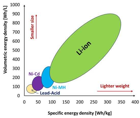
Lithium-ion batteries are one of the most popular types of rechargeable batteries available on the market for use in automotive applications due to the advantages they possess. They have one of the highest specific energies (150–350 Wh/kg) and energy densities (100–800 Wh/L) of any battery technology, as shown in Figure 1, a high open-circuit voltage (they can deliver up to 3.6 V, which is three times higher than technologies like NiCd and NiMH), a low self-discharge rate of about 1.5–2% per month, no memory effect, which is an advantage over NiCd and NiMH, both of which display this effect, and also exhibit a slow loss of charge when not in use [19][20]. They do not contain toxic cadmium, which makes them easier to dispose of than Ni-Cd batteries. Despite their technological promise, Li-ion batteries have a number of flaws, most notably in terms of safety. Li-ion batteries tend to overheat and are susceptible to damage at high voltages. Thermal runaway and combustion can occur in some cases. For these reasons, Lithium-ion batteries require safety mechanisms to limit voltage and internal pressure, which can increase their weight and, in some cases, limit their performance. They too are subject to aging with loss of capacity. Often, if not used carefully, they fail after a few years. Another barrier to widespread adoption is their high cost, which is approximately 40% higher than that of Ni-Cd [20].
Figure 1. Specific energy density and volumetric energy density of various battery types.
2.2. Supercapacitors
SCs, also called ultracapacitors (UCs), are energy storage devices operating with a behavior that fits between that of batteries and that of conventional capacitors. Supercapacitors can be classified into three main categories that consider the cell configuration, the charge storage mechanism, and the electrode and electrolyte materials: electric double-layer capacitors (EDLCs), pseudocapacitors (PCs), and hybrid supercapacitors (HSCs) [21]. They can store more energy than capacitors and provide more power than batteries (their specific power is between 2 and 10 kW/kg and power densities are in the range of 40–120 kW/L). These characteristics, along with their exceptionally high cyclability (typically higher than 500,000 cycles, which gives them a long life) and long-term stability, make SCs appealing energy storage devices [22]. SCs are required to have a high working voltage, large capacitance, and low resistance for use in pulse power applications. However, the working voltage of existing supercapacitors is typically less than 3.5 V. This necessitates that they are stacked together in series to increase the voltage, but this inevitably reduces the total capacitance of the system and increases the internal resistances, which account for more power losses [23]. The capacitance and internal resistance of supercapacitors could be enhanced by connecting them in parallel [11]. Supercapacitors also have very short charge/discharge times, usually between a few seconds and minutes, and have efficiencies between 90 and 94%.
2.3. Flywheels
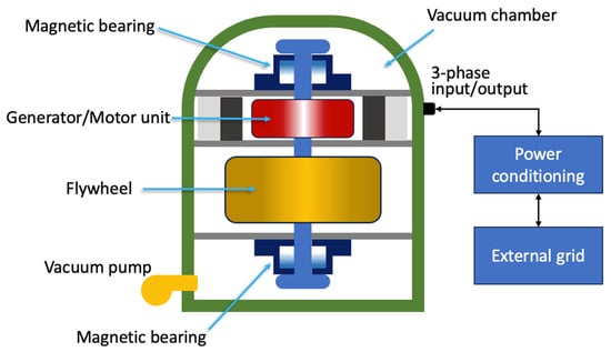
Flywheels are systems capable of storing energy in rotational kinetic form [24]. A flywheel energy storage system (FESS) is shown in Figure 2 and is made up of five primary components: a flywheel (rotating disc), a group of bearings, a reversible electrical motor/generator, a power electronic unit, and a vacuum chamber [25].
Figure 2. Schematic representation of an FESS.
2.4. Hydrogen Tank Storage
The notion of using hydrogen as a raw material to power future cars has recently attracted attention due to its abundance, clean nature, and high energy density of 120 MJ/kg, which is almost three times that of diesel or gasoline. While battery electric vehicles (BEVs) have grown in popularity and sales globally over the last decade, the adoption of hydrogen vehicles has been gradual, with one of the main reasons being difficulties in the onboard storage of the flammable hydrogen [26]. Compressed hydrogen storage presents itself as the most promising on-board storage solution because of its superior performance and convenience. It entails the storage of gaseous hydrogen in high-pressure tanks which include five standard types: Type I, II, III, IV, and V. This classification depends on the weight and low-cost tank material that can hold out against the severe pressure requirements, the material’s capacitance to withstand hydrogen diffusion, and the possible damage caused by the stored hydrogen.
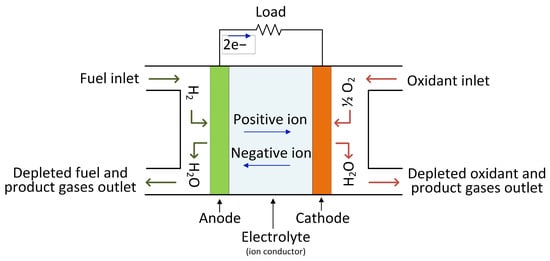
The hydrogen stored in the tanks is then fed into a fuel cell (FC), which generates low-voltage DC electrical energy that may be utilized to power AC electrical motors in cars via an appropriate high step-up DC–AC power electronic converter. A fuel cell does not require any mechanical or heat processes, and only air (oxygen) is necessary to start the operation. Figure 3 depicts the fuel cell’s operating principle.
Figure 3. The operational principle of a fuel cell.
2.5. Compressed Air Energy Storage System
CAES has previously demonstrated enormous potential in stationary energy storage applications, but its application in sustainable mobility is being investigated as a potential game-changer. A compressed-air-powered vehicle uses compressed air stored in a tank to operate. It drives the piston by expanding air rather than combining air with fuel and pushing the piston with hot expanding gases, as in traditional ICE.
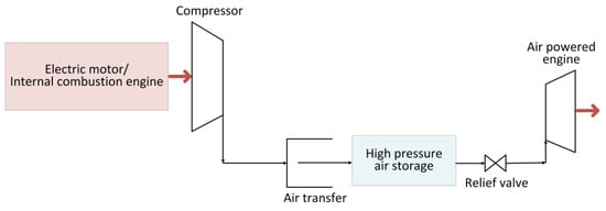
Figure 4 depicts a schematic of the air-powered vehicle’s power train. It is primarily made up of a tank where the air is stored at high-pressure by means of a compressor, and an air-powered engine. Typically, the high pressure of the tank is reduced to the operating pressure needed by the engine with a relief valve. Within the air engine, the compressed air that is injected into it expands to perform mechanical work at the shaft’s output. There are three types of air-to-mechanical-energy conversion devices: air motors, reciprocating piston-type air engines, and rotating air piston engines. There are several varieties of air motors on the market today that can be utilized for a variety of applications; however, scroll and rotary vane-type air motors are most commonly employed in automotive applications [27].
Figure 4. Schematic of compressed-air-powered vehicle.
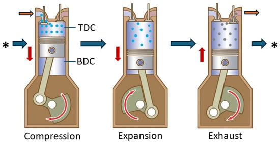
The reciprocating piston-type air engine is the most popular way to extract mechanical energy from compressed air. The engine is similar to a traditional ICE, with some variations in the air injection method, timing management, and the absence of the spark plug/fuel injector. The engine’s operational cycle consists of two strokes: expansion and exhaust. When the piston reaches the Top Dead Centre (TDC), compressed air is pumped into the cylinder via the intake valve, pushing the piston towards the Bottom Dead Centre (BDC), as illustrated in Figure 5. The air inside the piston expands as it travels, producing work transmitted to the shaft through a crank connecting rod. On the return stroke, the exhaust valve opens, causing the piston to move from BDC to TDC and expel air. The exhaust air has a lower pressure and temperature than the incoming air [28].
Figure 5. Working principle of reciprocating piston compressed-air engine. The red arrows show the moving direction of the piston. The orange arrows show the inlet/outlet where the air is entering/flowing out from the cylinder, while the blue arrows indicate the cycling sequence of the engine.
3. Power Electronic System Models for Energy Storage Systems
3.1. Batteries
Battery modeling is a very complex and challenging process. The models are needed to build the battery management systems that are required to monitor and maximize battery performance parameters like its state of charge (SoC), state of health (SoH), temperature, terminal voltage, etc. [29]. In the literature, depending on the phenomena to be studied, batteries are modeled in an abstract form with different types of models: empirical (or analytical) ones, which describe the behavior in mathematical form, electrochemical ones and electric circuits equivalent to lumped parameters. Equivalent electrical circuits are the models preferred by electronic designers when developing energy management control systems and BMS. This is because equivalent circuits are simple with linear structures and include a limited number of parameters, such as capacitances and resistances. The parameters are typically derived from experimental data and the circuits are designed to describe the dynamic characteristics of the batteries with good accuracy. This type of modeling can be applied to different types of batteries and allows you to free yourself from the specific chemistry of the battery [30]. The lumped parameters are extracted with measurement under different operating conditions such as temperature, current rate and direction, state of charge, and aging.
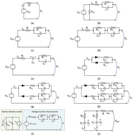
For power electronic simulations, equivalent circuit models are mainly used, and several models have been proposed by different researchers for this purpose. Some of the models are shown in Figure 6.
Figure 6. Battery equivalent circuit models: (a) zero-time-constant model [31]; (b) first-order model with self-discharge effect [32]; (c) simplified first-order model [33][34]; (d) second-order model [35]; (e) first-order PNGV model [36]; (f) modified Rint model with path selection [30]; (g) first-order Thevenin model with path selection [30]; (h) second-order model with path selection [30]; (i) runtime-based model [37][38]; (j) NREL RC battery model [39].
3.2. Supercapacitors
Given the increasing use of supercapacitors in electric mobility, the terminal modeling describing their dynamic behavior is essential. This model could be used for their performance evaluation, condition monitoring, estimations of internal energy loss, estimations of SoC/SoH, and efficiency determination. All these aspects are essential in the design of an intelligent energy management system [40].
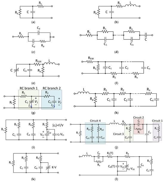
For the design and control of power electronic systems, as well as real-time energy management simulations, equivalent circuit models are of interest to the design engineer. These models mimic the electrical dynamic behavior of the SCs (voltage–current characteristics) by using parameterized RC networks. These are simple and easy to implement since they are based on ordinary differential equations (ODE). The most-used SC equivalent circuit models that can be found in the literature are shown in Figure 7.
Figure 7. SC equivalent circuit models: (a) classical equivalent circuit model (CECM) [41]; (b) first-order model [42][43]; (c) SC model using a Debye polarization [44]; (d) integer-order dynamic electrical circuit model [45]; (e) modified CECM [43]; (f) ladder circuit model [46]; (g) two-branch model [47]; (h) transmission line model [48]; (i) Zubieta Model [49]; (j) Rafik model [50]; (k) Faranda model [51]; (l) high-frequency model considering the temperature-dependency.
4. Hybrid Energy Storage Systems Applied to E-Mobility
4.1. Battery and Ultracapacitor Hybrid Systems
A battery-only storage system for electric vehicles and electric traction may be unable to provide the necessary power when demand is at its peak, as well as cope with the transient load variations in these moving systems. In such cases, the battery would need to be oversized to provide the extra power required to overcome these constraints, increasing the weight, volume, and cost, as well as the number and depth of charge/discharge cycles. All these factors contribute to battery longevity concerns [52]. Therefore, the hybridization of energy storage systems using supercapacitors and batteries in electric mobility systems offers several advantages, such as a peak power reduction and reduced battery degradation (lower stress), and hence an improved lifetime time and state of health of the battery [53].
Several hybrid battery–SC energy storage topologies have been proposed by different researchers for coupling these storage systems to the DC link through the use of bidirectional DC–DC converters. Some of the most used ones are shown in Figure 8 [21][52][53].
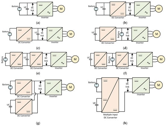
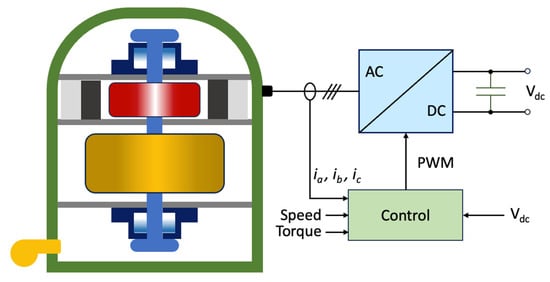
Figure 8. (a) passive parallel [29]; (b) parallel semi-active topology [54]; (c) battery–UC semi-active [54]; (d) UC–battery semi-active [54]; (e) cascaded battery–UC topology [55]; (f) cascaded UC–battery topology [55]; (g) multiple parallel-connected hybrid topology [55]; (h) multiple input converter topology [55].
4.2. Battery–Flywheel Hybrid System
The functioning principle of a flywheel-based energy storage system has been discussed in the previous sections. They have a very long rated life (typically about 20 years) and can deliver/absorb large amounts of power within a very short time.
The hybridization of flywheel storage systems with other storage systems, like batteries or supercapacitors, can be achieved using the same topologies that are presented in Figure 8. However, to interconnect the flywheel to the DC-bus, a bidirectional, three-phase rectifier/inverter will have to be linked to the flywheel, as shown in Figure 9. Whenever there is an excess of energy to be stored in the flywheel, especially during regenerative braking conditions, the flywheel electric machine acts as a motor and the power electronic converter acts as an inverter to permit an increase in the speed of the flywheel disk to allow for rotational mechanical energy to be stored. In the reverse process, when the flywheel has to provide the stored energy, the electric machine acts as a generator, and the power electronic converter acts as a rectifier to convert the three-phase generated AC voltage into a DC voltage [56].
Figure 9. Flywheel-based hybrid energy storage system.
References
- Yu, X.; Jin, Y.; Liu, H.; Rai, A.; Kostin, M.; Chantzis, D.; Politis, D.J.; Wang, L. A Review of Renewable Energy and Storage Technologies for Automotive Applications. Int. J. Automot. Manuf. Mater. 2022, 1, 10.
- Chang, L.; Zhang, W.; Xu, S.; Spence, K. Review on Distributed Energy Storage Systems for Utility Applications. CPSS Trans. Power Electron. Appl. 2017, 2, 267–276.
- Habib, A.; Hossain, S. Electric Vehicle Storage Energy System and Single Charge Balancing Circuit: Preview. Authorea 2023.
- Odero, H.Z.; Wekesa, C.W.; Irungu, G.K. Comprehensive Review of Energy Storage Technologies: Types, Applications, Optimal Sizing and Siting in Power Systems. In Proceedings of the 2022 IEEE PES/IAS PowerAfrica, Kigali, Rwanda, 22–26 August 2022; IEEE: Piscataway, NJ, USA, 2022; pp. 1–5.
- Kawakami, N.; Iijima, Y.; Li, H.; Ota, S. High Efficiency Power Converters for Battery Energy Storage Systems. In Proceedings of the 2014 International Power Electronics Conference (IPEC-Hiroshima 2014—ECCE ASIA), Hiroshima, Japan, 18–21 May 2014; IEEE: Piscataway, NJ, USA, 2014; pp. 2095–2099.
- Li, Z.; Khajepour, A.; Song, J. A Comprehensive Review of the Key Technologies for Pure Electric Vehicles. Energy 2019, 182, 824–839.
- Yang, C.; Tong, Y.; Yang, Z.; Xiao, H.; Qi, H.; Chen, F. High-Performance Aqueous Zinc-Ion Battery Based on Laser-Induced Graphene. Nanomanuf. Metrol. 2023, 6, 16.
- Grignon, E.; Battaglia, A.M.; Schon, T.B.; Seferos, D.S. Aqueous Zinc Batteries: Design Principles toward Organic Cathodes for Grid Applications. iScience 2022, 25, 104204.
- Nie, C.; Wang, G.; Wang, D.; Wang, M.; Gao, X.; Bai, Z.; Wang, N.; Yang, J.; Xing, Z.; Dou, S. Recent Progress on Zn Anodes for Advanced Aqueous Zinc-Ion Batteries. Adv. Energy Mater. 2023, 13, 2300606.
- Oliveira Farias, H.E.; Neves Canha, L. Battery Energy Storage Systems (BESS) Overview of Key Market Technologies. In Proceedings of the 2018 IEEE PES Transmission & Distribution Conference and Exhibition—Latin America (T&D-LA), Lima, Peru, 18–21 September 2018; IEEE: Piscataway, NJ, USA, 2018; pp. 1–5.
- Ogunniyi, E.O.; Pienaar, H. Overview of Battery Energy Storage System Advancement for Renewable (Photovoltaic) Energy Applications. In Proceedings of the 2017 International Conference on the Domestic Use of Energy (DUE), Cape Town, South Africa, 4–5 April 2017; IEEE: Piscataway, NJ, USA, 2017; pp. 233–239.
- EUROBAT Lithium-Based. Available online: https://www.eurobat.org/about-secondary-batteries/battery-technologies/lithium-based/ (accessed on 23 September 2023).
- BU-203; Nickel-Based Batteries. Battery University: Richmond, BC, Canada, 2021.
- Revankar, S.T. Chemical Energy Storage. In Storage and Hybridization of Nuclear Energy; Elsevier: Amsterdam, The Netherlands, 2019; pp. 177–227.
- Kurzweil, P.; Garche, J. Overview of Batteries for Future Automobiles. In Lead-Acid Batteries for Future Automobiles; Elsevier: Amsterdam, The Netherlands, 2017; pp. 27–96.
- Abdin, Z.; Khalilpour, K.R. Single and Polystorage Technologies for Renewable-Based Hybrid Energy Systems. In Polygeneration with Polystorage for Chemical and Energy Hubs; Elsevier: Amsterdam, The Netherlands, 2019; pp. 77–131.
- Thomas, B. Reddy Chapter 31: NICKEL-ZINC BATTERIES. Available online: https://www.globalspec.com/reference/67819/203279/chapter-31-nickel-zinc-batteries (accessed on 25 December 2023).
- Sundén, B. Battery Technologies. In Hydrogen, Batteries and Fuel Cells; Elsevier: Amsterdam, The Netherlands, 2019; pp. 57–79.
- Qiao, H.; Wei, Q. Functional Nanofibers in Lithium-Ion Batteries. In Functional Nanofibers and Their Applications; Elsevier: Amsterdam, The Netherlands, 2012; pp. 197–208.
- Clean Energy Lithium-Ion Battery. Available online: https://www.cei.washington.edu/research/energy-storage/lithium-ion-battery/ (accessed on 25 December 2023).
- Andreev, M.K. An Overview of Supercapacitors as New Power Sources in Hybrid Energy Storage Systems for Electric Vehicles. In Proceedings of the 2020 XI National Conference with International Participation (ELECTRONICA), Sofia, Bulgaria, 23–24 July 2020; IEEE: Piscataway, NJ, USA, 2020; pp. 1–4.
- Castro-Gutiérrez, J.; Celzard, A.; Fierro, V. Energy Storage in Supercapacitors: Focus on Tannin-Derived Carbon Electrodes. Front. Mater. 2020, 7, 217.
- Zhou, X.; Lin, Y.; Ma, Y. The Overview of Energy Storage Technology. In Proceedings of the 2015 IEEE International Conference on Mechatronics and Automation (ICMA), Beijing, China, 2–5 August 2015; IEEE: Piscataway, NJ, USA, 2015; pp. 43–48.
- Timothy, A.; Natalie, R.S.; Zhiwei, M. Thermal, Mechanical, and Hybrid Chemical Energy Storage Systems; Brun, K., Allison, T., Dennis, R., Eds.; Elsevier: Amsterdam, The Netherlands, 2021; ISBN 9780128198926.
- Luo, X.; Wang, J.; Dooner, M.; Clarke, J. Overview of Current Development in Electrical Energy Storage Technologies and the Application Potential in Power System Operation. Appl. Energy 2015, 137, 511–536.
- Cheng, Q.; Zhang, R.; Shi, Z.; Lin, J. Review of Common Hydrogen Storage Tanks and Current Manufacturing Methods for Aluminium Alloy Tank Liners. Int. J. Lightweight Mater. Manuf. 2024, 7, 269–284.
- Marvania, D.; Subudhi, S. A Comprehensive Review on Compressed Air Powered Engine. Renew. Sustain. Energy Rev. 2017, 70, 1119–1130.
- Fang, Y.; Lu, Y.; Roskilly, A.P.; Yu, X. A Review of Compressed Air Energy Systems in Vehicle Transport. Energy Strategy Rev. 2021, 33, 100583.
- Liu, J.; Dong, Z.; Jin, T.; Liu, L. Recent Advance of Hybrid Energy Storage Systems for Electrified Vehicles. In Proceedings of the 2018 14th IEEE/ASME International Conference on Mechatronic and Embedded Systems and Applications (MESA), Oulu, Finland, 2–4 July 2018; IEEE: Piscataway, NJ, USA, 2018; pp. 1–2.
- Roiu, D.; Primon, A.; Rossella, M.; Ornato, M. 12V Battery Modeling: Model Development, Simulation and Validation. In Proceedings of the 2017 International Conference of Electrical and Electronic Technologies for Automotive, Turin, Italy, 15–16 June 2017; IEEE: Piscataway, NJ, USA, 2017; pp. 1–5.
- Arianto, S.; Yunaningsih, R.Y.; Astuti, E.T.; Hafiz, S. Development of Single Cell Lithium Ion Battery Model Using Scilab/Xcos. In Proceedings of the International Symposium on Frontier of Applied Physics (ISFAP) 2015, Bandung, Indonesia, 5–7 October 2015.
- Saidani, F.; Hutter, F.X.; Scurtu, R.-G.; Braunwarth, W.; Burghartz, J.N. Lithium-Ion Battery Models: A Comparative Study and a Model-Based Powerline Communication. Adv. Radio Sci. 2017, 15, 83–91.
- Kim, Y.-H.; Ha, H. -D. Design of Interface Circuits with Electrical Battery Models. IEEE Trans. Ind. Electron. 1997, 44, 81–86.
- Lee, S.; Kim, J.; Lee, J.; Cho, B.H. State-of-Charge and Capacity Estimation of Lithium-Ion Battery Using a New Open-Circuit Voltage versus State-of-Charge. J. Power Sources 2008, 185, 1367–1373.
- Tjandra, R.; Thanagasundram, S.; Tseng, K.J.; Jossen, A. Improved Lithium-Ion Battery Model with Hysteresis Effect. In Proceedings of the 2014 IEEE Transportation Electrification Conference and Expo (ITEC), Dearborn, MI, USA, 15–18 June 2014; IEEE: Piscataway, NJ, USA, 2014; pp. 1–8.
- Johnson, V.H. Battery Performance Models in ADVISOR. J. Power Sources 2002, 110, 321–329.
- Chen, M.; Rincon-Mora, G.A. Accurate Electrical Battery Model Capable of Predicting Runtime and I-V Performance. IEEE Trans. Energy Convers. 2006, 21, 504–511.
- Knauff, M.; McLaughlin, J.; Dafis, C.; Niebur, D.; Singh, P.; Kwatny, H.; Nwankpa, C. Simulink Model of a Lithium-Ion Battery for the Hybrid Power System Testbed. In Proceedings of the ASNE Intelligent Ships Symposium, Arlington, VA, USA, 21–23 May 2007; p. 8.
- Saldaña, G.; San Martín, J.I.; Zamora, I.; Asensio, F.J.; Oñederra, O. Analysis of the Current Electric Battery Models for Electric Vehicle Simulation. Energies 2019, 12, 2750.
- Niu, R.; Yang, H. Modeling and Identification of Electric Double-Layer Supercapacitors. In Proceedings of the 2011 IEEE International Conference on Robotics and Automation, Shanghai, China, 9–13 May 2011; IEEE: Piscataway, NJ, USA, May 2011; pp. 1–4.
- Cahela, D.R.; Tatarchuk, B.J. Overview of Electrochemical Double Layer Capacitors. In Proceedings of the IECON’97 23rd International Conference on Industrial Electronics, Control, and Instrumentation (Cat. No.97CH36066), New Orleans, LA, USA, 14 November 1997; IEEE: Piscataway, NJ, USA, 1997; pp. 1068–1073.
- Helseth, L.E. Modelling Supercapacitors Using a Dynamic Equivalent Circuit with a Distribution of Relaxation Times. J. Energy Storage 2019, 25, 100912.
- Cultura, A.B.; Salameh, Z.M. Modeling, Evaluation and Simulation of a Supercapacitor Module for Energy Storage Application. In Proceedings of the International Conference on Computer Information Systems and Industrial Applications, Bangkok, Thailand, 28–29 June 2015.
- Nelms, R.M.; Cahela, D.R.; Tatarchuk, B.J. Using a Debye Polarization Cell to Predict Double-Layer Capacitor Performance. IEEE Trans. Ind. Appl. 2001, 37, 4–9.
- Zhang, L.; Wang, Z.; Hu, X.; Sun, F.; Dorrell, D.G. A Comparative Study of Equivalent Circuit Models of Ultracapacitors for Electric Vehicles. J. Power Sources 2015, 274, 899–906.
- Nelms, R.M.; Cahela, D.R.; Tatarchuk, B.J. Modeling Double-Layer Capacitor Behavior Using Ladder Circuits. IEEE Trans. Aerosp. Electron. Syst. 2003, 39, 430–438.
- Cabrane, Z.; Ouassaid, M.; Maaroufi, M. Analysis and Evaluation of Battery-Supercapacitor Hybrid Energy Storage System for Photovoltaic Installation. Int. J. Hydrogen Energy 2016, 41, 20897–20907.
- Yang, H. Evaluation of Cell Balancing Circuits for Supercapacitor-Based Energy Storage Systems. In Proceedings of the 2019 IEEE Transportation Electrification Conference and Expo (ITEC), Detroit, MI, USA, 19–21 June 2019; IEEE: Piscataway, NJ, USA, 2019; pp. 1–5.
- Zubieta, L.; Bonert, R. Characterization of Double-Layer Capacitors for Power Electronics Applications. IEEE Trans. Ind. Appl. 2000, 36, 199–205.
- Rafik, F.; Gualous, H.; Gallay, R.; Crausaz, A.; Berthon, A. Frequency, Thermal and Voltage Supercapacitor Characterization and Modeling. J. Power Sources 2007, 165, 928–934.
- Faranda, R.; Gallina, M.; Son, D.T. A New Simplified Model of Double-Layer Capacitors. In Proceedings of the 2007 International Conference on Clean Electrical Power, Capri, Italy, 21–23 May 2007; IEEE: Piscataway, NJ, USA, 2007; pp. 706–710.
- Emadi, A. Advanced Electric Drive Vehicles, 1st ed.; Emadi, A., Ed.; CRC Press: Boca Raton, FL, USA, 2014; ISBN 9781315215570.
- Sankarkumar, R.S.; Natarajan, R. Energy Management Techniques and Topologies Suitable for Hybrid Energy Storage System Powered Electric Vehicles: An Overview. Int. Trans. Electr. Energy Syst. 2021, 31, e12819.
- Zimmermann, T.; Keil, P.; Hofmann, M.; Horsche, M.F.; Pichlmaier, S.; Jossen, A. Review of System Topologies for Hybrid Electrical Energy Storage Systems. J Energy Storage 2016, 8, 78–90.
- Xiang, C.; Wang, Y.; Hu, S.; Wang, W. A New Topology and Control Strategy for a Hybrid Battery-Ultracapacitor Energy Storage System. Energies 2014, 7, 2874–2896.
- Jaafar, A.; Akli, C.R.; Sareni, B.; Roboam, X.; Jeunesse, A. Sizing and Energy Management of a Hybrid Locomotive Based on Flywheel and Accumulators. IEEE Trans. Veh. Technol. 2009, 58, 3947–3958.
More
Information
Subjects:
Energy & Fuels
Contributors
MDPI registered users' name will be linked to their SciProfiles pages. To register with us, please refer to https://encyclopedia.pub/register
:
View Times:
1.1K
Revisions:
3 times
(View History)
Update Date:
11 Mar 2024
Table of Contents


Notice
You are not a member of the advisory board for this topic. If you want to update advisory board member profile, please contact office@encyclopedia.pub.
OK
Confirm
Only members of the Encyclopedia advisory board for this topic are allowed to note entries. Would you like to become an advisory board member of the Encyclopedia?
Yes
No
${ textCharacter }/${ maxCharacter }
Submit
Cancel
Back
Comments
${ item }
|
${ item.createdUser.fullName }
${ item.createdAt }
${ item.vote }
${ item.reply }
Delete
${ reply.createdUser.fullName }
${ reply.createdAt }
${ reply.vote }
Delete
There is no reply to this comment~
${ item.replyTextCharacter }/${ item.replyMaxCharacter }
Submit
Cancel
More
No more~
There is no comment~
${ textCharacter }/${ maxCharacter }
Submit
Cancel
${ selectedItem.replyTextCharacter }/${ selectedItem.replyMaxCharacter }
Submit
Cancel
Confirm
Are you sure to Delete?
Yes
No