Hydrogen energy is regarded as an ideal solution for addressing climate change issues and an indispensable part of future integrated energy systems. The electrolyzer (EL) is the key equipment and is the interface between electrical energy and hydrogen energy in the water electrolysis (WE) process.
1. Introduction
The future energy system demands high stability, high efficiency, and carbon neutrality
[1][2][3][4]. Hydrogen energy has gained widespread attention worldwide due to its rich sources, its ecological friendliness, its high calorific value, its diverse storage and transportation methods, and its diverse application scenarios. As a zero-carbon energy carrier, hydrogen energy plays an increasingly important role in addressing the problem of climate change
[5]. According to the production methods, the hydrogen energy is classified mainly as grey hydrogen, blue hydrogen, and green hydrogen. The hydrogen energy produced through the conversion reaction of fossil fuels is called grey hydrogen due to the production of certain carbon emissions during the process; the hydrogen energy obtained by extracting carbon using technologies such as carbon capture and carbon sequestration (CCUS) based on grey hydrogen is called blue hydrogen; and hydrogen production through electrolysis of water using renewable energy sources such as photovoltaic and wind power is known as green hydrogen, which produces almost no greenhouse gas during the process
[6]. Green hydrogen is the most ideal form for hydrogen energy use, but because of its high technical threshold and cost, further development is needed to achieve large-scale applications. Blue hydrogen, as a transitional technological means, can accelerate the development of a green hydrogen society. Due to its low production cost and mature technology, grey hydrogen is still the most common hydrogen production method at present
[7].
For national or regional entities, the reduction in carbon emissions, the assurance of energy security, and the achievement of economic growth are the main driving forces for the development of hydrogen energy. Many countries have provided official policy support. For example, China positions hydrogen energy as an important component of the future national energy system and a crucial carrier for energy terminals to achieve a green and low carbon energy transformation
[8]. The United States regards hydrogen energy as a strategic reserve technology and maintains competitiveness through continuous technological research and development and the creation of centralised fuel cell (FC) demonstration applications in California
[9]. European countries view hydrogen energy as an important carrier for deep decarbonisation and the achievement of clean energy transformation. In addition, they are continually expanding the application of clean hydrogen energy in industries, construction, and other fields to accelerate the reduction in carbon emissions
[10][11][12][13]. The main driving force for Japan’s development of hydrogen energy is to achieve a diversified energy supply and ensure energy security
[14]. Based on energy security and low-carbon development, South Korea plans to make hydrogen energy the third largest industry with global strategic competitive advantages after displays and semiconductors and promote economic growth through the global output of FC technology
[15]. Traditional energy-exporting countries such as Australia, Russia, and Saudi Arabia hope to achieve economic growth through hydrogen energy exports
[16][17].
Table 1 summarises the policy documents of some countries for the development of hydrogen energy.
Table 1. Policies on hydrogen energy.
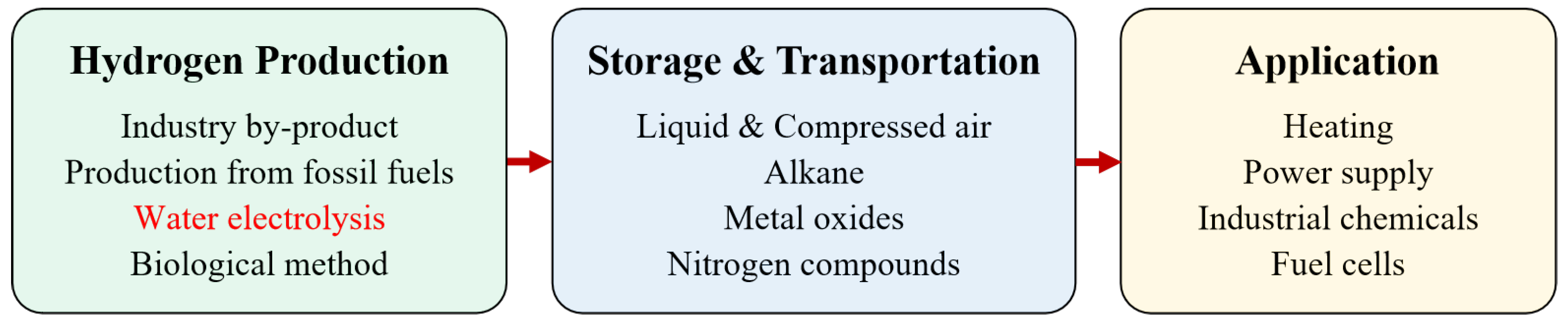
The hydrogen energy industry chain covers multiple aspects of industry and civilization
[18], as presented in
Figure 1. Downstream of the industrial chain is the field of application, including hydrogen FC transportation, industry, energy storage, and building heating–power cogeneration. The middle layer includes hydrogen storage and transportation. Hydrogen can be stored as high-pressure gaseous, low-temperature liquid, organic liquid, and solid materials. Among them, gaseous hydrogen is currently the main storage method and can be transported using long tube trailers for short-distance and small-scale scenarios, and pipeline transportation, which has a large volume and low operation cost, but the construction investment is large.
Figure 1. Industrial chain of hydrogen energy.
The upstream chain of the hydrogen energy industry chain mainly includes fossil energy reforming, industrial by-product gas, water electrolysis (WE), and other technologies in the experimental stage. Among them, fossil energy reforming is currently the most popular method for hydrogen production, with the lowest cost but emitting a significant amount of carbon dioxide; hydrogen production from industrial by-product gas cannot be applied as a centralised source of hydrogen supply. The process of WE has no carbon emissions, currently accounting for a relatively low proportion, as the cost is higher than the other methods
[18]. However, WE becomes increasingly attractive, as the process can effectively absorb fluctuating power electricity such as wind and photovoltaic power.
The electrolyzer (EL) is the key equipment and is the interface between electrical energy and hydrogen energy in the WE process. Most of the currently published reviews related to EL focus mainly on the principle of the electrolytic reaction and the effect of catalysts in the chemical domain, e.g.,
[19][20][21][22][23][24]. Few papers focus on the coupling of the electrical and chemical domains in the EL and analyse the power supply of the electrolytic cell from the perspective of power electronic topology and integrated energy system control. Some conventional DC/DC converter topologies are summarised in
[25][26], yet not all of them are specially designed for the EL. Although the voltage step-down ratio and the output current ripple are compared with respect to the duty cycle, all converters are controlled by classical pulse width modulation (PWM). The comparison results in
[25][26] are not applicable to other widely applied topologies, such as resonant converters, which are usually regulated by a soft-switching control algorithm. Furthermore, these reviews focus only on the control of the power supply itself, ignoring the influence of other components in the EL and the coordinated operation of the whole integrated energy system. The characteristics of other reviews on ELs are summarised in
Table 2. The pros and cons of the review are highlighted with bullet point symbol and lozenge symbol, respectively.
Table 2. Characteristics of other related reviews on ELs.
|
References
|
Characteristics
|
|
[19][20][21][22][23][24]
|
-
Focus mainly on the chemical domain performances and modeling of specific WE methods, such as the principle of electrolytic reaction and the effect of catalyst.
-
The challenges related to electrode, catalyst, and membrane materials are addressed.
-
◇
-
Power supplies are simulated using ideal current sources.
-
◇
-
Performances and coordinated control of the power supply are ignored.
|
|
[25][26]
|
-
◇
-
The scope of the converter topologies reviewed is limited to the classical PWM controlled types.
-
◇
-
Many novel topologies that have been widely applied now, such as soft-switching resonant converters, are not included in the discussion.
-
◇
-
Control of the power supply itself is presented, but the influence of other components in the EL and the coordinated operation of the entire integrated energy system are not reviewed.
|
2. Water Electrolysis Methods
Currently, there are four main WE methods, including alkaline (ALK) WE, proton exchange membrane (PEM) WE, solid oxide (SOE) WE, and anion exchange membrane (AEM) WE
[19][20]. Among them, ALK WE was the first industrialised, with the most mature technology and industry chain. PEM WE technology has developed gradually in recent years, and its market share has been continuously increasing. Both the AEM WE and SOE WE technologies are still in the laboratory stage, and there is still a certain distance from commercialisation
[27].
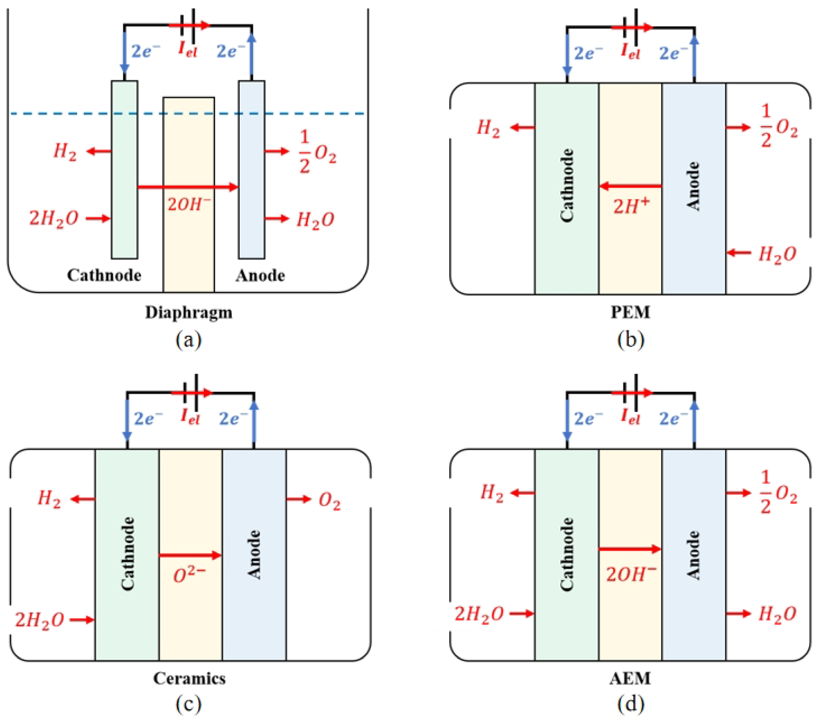
The principle of ALK WE is presented in
Figure 2a. The two electrodes are separated by an airtight diaphragm. To maximise ion conductivity, both the electrode and diaphragm are immersed in a high-concentration ALK liquid electrolyte, with a solute typically KOH or NaOH, and a typical operating temperature range of 70 to 90 degrees Celsius. Water molecules undergo a reduction reaction at the cathode and decompose into hydroxide and hydrogen ions. Hydrogen ions combine with electrons to generate hydrogen gas, which is discharged from the cathode. Hydroxide ions pass through the diaphragm and undergo an oxidation reaction at the anode under the action of an electric field established by the EL power supply, generating oxygen and electrons. As a result of the high concentration of gas products released from the electrode, which can reduce the electrolysis efficiency, it is necessary to use a porous structure and maximise the contact area between the electrode plate and the liquid electrolyte when designing the electrode. During operation, the temperature gradient and precipitation of gases within the electrolyte will promote the flow of electrolytes and establish convective circulation. The movement of this electrolyte helps make the concentration of chemical substances in the electrode pores more uniform, further promotes the precipitation of gas products, and improves the heat transfer rate and the heat dissipation effect of the electrolysis unit. Details about the operating principle of ALK WE can be found in
[22]. ALK WE technology is easy to deploy and apply quickly to solve the problem of renewable energy consumption in the near future
[28].
Figure 2. Scheme of the operating principle of (a) ALK WE; (b) PEM WE; (c) SOE WE; (d) AEM WE.
In the PEM WE process, as presented in
Figure 2b, the electrolyte is an airtight, thin PEM. Because of the functional groups of sulfonic acid, the PEM has a cross-linked structure and strong acid properties. These functional groups conduct proton conduction through ion-exchange mechanisms. The EL adopts a bipolar configuration, with a bipolar plate supporting the membrane electrode and the gas diffusion layer to converge the gas and conduct electrons. The membrane electrode component is composed of an electrode made of precious metals such as platinum or iridium and a PEM. During operation, water molecules undergo oxidation reactions at the anode to generate oxygen, electrons, and protons. Oxygen is precipitated at the anode, and electrons are transmitted to the cathode through an electrical circuit. Under the action of the electric field, protons circulate through the PEM to the cathode and react with electrons to synthesise hydrogen. PEM EL uses PEM as solid electrolytes instead of separators and liquid electrolytes in ALK EL and uses pure water as a raw material to avoid potential alkaline pollution and corrosion problems
[29].
The operation principle of the SOE EL and the AEM EL are presented in Figure 2c and Figure 2d, respectively. The electrolysis reaction in the SOE EL is performed at a high temperature. In comparison to the electrolysis of water at low temperatures, SOE can theoretically provide a higher energy conversion efficiency. High-temperature water vapour reacts at the cathode of SOE EL, and water molecules obtain electrons to generate hydrogen and ionise oxygen ions. Oxygen ions are directed to the anode in an electrolyte composed of conductive ceramic materials and oxidised to form oxygen. In AEM EL, water molecules participate in the reducting reaction on the cathode side to obtain electrons and generate hydroxide ions and hydrogen. After reaching the anode through AEM, hydroxide ions participate in the oxidation reaction to lose electrons and generate water and oxygen. Similar to ALK, a certain amount of alkaline solution is needed to add to the AEM electrolyte to improve efficiency.
ALK ELs are suitable for large-scale hydrogen production thanks to its mature development status and large device capacity
[30]. However, the diaphragm used in ALK EL is made of porous material, making the gas easy to penetrate and causing high electrical energy loss. Load changes can also cause an imbalance in the pressure of the electrode, increasing the risk of explosion as a result of excessive hydrogen permeation. ALK electrolytes will react with carbon dioxide in the air to form insoluble carbonates, hindering the convective transfer of products and reactants and affecting the electrolysis efficiency. The dynamic response of ALK ELs is usually in several minutes, making it difficult to cooperate with high-volatility renewable energy generation, such as wind or solar energy generation.
The PEM is thinner and has a stronger proton conductivity compared to that of the diaphragm used in the ALK EL. The internal structure of the PEM EL is more compact, which helps reduce the ohmic resistance. The hydrogen gas generated in PEM EL will not introduce alkali mist, which is beneficial for improving the quality of the hydrogen gas
[31]. More importantly, the gas permeability of PEM is low, helping to prevent the cross-permeation of hydrogen and oxygen gases, ensuring the purity of the product and the safety of the operation of the equipment
[32].
With the increase in temperature, the demand of electrolysis reaction for temperature increases, but the demand for electrical energy decreases. SOE can make full use of heat energy when operating at high temperature, thus reducing the consumption of electrical power. Therefore, the power consumption efficiency of the SOE EL is higher than that of ALK and PEM. However, the operating temperature of up to thousands of degrees Celsius also limits the development of the SOE hydrogen production scenario. In addition, the start–stop dynamic response time of SOE is very slow and is difficult to deploy in a system powered by renewable energy. At present, SOE EL products have not been commercialised.
In general, PEM EL is smaller, more compact and scalable than ALK EL, with higher current density, efficiency, hydrogen purity, faster response speed, and better compatibility with distributed energy generation such as wind and solar power
[33]. Even though SOE EL performs better in current density and power efficiency in a laboratory experiment, these advantages have not been further verified by the industry, and it takes decades for commercialisation. PEM EL is a better choice for coordination with increasingly penetrating renewable energy. Currently, the disadvantage of PEM lies in its device cost, but it is expected to be further reduced with the development of FCs as PEM EL and PEM FC share most supply chains
[21][34].
3. EL Market
The EL market today is dominated by ALK ELs and PEM ELs. Geographically, most EL manufacturers are located in western Europe, the United States, and China
[35][36].
From the perspective of the EL type, the proportion of ALK EL in 2022 was 72.1%. Although its capacity increases by 80.2% in 2023, the proportion of ALK EL decreased to 64.3% due to the higher growth rate of the PEM EL capacity (158.1%). Due to the longer development history and more mature technology of ALK EL, there are more new manufacturers in 2022 than in 2023. Relatively speaking, the technical threshold of PEM EL is relatively high, and there are few new manufacturers, but many manufacturers that master PEM technology have greatly increased their production capacity owing to the advantages of research and development, such as Plug Power, ITM Power, Ohmium, Cummins, and Siemens Energy. The technical level of PEM EL is developing rapidly in response. The annual global manufacturing capactity of ELs is expected to increase to 242 GW by 2030, and PEM EL will account for the largest market share
[35][36][37].
As presented in Figure 1, the EL is located in the upper part of the hydrogen energy industry chain, and its production capacity will be affected by the level of development in the middle and lower reaches of the industrial chain, especially the application of hydrogen energy. With the development of hydrogen energy in the automotive and chemical industries, the market demand for ELs will also continue to increase. At present, the cost of WE hydrogen production is higher than that of grey hydrogen production, and the development of ELs also depends on the strength of the policy support. The promotion of the carbon market and the further maturation of the new energy generation support facilities are conducive to the expansion of the market share of ELs. Under the guidance of zero-carbon policies, fossil energy is facing more stringent carbon emission restrictions, and EL benefits from its zero carbon emissions in the whole process, which will occupy a more important position in the global energy industry.
 +1 credit