Power converters can convert the electrical energy output by power source into specific forms required by target device. They are widely used in various fields such as electrification, transportation, and power systems, and are the core components of the systems. “Symmetry” means “the quality of being very similar or equal” or “the exact match in size and shape between two halves, parts or sides of something”. Symmetry is an important attribute of power converters. Whether it is a two-level, three-level, or multi-level converter, they all have a certain symmetry in structure, which is referred to as "Topological Symmetry of Power converters". This topological symmetry means that the voltage/current output from each phase of the converter are also symmetrical, with only a specific phase angle difference. Studying this symmetry is helpful for the design, operation analysis, and fault diagnosis of power converters.
1. Introduction
Whether it is a spacecraft, high-speed train, or modern household appliance, power converters are needed to convert the power from the supply into electric energy with a specific amplitude, frequency, and other indicators that meet the requirements for use.
Power transistor faults are mainly categorized as SC (short-circuit) and OC (open-circuit) faults. SC faults are often accompanied by overcurrent, which will trigger a circuit breaker, fuse, or other hardware-protection circuits immediately and are easy to detect. Whereas an OC fault will generally not cause the system to shutdown immediately, but degrade the system’s performance, such as by creating voltage unbalance, harmonic distortions, and system fluctuations
[1][2]. Even worse, if not dealt with in a timely manner, such OC faults may lead to cascading failures or even system crashes, causing a loss of life and property
[3]. Therefore, in recent decades, various methods for the diagnosis of OC faults in power converters have been proposed, especially for situations where reliability and safety are highly valued, such as in a traction converter
[4][5].
The method for the diagnosis of power transistor OC faults in converters can be mainly divided into three categories: hardware-based, model-based, and signal-based methods. Hardware-based methods can detect and locate faults quickly but require additional devices such as sensors or circuits, which in turn limits the application of the method
[6][7][8]. Model-based fault diagnosis methods usually establish mathematical models for power converters first and diagnose the fault by comparing the signal observed from the model with actual measured values
[9][10][11]. These methods have a short diagnosis time but require knowledge and parameters related to system structure, operation model, and other aspects. Signal-based methods usually extract features first and then use these features to train the classifier or classify them directly by comparing the characteristic value with thresholds
[3][12]. Requiring neither additional sensors nor precise models and parameters of the system, the signal-based methods have the advantage of a fast diagnostic speed and low computational complexity. This is a key step is the selection of diagnostic features. It should be pointed out that, although deep learning has developed rapidly in recent years, there are still many limitations in utilizing raw data as the input of classifiers due to the limited computing power of processors used in actual industrial scenarios
[13].
Therefore, feature extraction is the key to signal-based fault diagnosis methods, which is also the core of most research in recent years
[3][14]. If the features are well selected, good classification results can be obtained through a simple classifier; on the contrary, to achieve an equivalent performance, complex classifiers are required, and sometimes it is still difficult to obtain satisfactory results. This is because power converters often have limited information available for diagnosis, but the fault patterns are complex, making it difficult to effectively classify using a single, low dimensional feature. Taking a two-level three-phase inverter with an induction motor as an example, this is the most basic topology structure, but there are four categories and 21 types of single-transistor and double-transistor faults. In addition, the motor has a huge difference in current during the processes of starting, braking, load adjustment, acceleration, and deceleration, which can easily be confused with fault situations
[15]. The power converters usually work in a complex electric-magnetic-mechanical-thermal coupling field, with numerous influencing factors. Therefore, selecting features with high discrimination is of great significance for power converter fault diagnosis. Many features, such as the average value, absolute value, effective value, skewness, kurtosis in the time domain, and the transformed coefficients such as Fourier transform and wavelet transform in the frequency domain, have been selected as features for diagnosis and have achieved certain results
[16]. In addition, a widely adopted but not systematically studied feature is symmetry, which has achieved remarkable results in power converter fault diagnosis
[17][18].
2. Topology and Symmetry Analysis of Power Converters
2.1. Symmetry—A Common Property of Power Converters
Power conversion can usually be divided into four categories, namely rectification (AC-DC), inversion (DC-AC), chopping (DC-DC), and AC-AC conversion. As mentioned before, the power converters studied here mainly include rectifiers and inverters.
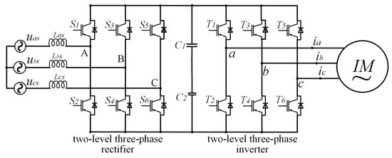
Figure 1 shows the topological structure of a variable frequency speed control system for an induction motor, which includes a rectifier and an inverter. The three-phase AC power provided by the left power supply is first converted into DC through the two-level rectifier, filtered by DC bus capacitors, and then converted into specific AC by the inverter to drive the induction motor (IM) on the right. Each phase of the power supply and IM corresponds to a leg, which is composed of two power transistors. The control system generates gate signals through control algorithms to control the conduction and shutdown of each power transistor, causing the inverter to generate a specific amplitude, frequency, and phase currents. In the healthy condition, the output three-phase currents
𝑖𝑎,
𝑖𝑏 and
𝑖𝑐 are identical sine waves with only a phase angle difference of
2𝜋/3, so they are also called “three-phase symmetrical currents”. After the three-phase symmetrical currents pass through the symmetrical three-phase stator winding, a circular rotating magnetic field is generated, which drives the motor to rotate. This concise and elegant symmetrical design reduces system complexity, and improves output performance, which is of great significance
[19].
Figure 1. A topological structure of variable frequency speed control system for induction motor, including a rectifier and an inverter.
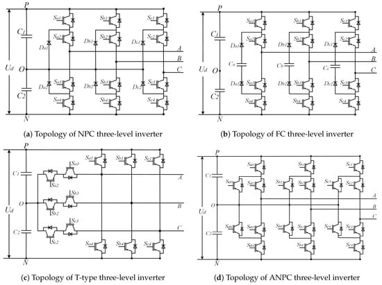
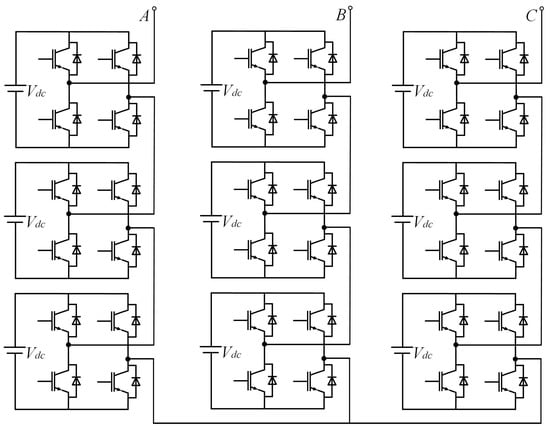
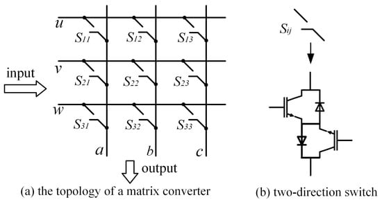
In addition to two-level converters, symmetry is commonly present in power converters, as shown in the four types of three-level inverters in Figure 2, the multi-level cascaded inverters in Figure 3, and the matrix converters in Figure 4. In Figure 1, in terms of the overall structure, the two-level three-phase rectifier and the inverter are symmetrical, except that their input and output are exactly opposite. Within the inverter and rectifier, the legs corresponding to each phase are symmetrical, and for each leg, its upper and lower halves are also symmetrical. Compared to two-level power converters, three-level converters have multiple topologies. Figure 2 shows four typical three-level inverter topologies, namely, the neutral point clamped (NPC), the flying clamped capacitor (FC), the T-type, and the active neutral point clamped (ANPC) three-level inverter. Though different from each other, the four inverters are all highly symmetrical in structure. The same applies to other multi-level power converters, which have more diverse topological structures but always share the common property—symmetry.
Figure 2. The topological structures of four typical three-level inverters.
Figure 3. A topological structure of cascaded H-bridge converter.
Figure 4. Matrix converter.
2.2. Symmetry Analysis in Different Situations—Taking a Two-Level Three-Phase Voltage-Source-Inverter as an Example
The above shows the structures of power converters under healthy conditions. When an OC fault occurs in power transistors, the symmetry in the converter tends to change. And the degree of change varies with the number and location of the faulty transistors. As the symmetry in the topological structure cannot be directly quantified and measured, electrical signals such as voltage and current in the power converters are often collected in practical applications. The information about the symmetry of power converters is often contained in these collected time series. Taking the two-level three-phase inverter in Figure 1 as an example, a detailed analysis is conducted below.
Generally, unless there is a sharp decline in system performance or a shutdown, the three-phase currents in the inverter are periodic under both healthy and faulty conditions. Assuming that at instant
t, the sampled three-phase current time series within a period is
where
L is the number of sampling points within a fundamental current period
T.
m refers to a phase in the inverter. Let
f be an abstract function for calculating the symmetry of time series,
𝑆𝑚𝑛 represents the symmetry between phase
m and phase
n, and
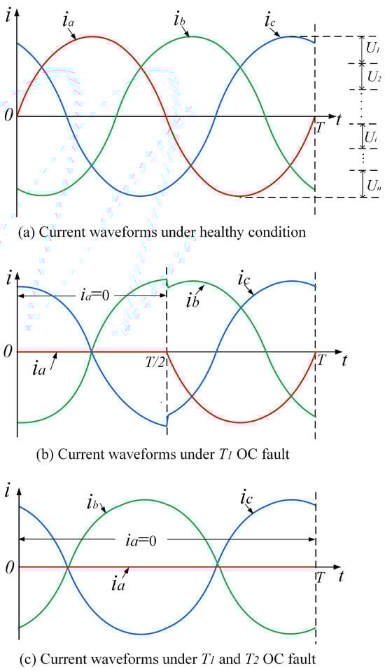
𝑆𝑚𝑛=𝑓(𝐼𝑚,𝐼𝑛).Under healthy conditions, due to the fact that 𝑖𝑎, 𝑖𝑏, and 𝑖𝑐 are symmetrical sine waves, as shown in Figure 5a, then qualitatively the below formula holds,
Figure 5. Current waveforms of the inverter in different conditions.
When an OC fault occurs in a power transistor such as
𝑇1, the current waveform will be distorted. As shown in
Figure 5b, in the later half of the period, it is
𝑇2’s turn to work and
𝑇1 should be turned off, so the
𝑇1 OC fault has no impact on the output. While in the former half of the period,
𝑇1 should have been working. But due to the OC fault, the actual output current in phase-
a is 0. The waveforms of
𝑖𝑏 and
𝑖𝑐 will also undergo distortion due to the
𝑇1 fault, but the degree of distortion is consistent and both are relatively small. Therefore,
When an OC fault occurs in a multi-transistor such as
𝑇1 and
𝑇2, phase-
a has no current in the whole period, namely
𝐼𝑎=0, as shown in
Figure 5c. According to Kirchhoff’s current law,
𝑖𝑎+𝑖𝑏+𝑖𝑐=0. Therefore,
𝐼𝑏=−𝐼𝑐. Thus, though the current in phase-
b and phase-
c have also undergone significant distortion, they are still symmetrical, with only opposite signs. And
𝐼𝑎 is always 0, without any symmetry with
𝑖𝑏 and
𝑖𝑐. And there should be
Based on the above analysis, the symmetry of phase currents in power converters varies under healthy and different fault conditions. Therefore, symmetry can be used as a feature to distinguish different faults. Specifically, as mentioned before, distance, etc., have a clear quantitative calculation formula and are all essentially a quantification of symmetry.
 +1 credit