Rigid robots have found wide-ranging applications in manufacturing automation, owing to their high loading capacity, high speed, and high precision. Nevertheless, these robots typically feature joint-based drive mechanisms, possessing limited degrees of freedom (DOF), bulky structures, and low manipulability in confined spaces. In contrast, continuum robots, drawing inspiration from biological structures, exhibit characteristics such as high compliance, lightweight designs, and high adaptability to various environments. Among them, cable-driven continuum robots (CDCRs) driven by multiple cables offer advantages like higher dynamic response compared to pneumatic systems and increased working space and higher loading capacity compared to shape memory alloy (SMA) drives. However, CDCRs also exhibit some shortcomings, including complex motion, drive redundancy, challenging modeling, and control difficulties.
1. Introduction
1.1. Origins of Continuum Robots
Rigid robots have found wide-ranging applications in manufacturing automation, owing to their high loading capacity, high speed, and high precision
[1][2][3]. However, these robots typically feature joint-based drive mechanisms with limited degrees of freedom (DOF) and bulky structures, making it difficult for them to perform tasks in narrow and cluttered workspaces, such as gastroenteric operations and cave rescue missions
[4]. To address such challenges, bio-inspired continuum robots, which have unique characteristics, such as high compliance, lightweight designs, and high adaptability to various environments, have received increasing attention in the robotics community
[5][6][7].
The concept of continuum robots dates to the 1960s
[4][8], but it was not formally introduced until 1999
[9]. Continuum robots are typically defined by their hyperflexible electromechanical structures with infinite degrees of freedom, which provide them with the ability to maneuver complex curvilinear pathways
[10]. In comparison to rigid robots, continuum robots stand out for their continuous deformation capabilities, allowing them to adapt effectively to various environmental conditions and execute corresponding tasks
[11]. For instance, the snake’s spine, capable of coiling and traveling, has inspired the creation of various continuum robots
[12]. These robots are typically defined as having much more kinematically drivable DOF than the DOF of the robot’s workspace
[13]. Additionally, nature’s examples, such as elephant trunks, octopus tentacles
[14], frog tongues
[15], and earthworms
[5], exhibit continuous muscle tissue
[16] and offer diverse functions, including expansion, coiling, grasping, and adsorption, despite the lack of rigid material support. Continuum robots, as a result, exhibit exceptional flexibility and freedom of motion. Notably, not all DOF are directly actuated
[13]. However, they are often underactuated as researchers aim to achieve the desired manipulator positions with as few drives as possible to reduce the hardware cost. As results, despite their theoretical unlimited DOF
[17], many continuum robots are often equipped with fewer drives than their DOF suggests, striving for optimal balance.
1.2. Classification of Continuum Robots
Common continuum robots can be categorized based on their driving methods into three main types: pneumatic, cable-driven, and SMA-driven.
-
Pneumatic continuum robots rely on air pressure as their driving force
[18]. They are known for their high flexibility, simple structures, smooth movement, and lightweight construction
[19]. Typically, these robots consist of multiple pneumatic chambers, with robot movement achieved by controlling changes in air pressure
[20][21]. Nevertheless, pneumatic continuum robots have limitations, including restricted precision, noise generation, and high maintenance costs.
-
SMA-driven continuum robots use shape memory alloys, special metal alloys known for their memory shape and superelasticity
[22], as their driving mechanism. They exploit the SMA’s memory shape and superelastic properties to enable bending and torsion of flexible segments, facilitating the robot’s movement and operations
[23][24]. SMA-driven continuum robots offer advantages such as simple driving devices, fast response times, and low power consumption. However, they are also susceptible to drawbacks like high material costs, low load capacity, and sensitivity to temperature and stress.
-
Cable-driven continuum robots, sometimes referred to as tendon-driven or line-driven robots, rely on flexible supporting structures (backbones) and driving cables to achieve motion by adjusting cable lengths and tension
[25][26][27]. These robots can change shapes and positions continuously, making them lightweight and intrinsically safe. They are particularly suited for more precise operations in confined spaces and exhibit smaller response lag compared to pneumatic robots
[28][29][30]. They also offer a larger working space and higher load capacity compared to SMA-driven systems. However, CDCRs face challenges such as complex motion, modeling difficulty, low control accuracy, actuation redundancy, and relatively large drive mechanisms. Consequently, the design analysis, kinematics and dynamics modelling, motion planning, and control for CDCRs have become complex interdisciplinary fields that attract growing interest among researchers.
2. CDCR Configurations and Cable Arrangements
The design of CDCRs involves a multi-faceted process, demanding a meticulous evaluation of several critical parameters. This mainly includes the robot’s length, diameter, bending radius, weight, and load capacity, as well as cable tension, diameter, material, layout, and adherence to force closure conditions
[31]. CDCRs are usually composed of a backbone, moving platform, and drive mechanism, in which the design of the backbone plays a pivotal role. The overarching aim of this process is to equip the robot with the desired level of flexibility and controllability while upholding its stability and reliability.
2.1. CDCR Configurations with Different Backbone Stuctures
2.1.1. CDCR with Sheet Type Backbone
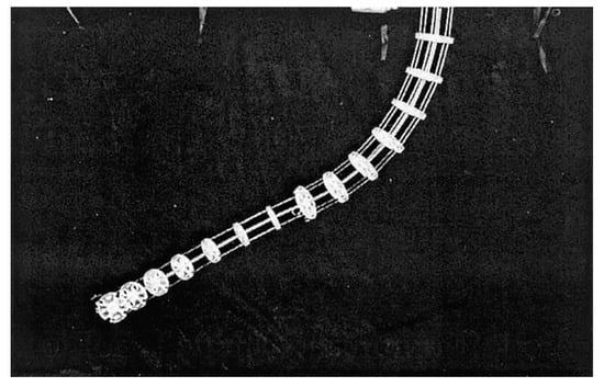
The earliest prototype of a CDCR, conceived by Walker et al. at Clemson University in 2000, serves as an exemplary illustration of a fundamental design (see
Figure 1)
[32][33]. Comprising 11 joints and propelled by just two cables, this robot featured a sheet spring steel backbone. Despite being constrained to a 1-DOF, empirical evidence demonstrated that the robot could maintain its end-effector orientation even in the presence of external forces near the base.
Figure 1. 1-DOF Clemson tentacle manipulator
[34].
2.1.2. CDCR with Rod Type Backbone
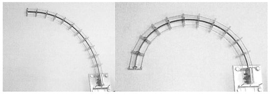
In 2001, the Clemson tentacle manipulator was enhanced
[34], featuring two independent parts with 2-DOF each (see
Figure 2). The flexible thin rod served as the backbone, and cable guides were periodically spaced along its length. Four pairs of cables traversed these guides, with two pairs terminating at the midpoint and two pairs at the end. Varying cable tension allowed torque to be applied orthogonally either at the midpoint or the end of the manipulator trunk. This classic configuration not only provided valuable foundational insights but also served as a source of inspiration for subsequent advancements in CDCRs.
Figure 2. 4-DOF Clemson tentacle manipulator
[34].
2.1.3. Modular CDCR with Rod Type Backbone
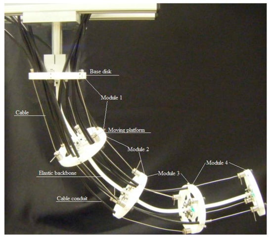
Beginning in the last decade, researchers began to focus on the development of CDCRs, with notable advancements. Between 2010 and 2014, Yang et al. at Nanyang Technological University introduced a cable-driven flexible snake-like robot prototype
[30][35][36]. This design adopts a modular approach, comprising multiple identical rod-driven joint modules in series (
Figure 3). Each module includes a base disk, three cables, an elastic backbone, and a mobile platform, resulting in a remarkable total of 8-DOF. These robots employ motors to drive the cable coils, offering exceptional versatility. However, increasing the number of active joints and the distance between arm disks introduced challenges, notably the formation of S-shaped deformations in the robot’s structure. Several factors contribute to this phenomenon, including the interaction of dead weight and external loads with cable torque and the risk of buckling deformations due to cable tension.
Figure 3. Cable-driven flexible snake-like robot prototype
[36].
2.1.4. CDCR with Notch Elastic Backbone
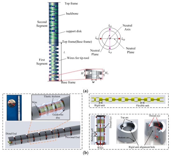
In 2013, Du et al. at Harbin Institute of Technology introduced a continuum robot featuring a novel triangular notch design for the first time
[37], depicted in
Figure 4a. In this design, a cable is driven through a two-sided symmetrical channel within a nickel-titanium tube, enabling a 1-DOF bending movement within a plane. By employing joint superposition, a 2-DOF manipulator can be realized. Recognizing the initial design’s limitations in terms of DOF, the study introduced an updated configuration in 2020
[38] with alternating orthogonal incisions, as illustrated in
Figure 4b. This revised continuum robot incorporates a notched elastic backbone (constructed from Nitinol) and a guide reel for decoupling purposes.
Figure 4. A continuum robot with a triangular notch: (
a) solid continuum arm model of two segments and connecting frame
[37]; (
b) composed model of the continuum manipulator, working schematic diagram of the continuum manipulator, the Nitinol skeleton, and structure of the guidewire disc
[38].
2.1.5. CDCR with Extensible Backbone
In 2006, NASA developed the Tendril continuum robot
[39] specifically designed for inspection operations in outer space, depicted in
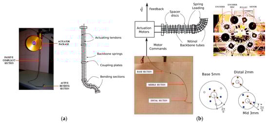
Figure 5a. This innovative robot utilizes tandem springs as its backbone to maintain a slender profile and lightweight construction. While gravity’s influence can be discounted in space, the choice of springs as the backbone introduces a pronounced coupling effect among the joints, often resulting in buckling phenomena, characterized by severe S-shaped deformation. However, in 2015, Walker et al. at Clemson University significantly improved its performance
[40][41], as illustrated in
Figure 5b.
Figure 5. Continuum robots designed for inspection operations in outer space: (
a) NASA’s Tendril continuum manipulator with its compact actuation/housing unit and schematic of the design
[40], and (
b) actuation mechanism and actuation package of the robotic arm with robotic cable developed at Clemson University, USA, along with spacer design for the base, mid, and distal continuum sections. Note the offset of adjacent sections for guiding tendons without crowding
[40]. The different colored circles represent the perforations of the different sets of cables on the arm disc.
2.1.6. CDCR with Multi-Backbone
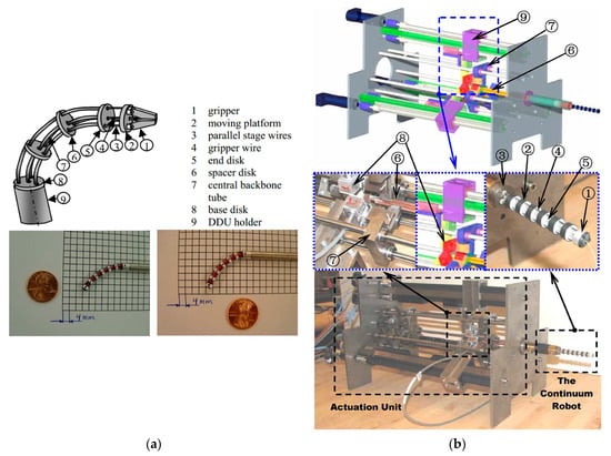
In 2004, Simaan et al. at Johns Hopkins University introduced a sophisticated system tailored for laryngeal surgery
[42]. At its core are three distal dexterity units (DDU), essentially miniature continuum robots (
Figure 6a). The DDU comprises a base disk, an end disk, a series of spacer disks, and four hyperelastic tubes, serving as the robot’s backbone. Among these tubes, one is the central main backbone, while the other three act as secondary backbones. Remarkably, these secondary backbones serve dual purposes: they provide support to prevent buckling deformations and act as driving mechanisms, eliminating the need for traditional cables. This innovative approach enables bidirectional motion through a push–pull mechanism. The robot’s primary and secondary frames are constructed from superelastic nickel–titanium tubes and offer 1-DOF. In 2008, Xu
[43] from Columbia University enhanced this concept by achieving 2-DOF through the simultaneous actuation of three secondary backbones (
Figure 6b). This improvement allowed for precise control while maintaining structural rigidity.
Figure 6. Distal dexterity units: (
a) The DDU using a multi-backbone snake-like robot with detachable parallel tip and a DDU prototype
[42], and (
b) a
∅7.5 mm continuum robot composed of an end disk, spacer disk, base disk, secondary backbone, primary backbone, actuation rods, actuation cantilever with linear ball bearings, load cells, and double-supported actuation sliders
[43].
2.1.7. Discussions on Backbone Structures
The configurations of continuum robots throughout different eras are briefly summarized in Table 1. It is realized that traditional continuum robots have typically grappled with S-shaped deformation and uncontrollable translational DOF, thereby affecting manipulator accuracy and load-bearing capacity. Furthermore, these robots tend to have limited overall DOF, resulting in a relatively small reachable and dexterous workspace, one which does not fully exploit the flexibility and compliance advantages offered by continuum robots. Presently, most continuum robots employ a straight-pull cable arrangement, wherein each cable runs parallel to the backbone. This arrangement leads to a singular position when the manipulator is not bent, offering no means to constrain the translational freedom of the arm discs.
Table 1. Summary of CDCR configurations.
| Year |
References |
DOF |
Number of Drives |
Drive Types |
Backbone |
| 2000 |
[32][33] |
1 |
2 |
Cable |
Sheet-type spring steel |
| 2001 |
[34] |
4 |
4 |
Cable |
Thin elastic rod |
| 2004 |
[42] |
2 |
3 |
Ni-Ti tube |
4 Ni-Ti tubes |
| 2006 |
[39] |
4 |
2 |
Cable |
Extensible spring steel |
| 2008 |
[43] |
2 |
3 |
Ni-Ti tube |
4 Ni-Ti tubes |
| 2010 |
[30][35][36] |
8 |
3 |
Cable |
Elastic rod |
| 2011 |
[44] |
2 |
3 |
Fiberglass |
Rod-type spring steel |
| 2012 |
[45][46] |
2 |
3 |
Fiberglass |
Rod-type spring steel |
| 2013 |
[37] |
1 |
2 |
Cable |
Notch elastic Ni-Ti backbone |
| 2015 |
[40][41] |
9 |
3 |
Cable |
Extensible concentric tubes and springs |
| 2015 |
[47][48] |
9 |
3 |
Cable |
Extensible Ni-Ti concentric tubes |
| 2020 |
[38] |
2 |
4 |
Cable |
Notch elastic Ni-Ti backbone |
| 2020 |
[49][50] |
4 |
3 |
Ni-Ti rod |
4 Ni-Ti rods |
| 2021 |
[51][52][53] |
16 |
2 and 3 |
Cable |
Notch elastic metal backbone |
2.2. CDCR Cable Arrangements
2.2.1. Cable Arrangement in Existing CDCRs
In the context of the entire CDCRs, three distinct cable arrangement methods are presented: complete penetration method, partial penetration method, and modular method.
The full penetration method penetrates all the cables through all the moving platform, but the whole arm is only 2-DOF, which is difficult to bear large loads. The partial penetration method involves routing the drive cables through each moving platform, allowing each set of drive cables to influence not only their respective joints but also all the joints they traverse. This method increases the degree of freedom of the whole arm and offers significantly improved load-bearing capacity but introduces multi-joint coupling, which elevates control complexity.
2.2.2. Force Analysis for Different Cable Arrangements
To determine the optimal method for active cable tensioning, a comparative analysis of three distinct cable arrangements was conducted: the parallel cable arrangement, slanted cable arrangement, and slanted cable arrangement with intermediary dick. Simultaneously, the factors contributing to initial manipulator drooping or singularity were also explored. The findings led to the conclusion that the slanted cable arrangement effectively mitigates the sagging of the backbone.
2.2.3. Discussions on Cable Arrangements
Restraining cables play a vital role in providing effective restraint. Their primary purpose is to maintain uniform motion between the two sections of the backbone within each set of joints, ensuring precise coordination across the entire manipulator’s movement. This allows for a reduction in the number of active drives while extending the manipulator’s overall length.
3. CDCR Kinematic and Dynamical Modelling
3.1. Backbone Curvature Model
To comprehensively investigate the position, velocity, and acceleration of continuum robots, particularly the relationship between the robot’s end position and orientation concerning the robot’s base, the analysis of forward and inverse kinematics is essential. In the field of robotics, the use of constant curvature (CC)
[54] and variable curvature (VC)
[48] models has been prevalent for describing the kinematic behavior of these robots. CC modeling is often favored as it simplifies the kinematic representation
[54]. In the CC-based assumption, the continuum robot can be seen as being composed of a finite number of curved links, leading to the term “piecewise constant curvature assumption.” These links are defined by a finite set of arc parameters and can be converted into analytical frame transformations. CC modeling greatly facilitates additional analysis, such as differential kinematics and real-time control. The VC model, based on an elastic backbone, can be represented through integral functions
[55].
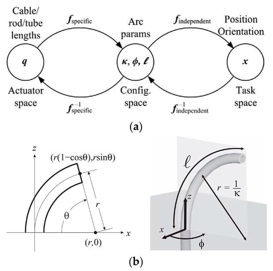
The advantage of the piecewise constant curvature assumption lies in the possibility of breaking down kinematics into two maps
[56], as exemplified in
Figure 7a
[54]. One map relates the joint or actuator space
𝑞 to the configuration space parameters describing CC arcs. The second map translates the configuration space into the task space, involving a spatial curve detailing position and orientation along the backbone. The actuator variable here primarily pertains to cable length. The configuration space comprises elements like curvature
𝜅(𝑞); the plane’s angle containing the arc
𝜙(𝑞); and the arc length (
𝓁(𝑞), at times denoted as
𝑠∈[0 𝓁]), as illustrated in
Figure 7b. Alternatively, the relation
𝜃=𝜅𝑠 permits parameterization based on the angle
𝜃
of the arc’s curvature
[57].
Figure 7. (
a) Illustration of the three spaces and the interrelated mappings that define the kinematics of constant-curvature robots, and (
b) the scenario when the angle
θ is zero, resulting in the arc lying in the x-z plane. An increase in the angle
θ rotates the arc out of the x-z plane. Notably, the figure highlights the “arc parameters” that describe a circular arc, specifically curvature (
κ), plane (
ϕ), and arc length (l). The coordinate axes shown in both sub-figures belong to the fixed spatial frame
[54].
3.2. Kinematics Modelling
3.2.1. Forward Kinematics
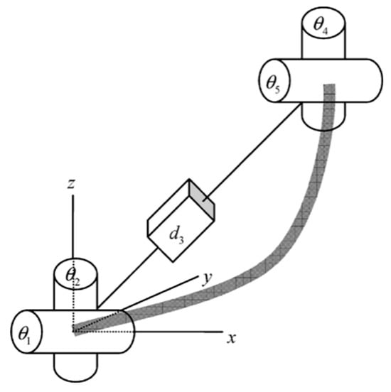
Contemporary methods for forward kinematics analysis encompass the widely used Denavit–Hartenberg (D-H) parameter method
[56]. This technique involves establishing a coordinate system for each connecting rod; describing the positional and orientational transformations within these coordinate systems; and subsequently constructing a comprehensive kinematic model, as shown in
Figure 8.
Figure 8. A section of a continuum robot modeled as a robust, semi-transparent line, which is achieved through a coupled link and joint arrangement
[56].
3.2.2. Inverse Kinematics
The process of solving inverse kinematics for continuum robots is inherently challenging. In the case of continuum robots with constant curvature (CC), the initial step typically involves establishing an inverse mapping, known as the robot-independent inverse mapping, between the task space and the configuration space. This mapping is aimed at determining the arc parameters that govern various segments of the robot, ultimately aligning them with the desired tip orientation
[54]. However, when dealing with continuum robots featuring numerous cross-sections, obtaining all conceivable solutions can be a complex task. To address this, three commonly used methods have emerged.
3.3. Dynamics Modelling
In general, the deformation of a continuum robot can be accurately described by kinematics under typical operating conditions. However, when external factors introduce interference, or when the robot operates at high speeds, the kinematic model may fall short of accurately representing the dynamic deformation process. In earlier studies dating back to 1994, dynamics models for continuum robots were approximated using principles from continuum mechanics
[58]. Despite this method’s approximation, it produced expressions that could be efficiently computed in a highly parallel manner, irrespective of the number of DOF. The accuracy of this approach was confirmed through comparisons with the Lagrange formula for the dynamics of lumped mass manipulators.
4. CDCR Motion Planning
Upon completing the kinematic and dynamic analysis of CDCRs, the next essential step is motion planning. This phase is critical for achieving safe, efficient, and reliable robot motion. Motion planning for continuum robots is built on the foundations of path planning and trajectory planning
[59]. Path planning focuses on defining a sequence of path points connecting two locations, A and B, based solely on geometric parameters and independent of time considerations. In contrast, trajectory planning enhances path planning by incorporating time-related information. It is particularly concerned with aspects such as displacement, velocity, and acceleration of robotic motion, with the objective of ensuring smooth motion profiles and controlled motion speeds
[60].
Motion planning encompasses the determination of suitable trajectories and action sequences through algorithmic and strategic approaches. This process is essential for guiding the robot in achieving specific goals or tasks. It encompasses considerations such as the initial state, target state, motion constraints, environmental information, and the selection of an appropriate path and action sequence to accomplish the desired motion. Notably, in the context of CDCRs, motion planning is not limited to planning for the end effector alone; it also encompasses planning for the entire backbone.
In cases where obstacles are present within a continuum robot’s workspace, motion planning is crucial for charting collision-free paths that allow the robot to reach predefined poses and complete its tasks. Avoiding collisions with obstacles is the foundational requirement of motion planning for continuum robots. Additionally, in the process of transitioning between different attitudes, optimal paths and action sequences are selected to minimize specific criteria, such as time, energy consumption, or distance. This optimization enhances motion efficiency and robot performance, constituting the second requirement of motion planning.
During the execution of operational tasks, CDCRs face varying obstacle distributions within their environments. These scenarios can generally be classified into three categories based on the obstacle density:
-
Tunnel type: In this scenario, obstacles are densely distributed, and the feasible workspace for the manipulator resembles a pipeline. This configuration is particularly suitable for applications in fields such as pipeline cleaning, endoscopic surgery in the human large intestine, and internal maintenance of aerospace engines, all of which require minimal invasion.
-
Scattered obstacle type: Obstacles are dispersed throughout the workspace in the form of objects or surfaces. This situation is found in tasks involving narrow openings (e.g., firefighting through narrow doors and windows), automatic object retrieval from supermarket shelves (unmanned supermarkets), and similar contexts.
-
Barrier-free: This scenario involves no obstacles in the workspace, allowing the manipulator to reach its target position freely. It is encountered in settings like underwater environments (cleaning underwater cages), routine tasks (object manipulation, desktop writing, posture teaching), and more.
The distribution of obstacles in the environment, in combination with the manipulator’s specific configuration (e.g., fixed base on a straight slide rail or a manipulator fixed on a 6-DOF platform), results in different motion planning approaches. Researchers typically develop distinct motion planning schemes tailored to each of these situations.
In summary, overcoming the most challenging scenarios paves the way for solving simpler problems. For instance, if a CDCR can navigate a tunnel-type obstacle, it becomes more straightforward to address scenarios with scattered obstacles, and even cases with no obstacles. Indeed, most researchers choose to develop motion planning algorithms starting from situations with the highest obstacle density. Traversing tunnel-type obstacles poses the primary challenge of maintaining the body’s shape along the path while moving the robot’s tip to a new position
[61].
5. CDCR Motion Control
Robot control involves the study of determining the precise actuation required to achieve the desired state for executing a given task. The state of a CDCR encompasses various aspects, including the position and orientation of the end effector, the robot’s configuration, its stiffness, and related motion performance
[62]. In contrast to rigid robots, the control of CDCRs presents additional challenges, such as dealing with redundant DOF, cable deformation due to tension, and S-shaped deformation of the robot’s backbone
[63][64]. The essence of motion control lies in efficiently attaining the desired robot state under these unique conditions. Existing control methods can be classified into three categories based on robot modeling techniques: model-based control
[65], model-free control, and hybrid control
[66].
5.1. Model-Based Control
Model-based control necessitates the consideration of the mapping between the actuation space, joint space, and task space. To achieve effective control, enhancing the accuracy of the robot model is often required (specifically, improving the robot’s configuration accuracy within the piecewise constant curvature model). Taking the VC model as an example, drive feedback and attitude feedback are employed to mitigate model errors and enhance real-time control accuracy, including encoders, torque sensors, electromagnetic sensors
[67][68], analytical calculation
[69], visual feedback
[70][71], flexible sensors, etc. Drive feedback assists in tracking and compensating for errors related to actuator joints (e.g., cable friction, coupling, hysteresis
[72]). Attitude feedback allows the task space controller to directly influence the robot’s moving target, providing robustness against model uncertainty. It is noteworthy that, compared to low-level control systems in the actuation space, control systems in the joint space tend to be more stable, facilitating higher frequencies and better dynamic performance
[73].
5.2. Model-Free Control
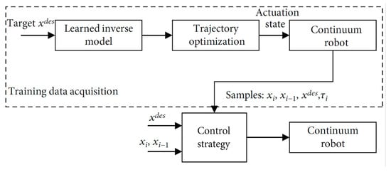
Model-free approaches (as depicted in
Figure 9) offer a solution to circumvent the complexities of using intricate kinematic and dynamic models of manipulators, along with the need for precise calibration. These approaches rely on data-driven techniques, such as machine learning and empirical methods, making them an effective alternative. They operate independently of joint space and can provide robust and stable performance, particularly when model-based methods face challenges like highly nonlinear systems or unstructured environments
[74].
Figure 9. Schematic diagram of learning-based control strategy
[62].
5.3. Hybrid Control
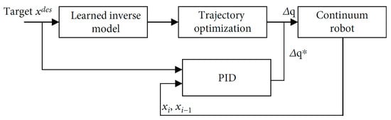
Given the uniqueness of each robotic structure and the discrepancies between drive and model descriptions, the adaptability of different continuum robot structures poses added challenges for learning methods. Hybrid model control, illustrated in
Figure 10, strikes a balance between the reliability of model-based control and the robustness of data-driven approaches
[62]. This approach integrates model-based and model-free methods at different kinematic layers
[73] or employs models to guide the learning process
[65].
Figure 10. Schematic diagram of the hybrid control strategy
[62]. (
∆q*is the calculated value and
∆q is the actual value.)
Reference control strategies include the hybrid adaptive control framework
[75] and control methods based on the Koopman operator theory
[76][77]. Experimental results indicate that the hybrid control method effectively compensates for uncertain factors, such as friction, driving tendon relaxation, and external loads during robot motion
[62]. It also addresses the ambiguity in selecting discrete state sets for structures with infinite DOF
[76].
The three aforementioned motion control methods underscore researchers’ commitment to enhancing the accuracy of continuum robot models and achieving precise target poses. However, they appear to overlook the potential limitations in realizing the desired high-precision model and full-arm attitude control from the base end. Contact constraints in the environment introduce uncertainty into the robot model, even with feedback control, leading to the likelihood that the robot’s configuration may not reach the expected shape. Hence, the primary challenge at present lies in the conflict between increasingly accurate models and severely limited driving DOF.
For CDCRs, two potential paths emerge. The first involves sacrificing some flexibility to address the S-shaped deformation issue, improving the accuracy of the backbone model based on the piecewise constant curvature assumption, and focusing on enhancing control accuracy. The second path involves maximizing the flexibility of CDCRs based on the VC model. In this approach, the robot’s arrival pose is sensed through a robust feedback system, and potential motion poses under various loads are predicted using a powerful learning system. However, this approach may sacrifice control precision and limit the robot’s ability to perform common tasks in human society. Achieving a balance between these two paths is essential, with variable stiffness control playing a pivotal role.
 +1 credit