Your browser does not fully support modern features. Please upgrade for a smoother experience.
Submitted Successfully!
 +1 credit
Thank you for your contribution! You can also upload a video entry or images related to this topic.
For video creation, please contact our Academic Video Service.
| Version | Summary | Created by | Modification | Content Size | Created at | Operation |
|---|---|---|---|---|---|---|
| 1 | Yeqing Wang | -- | 4445 | 2024-02-05 15:51:37 | | | |
| 2 | Lindsay Dong | Meta information modification | 4445 | 2024-02-07 02:05:48 | | |
Video Upload Options
We provide professional Academic Video Service to translate complex research into visually appealing presentations. Would you like to try it?
Cite
If you have any further questions, please contact Encyclopedia Editorial Office.
Wang, Y.; Fan, Y.; Zhupanska, O.I. Lightning Strike Damage Assessments of Composites. Encyclopedia. Available online: https://encyclopedia.pub/entry/54772 (accessed on 08 June 2026).
Wang Y, Fan Y, Zhupanska OI. Lightning Strike Damage Assessments of Composites. Encyclopedia. Available at: https://encyclopedia.pub/entry/54772. Accessed June 08, 2026.
Wang, Yeqing, Yin Fan, Olesya I. Zhupanska. "Lightning Strike Damage Assessments of Composites" Encyclopedia, https://encyclopedia.pub/entry/54772 (accessed June 08, 2026).
Wang, Y., Fan, Y., & Zhupanska, O.I. (2024, February 05). Lightning Strike Damage Assessments of Composites. In Encyclopedia. https://encyclopedia.pub/entry/54772
Wang, Yeqing, et al. "Lightning Strike Damage Assessments of Composites." Encyclopedia. Web. 05 February, 2024.
Copy Citation
Lightning strike events pose significant challenges to the structural integrity and performance of composite materials, particularly in aerospace, wind turbine blade, and infrastructure applications.
composite materials
lightning strike
laboratory testing
predictive modeling
material degradation
1. Introduction
Composite materials play a prominent role in the design of high-performance structures capable of withstanding extreme structural loads [1]. Polymer matrix composites revolutionized the structural design of aerospace structures due to their light weight, high stiffness, and high strength. At the same time, the survivability of polymer matrix composites subjected to harsh environmental conditions is still of concern. Lightning strikes [2] are high-risk and low-probability (e.g., one and a half strikes per year per airplane) events that present significant threats to polymer matrix composite structures. Carbon fiber–polymer matrix composites (CFRP) are particularly vulnerable to high-energy lightning strike events due to their relatively low electrical and thermal conductivities as well as limited service temperature and significant degradation in properties above the decomposition temperature. The combined effect of these factors is manifested in the lightning-induced heat damage zone. The damage induced by a lightning strike is difficult to prevent [3], though protections, such as copper foils, have been applied [1]. By accurately predicting the behavior of composite materials under lightning strikes, it is possible to enhance the design and safety of various structures and components.
Accurate models for simulating lightning strike on composites require a comprehensive approach that considers various factors that reflect the damage nature of a lightning strike on composite materials. This includes, first of all, electro–thermal–mechanical coupling, which involves accounting for the intricate interactions between electrical, thermal, and mechanical phenomena within the composite material during a lightning strike, requiring sophisticated multi-physics simulations. Detailed information on the material’s electrical, thermal, and mechanical properties, particularly with consideration for temperature-dependent behavior is another critical aspect that high-fidelity models need to address. Establishing models that predict temperature-dependent properties can significantly enhance the accuracy of simulations and better capture the dynamic response of composites during lightning strike events. In addition to thermal damage, mechanical damage caused by thermal stress and shockwave pressure [4][5][6] deserves attention. Effective damage prediction methods are essential for assessing the potential effects of lightning strikes on composite materials. These methods need to consider the damage characteristics of composite materials, including thermal decomposition of the matrix, delamination, matrix cracking, and fiber breakage, under the high-energy conditions of a lightning strike [7].
Laboratory lightning strike tests are crucial for providing empirical data to validate and improve predictive models. These tests aid in understanding the behavior of composites under lightning conditions, enabling the development of accurate material models and simulation parameters. The validation of predictive models is a key step toward ensuring their reliability. The integration of experimental data from laboratory tests, as well as in-service monitoring and inspection data, is crucial to validating the accuracy of the models and build confidence in their predictive capabilities. The extent of the damage obtained via optical analyses, C-scans and X-rays, is frequently used for the verification and validation of numerical simulation models for describing the damage induced in composite materials by an artificial lightning strike [3].
2. Laboratory Lightning Strike Tests
Actual lightning strike discharges in nature are highly uncertain and extremely difficult to control for experimental implementation and instrumentation. Thus, simulated lightning strike tests are normally conducted in the laboratory condition for the following three purposes: (i) the observation and identification of the physics and failure mechanisms involved in the lightning strike interaction with materials and structures, (ii) the assessment of the damage tolerance of composite materials against a lightning strike, and (iii) the evaluation of the effectiveness and performance of conventional and innovative lightning strike protection solutions. Depending on whether the testing material or structure is electrically conductive or non-conductive, laboratory lightning strike tests are often classified into two categories: (i) high-current tests and (ii) high-voltage tests. If the material is electrically conductive, such as CFRP composites (e.g., for aircraft fuselage), high-current (up to 200 kA) lightning strike tests should be performed since the thermal damage caused by the conduction of the lightning strike current represents the primary damage. Whereas if it is electrically non-conductive, such as glass fiber-reinforced polymer (GFRP) composites (e.g., for wind turbine blades), high-voltage (1000 kV/µs) lightning strike tests should be performed as the puncture damage due to the dielectric breakdown is the primary damage [8].
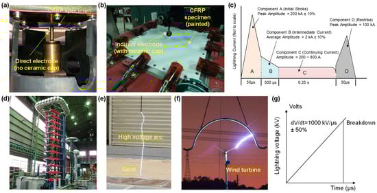
High-current lightning strike tests for CFRP composites typically use a cathode–anode configuration to produce a high-intensity electric arc in the air. Figure 1 shows examples of the testing setups [9]. In the U.S., such a testing capability is available at the National Institute of Aviation Research at Wichita State University [10], High Voltage Lab at Mississippi State University (MSU-HVL) [11] (Figure 1a), and the National Technical Systems in Pittsfield, MA, USA [12] (Figure 1b), etc. Depending on the polarity of the electrode used in the test, the CFRP composite specimen can either serve as a cathode or an anode. The produced electric arc attaches to the surface of the CFRP composite specimen, thereby simulating the lightning strike interaction with the CFRP composites. The actual lightning strike discharge contains multiple strokes with different durations and magnitudes of the electric current. This is simulated by a standard four-component current waveform (see Figure 1c). High-voltage lightning strike tests are typically for electrically non-conductive materials, such as glass fiber-reinforced–polymer matrix composites, which are commonly used for radome for aircraft and wind turbine blades. Figure 1d shows a Marx high-voltage generator produced by Haefely test AG in Japan [13], and Figure 1e shows a high-voltage lightning test conducted on sand at MSU-HVL [14]. Figure 1f shows a high-voltage lightning impulse test on a wind turbine conducted by a research group of Wuhan University in China [15]. The lightning voltage waveform used in the tests is suggested also by the SAE ARP-5412 [16] and is shown in Figure 1g.
Figure 1. Simulated lightning strike tests: (a) high-current test setup with a direct electrode at the High Voltage Lab at Mississippi State University (MSU-HVL) [9], (b) high-current test setup with an indirect electrode at the National Technical Systems in Pittsfield, Massachusetts [12], (c) standard lightning high-current test waveform [16], (d) Marx high-voltage generator produced by Haefely test AG in Japan [13], (e) high-voltage lightning test on sand at MSU-HVL [14] (f) high-voltage lightning test on a wind turbine in China [15], (g) standard lightning high-voltage test waveform A suggested by the SAE 5412 standard [16].
Generating the four current waveforms (see Figure 1c) sequentially in the laboratory condition is still challenging due to the limitations of experimental capabilities. Most research papers [17][18][19][20][21][22][23][24][25] related to the lightning strike testing of CFRP composites recognized that the electric currents of waveforms B, C, and D are much lower than that of waveform A and assumed that the waveform A current contributes to the majority of the damage in the CFRP composites. Thus, these studies conducted only simulated lightning strike tests (and simulations) with a waveform A current. With the recent development of testing capabilities, a limited number of recent experimental studies have produced multiple and sequential waveforms (e.g., waveforms C and D, waveforms A, B, and C) [26][27][28]. More recently, one notable study successfully produced electric arcs with a complete sequence of all four waveforms [29]. These studies with combined waveforms demonstrated that considering only the waveform A significantly underestimates the lightning strike damage in the composites. For instance, a single waveform A current can cause a damage depth of 0.513 mm and a damage area of 1104 mm2 in a CFRP composite specimen, whereas combined waveforms A, B, C, and D result in a damage depth of 1.280 mm and a damage area of 2790 mm2 [29]. Conducting only waveform A tests could be sufficient for some comparison studies (e.g., comparing the lightning strike damage in CFRP composites with and without lightning strike protections). However, it is clearly insufficient if the purpose of the experimental study is to understand the damage mechanisms or assess the damage tolerance of the CFRP composites (especially for unprotected CFRP composites) in actual lightning strike conditions. The underestimated damage results from waveform A tests will lead to a less conservative design of CFRP composite structures and hence may lead to risks of structural failure during operation and a reduced structural lifetime.
To answer the first question, the characteristics of laboratory electric arcs and actual lightning strikes are summized and compared in Table 1. It can be seen that the laboratory electric arc and the actual lightning strike share similarities in the context of peak current, peak power, action integral, and discharge mechanisms. However, differences still exist in the levels of electric voltage and acoustic shock wave and the environments between the laboratory condition and the actual flight/operation conditions (e.g., altitude, aircraft movement, and temperature and humidity). These differences may lead to the underestimation of the lightning strike damage in the CFRP composites. For example, the voltage of the laboratory lightning strike test is at least 1000 times lower than the actual lightning strike voltage. Such a reduction in the voltage will potentially lead to the underestimation of the dielectric breakdown damage. The moisture will lead to reductions in dielectric breakdown strength and hence make the composites more prone to dielectric breakdown damage [30][31].
Table 1. Comparison of laboratory lightning strike characteristics with actual lightning strikes.
| Actual Lightning Strike | Laboratory Electric Arc | |
|---|---|---|
| Peak current | 200 kA (±10%) | 200 kA (±10%) |
| Peak power | ~1011 W/m | ~1011 W/m |
| Action integral | 2 × 10⁶ A2·s (±20%) | 2 × 10⁶ A2·s (±20%) |
| Discharge mechanism | Breakdown of the air | Breakdown of the air |
| Arc length | 4000 m | 3~10 mm |
| Arc radius | 1 m | A few centimeters |
| Peak voltage | In the order of tens of kilovolts | 10~120 million volts |
| Acoustic shock wave | ~400 Pa | 2 Pa (recorded with microphones at 1.8 m in a 5 kA experiment) [32] |
3. In Situ and Post-Strike Characterization and Imaging
To understand the material behavior and damage mechanisms of the CFRP composites subjected to lightning strikes, in situ and post-strike characterization and imaging are effective tools. The in situ method is challenging due to the extremely short duration of the lightning strike, whereas the post-strike method is relatively more achievable and most widely used in the current lightning strike experimental studies.
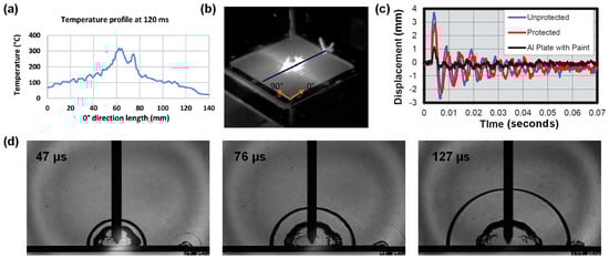
In situ characterization and imaging are crucial for understanding the time-varying responses of the CFRP composites during a lightning strike. For example, HD thermal cameras have been used to visualize the flow of the lightning electric current on the surface of a CFRP composite [6][12][33] and record the surface temperature history (see Figure 2a,b). Kumar et al. [33] used a thermal camera and captured the directional preference, which shows that the electric current flows mostly along the fiber direction (see Figure 2b). Moreover, high-speed digital image correlation systems and optical laser measurement sensors have been used to record the displacement history of the CFRP composite panels during lightning strike tests [12], which discovered the strong oscillations of displacement during lightning strike impact (see Figure 2c) and that the amplitude of the oscillation changes with different surface conditions (i.e., protected, unprotected, and with aluminum paint) (see Figure 2c). Furthermore, researchers have used the shadowgraph technique in lightning strike tests, which enabled them to visualize the shockwave propagation and the high-temperature gas generation due to the vaporization of resin and sublimation of carbon fiber [34], as shown in Figure 2d. The technique allowed them to study the effects of indirect vs. direct electrodes on the shockwave characteristics and resulting damage in CFRP composites. They found that shock waves generated by the electric discharge played a relatively insignificant role in damaging the CFRP composite.
Figure 2. In situ characterization and imaging in simulated lightning strike tests: (a) temperature profile on the surface of a composite specimen measured using a thermal imager [33], (b) thermography image showing the electric current conduction path on the composite surface [33], (c) displacement of the composite specimen during simulated lightning strike [12], and (d) evolution of the arc and the shock wave generated during the lightning strike test using the shadowgraph imaging technique [34].
The post-strike characterization and imaging can be classified into two categories: non-destructive and destructive methods. The non-destructive method includes taking HD camera photos and using ultrasonic inspections and X-ray tomography. On the other hand, the destructive method includes fractography using scanning electron microscopy (SEM), optical microscopy, destructive sectioning, and residual strength tests using three-point or four-point flexural tests or compression-after-impact (CAI) tests. One recent study systematically pointed out the modifications necessary to standard CAI specimen geometry and test setup design to inflict specimen failure at the lightning damage site [35]. The ultrasonic inspection technique provides a projected area and position of the delamination in the CFRP composites. Specifically, a C-scan can be used to identify the extent of the delamination in the in-plane direction, while a B-scan provides the information of the depth of the delamination across the thickness of the composite. ImageJ software can be used to process the images obtained from the ultrasonic inspection and estimate the delamination area and depth. The fractography using microscopic imaging and destructive sectioning allows us to see the detailed microstructure at the lightning damage site and identify the different failure modes (i.e., fiber breakage and pullout, charring, matrix cracking, fiber–matrix debonding, delamination) and quantify the extent or number density of each failure mode.
4. Material Characterization and Modeling
The behavior of composite materials under lightning strike conditions is intricately influenced by temperature-dependent properties. Temperature-dependent properties play a pivotal role in capturing the dynamic response of composites subjected to lightning strike events. The relevant material properties include electrical, thermal, mechanical, and viscoelastic characteristics, which undergo significant variations as the temperature changes during a lightning strike. Electrical properties, such as conductivity and permittivity, are inherently temperature-dependent and can markedly influence the flow of current within the composite material during a lightning strike. Accurately modeling these properties at different temperatures is essential for predicting the electrical behavior of composites under varying environmental conditions.
Note that electrical conductivities reported in [17][20][36] were obtained experimentally. Studies [19][21] did not report how the electrical conductivities were determined. As for the temperature-dependent electrical properties, various assumptions were made. In [17], the electrical conductivity in the through-the-thickness direction of the CFRP is assumed to increase linearly from 7.94 × 10⁻⁷ S/m to 0.1 S/m (1.3 × 10⁵ times) when lightning-induced surface recession starts to occur at a temperature above 600 °C until the carbon fiber sublimation temperature at around 3000 °C.
As for carbon fibers, their temperature dependence was found to be similar to that of semiconductors [37]. Typically, the electric conduction of a semiconductor is governed by lattice scattering when carrier concentration is intrinsic, particularly at high temperatures (>100 °C). The temperature-dependency when T > 100 °C can be characterized using the Arrhenius law.
Thermal properties, including thermal conductivity and heat capacity, influence the dissipation and propagation of heat generated during a lightning strike. Modeling the temperature-dependent thermal properties of composites is crucial for simulating the thermal response and potential damage mechanisms, aiding in the evaluation of the material’s thermal performance under extreme conditions. It is well known that properties of polymers start to deteriorate at temperatures above that of glass transition. As for temperature-dependent thermal conductivity, experimental studies conducted on epoxy resin above the glass transition temperature but below the thermal decomposition temperature [38][39] showed a linear increase in the thermal conductivity with temperature until 177 °C. No reported experimental measurements for thermal conductivity have been found at temperatures above 177 °C. As for the specific heat, polymers do exhibit a nonlinear increase in specific heat prior to the start of thermal decomposition (i.e., ~300 °C for epoxy resins) [40].
The thermal decomposition (pyrolysis) of polymers consists of complex chemical reactions and the formation of new material phases, a solid pyrolytic phase, and pores filled with pyrolysis gases. These processes lead to drastic reductions in the polymer’s thermal conductivity and specific heat with temperature. As a result, significant reductions in the transverse thermal conductivity and specific heat of the polymer matrix composites are predicted [41].
Moreover, the mass loss of a polymer is strongly dependent on the heating rate. As the heating rate increases, the mass loss decreases and the temperature, at which the polymer is fully decomposed, increases. Thermal gravimetric analysis (TGA) experimental data show that the mass loss of carbon fiber-reinforced polymer (CFRP) composites under a heating rate of 50 °C/min is about 17% lower than that under a heating rate of 10 °C/min in nitrogen at 400 °C, and the difference continues to increase as the temperature increases [42].
As for the char, it is a highly porous solid carbonaceous residue and is a byproduct of the pyrolytic thermal decomposition. Polymers, when exposed to high temperatures, are decomposed by three major mechanisms; these are random chain scission, chain-end scission, and chain stripping [43][44]. Different classes of polymers exhibit different reaction mechanisms, and the overall char content that is produced differs.
Mechanical properties, such as stiffness, strength, and viscoelasticity, also exhibit temperature sensitivity, affecting the material’s response to mechanical loads induced by the thermal and electromagnetic effects of a lightning strike. Experimental data show that the elastic modulus of epoxy exhibits a steep decrease as the temperature approaches its glass transition temperature [45]. Poisson’s ratio of epoxy also exhibits a strong dependence on the temperature. Previous experimental studies reported an increase in Poisson’s ratio up to a value of 0.5 at the glass transition temperature [46][47][48]. A detailed micromechanics-based study on the temperature-dependent elastic properties of CFRP composites at high temperatures was reported in [49].
5. Lighting Electric Arc Plasma Modeling
There are two main purposes of modeling the lightning electric arc. The first purpose is to acquire the accurate loading condition, including the heat flux, current density, plasma pressure, and electromagnetic force impinging on the surface of the CFRP composite material as well as the arc radius expansion. Note that in many existing lightning strike modeling studies, the applied heat flux and current density are based on assumed profiles and assumed arc radii [19][20][50][51][52][53][54]. The second purpose is to understand the interaction between the electric arc and the material behavior of the composite specimen, for example, how do the particles vaporized from the composite material during the lightning strike affect the electric arc characteristics [55]. Overall, studies on the modeling of lightning electric arc plasma are still scarce to date, primarily due to the challenges in the numerical implementation and the associated expensive computational run time (some can take 50 days [56]). Therefore, although modeling the lightning electric arc plasma is critical for determining the accurate loading conditions and studying the complex interaction between the composite and the electric arc, the trade-off between the computational cost and the improvement in the accuracy of the prediction remains a significant issue. For example, studies have shown that when using traditionally assumed arc radius loading, the moderate and severe lightning damages were underpredicted by 61% and 2.75%, respectively, while using the arc radius loading predicted from a plasma model, the moderate lightning damage was underpredicted by 50% and the severe lightning damage was overpredicted by 129.5% [57][58].
5.1. Lightning Electric Arc Plasma–Magnetohydrodynamic Model
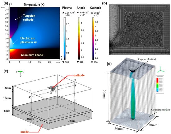
This approach currently used to model the lightning strike electric arc plasma follows the same magnetohydrodynamic (MHD) method used to model the electric arc for welding applications. The differences between the lightning strike electric arc and the welding electric arc are as follows: (1) the lightning strike electric arc is produced in the air, whereas the welding arc is produced mostly in the inert gas environment (e.g., argon); and (2) the electric current for lightning strike electric arc consists of four waveforms, and the peak current can reach 200 kA, whereas the electric current for the welding arc is normally a constant current ranging from 100 A to 800 A. The MHD-governing equations include Maxwell’s equations, the Navier–Stokes equation, the heat transfer energy balance equation, and the conservation equation of electric charge. These equations are classical and widely known to the research community. The typical computational domain consists of a cathode, anode, and the air (or inert gas for a welding arc). Figure 3 shows a few examples of the computational problem setup for the MHD model. The model is often simplified in an axis-symmetric configuration to reduce the computational cost (see Figure 3a,b). Here, one needs to be careful with using the axis-symmetric configuration. Such a configuration is valid only for isotropic materials (e.g., copper, aluminum, steel). When it comes to laminated composite materials, since they are anisotropic, the axis-symmetric configuration is invalid regardless of modeling a unidirectional or multidirectional laminate. Thus, a three-dimensional (3D) model needs to be created (see Figure 3c,d).
Figure 3. Examples of computational setups for modeling the lightning strike electric arc plasma using the MHD method for predicting the plasma temperature, heat flux, current density, arc pressure, etc.: (a) 2D axis-symmetric model [55], (b) example of the mesh used for the 2D axis-symmetric plasma model [57], (c) 3D lightning strike electric arc plasma model [59], and (d) 3D predictions of the plasma temperature [60].
Researchers have used the MHD lightning strike electric arc plasma model not only to determine the loading conditions from the electric arc to the surface of the CFRP composites [56][57][59][61], but also to study the effect of testing configurations on the characteristics of the electric arc and the resulting damage in the anode material (e.g., metallic materials, CFRP composites) [57][62][63][64]. The latter studies have demonstrated that the arc gap (i.e., the distance between the cathode and anode) plays a significant role in determining the loading condition in the electric arc. For example, it was shown that the heat flux decreased by 80% when the arc gap was increased from 1 mm to 10 mm [63]. Some other studies have also investigated the effect of the size of the electrode. Moreover, the choice of using an indirect electrode or direct electrode for the simulated lightning strike test is still in debate. Studies have used the MHD model and investigated the effect of the metal vapor produced during the vaporization of the initiation wire used in the indirect electrode setup. It was found that the metal vapor significantly changes the net emission coefficient and the electrical and thermal conductivities of the electric arc, which results in significant changes in the damage of the tested material [64][65][66].
5.2. Lightning Plasma–Composite Damage Coupled Model
Recall that the purpose of modeling the lightning strike electric arc plasma is to determine the loading conditions on the lightning-attached surface of the CFRP composites. After that, the determined loading conditions are used in the lightning strike composite damage model for the damage prediction. There are typically two approaches for achieving this: one is to sequentially couple the lightning composite damage model from the lightning electric arc plasma model. For example, Millen et al., [57][67] predicted the lightning loading conditions using a COMSOL MHD lightning strike model for a Waveform B current first. Then, the output of the plasma model, i.e., the predicted loading conditions were transferred to a separate material damage simulation as model input to predict the material damage under lightning strike loading. The mesh and loading boundary conditions of the composite material were automatically generated based on the predicted output of the plasma model. The other approach is to synchronously couple the lightning plasma model with a lightning thermal damage model. This approach improves the fidelity of the model as it captures the in situ interaction between the plasma and the composite material, which is more computationally challenging. Studies using this approach are limited.
In addition to the challenges discussed in the previous section related to the lightning strike electric arc plasma model itself, there are other challenges that researchers are facing in coupling the plasma model with the thermal damage model. A few important challenges that future work is recommended to address include (1) developing strategies to effectively exchange information between the plasma model and the thermal damage model while maintaining the numerical accuracy and numerical convergence of both models, (2) developing strategies to handle the moving boundary conditions in both the plasma model and the thermal damage model caused by the progressive material removal (i.e., surface resin vaporization and fiber sublimation), and (3) develop methods to account for the effect of particles vaporized from the material during lightning strike on the plasma characteristics.
Significant research progress has been made on the modeling of the lightning strike material and damage responses of CFRP composites since Ogasawara et al. [17] first presented an electric–thermal coupled model for simulating the lightning strike response of CFRP composites in the year of 2010. Progress has been mainly achieved in the following aspects. (i) More physically representative lightning strike loading conditions have been used in the model to account for the electric arc radius and the arc expansion, as well as the spatial variation in the heat flux and current density within the electric arc. These loading conditions are either assumed or determined based on experimental data from welding arcs or using a separate/coupled MHD model, which have significantly improved the fidelity of the lightning strike damage model and the accuracy of the prediction [58]. (ii) Temperature-dependent material properties, including density, electrical conductivity, thermal conductivity, and specific heat have been used in the electric–thermal coupled model to understand the effect of material degradation on the thermal damage [68][69]. (iii) The pyrolytic behavior of the polymer matrix at elevated temperatures has been incorporated into the electric–thermal coupled model to account for the resin decomposition caused by Joule heating [51][70][71]. (iv) The mechanical forces caused by the lightning strike, such as the acoustic shock wave and the arc pressure, have been either separately modeled or coupled to the electric–thermal model [20][50][72]. (v) The effect of the protection layer, such as the expanded copper mesh on the lightning strike damage response of the CFRP composite substrate has been modeled. (vi) Delamination caused during the lightning strike impact has been modeled using a cohesive zone method with mechanical interfacial properties (e.g., interface stiffness, strength, and fracture energy) [73][74]. (vii) Ablation caused due to the resin vaporization and carbon fiber sublimation has been modeled using element deletion methods [52][53][54]. (viii) Thermal expansion has been considered with the heating rate- and strain rate-dependent material properties to understand the thermal strains caused due to the rapid heating and its constraints relative to the experimental boundary conditions [75][76].
Overall, despite significant progress having been made on the modeling of lightning strike damage response of CFRP composites, improving the model fidelity is still challenging as described above. In parallel with the development of more advanced models, model validation also needs to be improved to provide more confidence on the validity and effectiveness of models. Currently, validations of the lightning strike models have been mostly achieved by comparing the predictions of the extent of delamination (depth and area) and surface vaporization. Future research is recommended to further validate models by also comparing against the extent of the charred region, the temperature history on the back side of the CFRP composite, the displacement history of the CFRP composite, the exact mass loss of the composite, and the extents of the fiber breakage and matrix cracking.
References
- Kamiyama, S.; Hirano, Y.; Okada, T.; Sonehara, T.; Ogasawara, T. I–V characteristics and temperature response of unidirectional CFRP exposed to simulated lightning current in the fiber direction. Compos. Part A Appl. Sci. Manuf. 2022, 162, 107111.
- Kawakami, H.; Feraboli, P. Lightning strike damage resistance and tolerance of scarfrepaired mesh-protected carbon fiber composites. Compos. Part A Appl. Sci. Manuf. 2011, 42, 1247–1262.
- May, M.; Schopferer, S. On the Relationship between Lightning Strike Parameters and Measured Free Surface Velocities in Artificial Lightning Strike Tests on Composite Panels. J. Compos. Sci. 2023, 7, 268.
- Sasikumar, A.; Costa, J.; Trias, D.; Gonzalez, E.V.; Garica-Rodriguez, S.M.; Maimi, P. Unsymmetrical stacking sequences as a novel approach to tailor damage resistance under out-of-plane impact loading. Compos. Sci. Technol. 2019, 173, 125–135.
- Wan, G.; Dong, Q.; Li, T.; Sun, X.; Jia, Y. Simulated Analysis of Lightning-induced Mechanical Damages in Fiber Reinforced Composites Based on a Pyrolysis-affected Damage Constitutive Model. Appl. Compos. Mater. 2022, 29, 2165–2184.
- Li, Y.; Sun, J.; Li, S.; Tian, X.; Yao, X.; Wang, B.; Zhu, Y.; Chen, J. Experimental study of the damage behaviour of laminated CFRP composites subjected to impulse lightning current. Compos. Part B 2022, 239, 109949.
- Wang, F.; Ma, X.; Wei, Z.; Wu, Y.; Huang, C. Lightning damage of composite material driven by multi-physics coupling. Compos. Sci. Tech. 2023, 233, 109886.
- Lin, W.; Wang, Y.; Aider, Y.; Rostaghi-Chalaki, M.; Yousefpour, K.; Kluss, J.; Wallace, D.; Liu, Y.; Hu, W. Analysis of damage modes of glass fiber composites subjected to simulated lightning strike impulse voltage puncture and direct high voltage AC puncture. J. Compos. Mater. 2020, 54, 4067–4080.
- Yousefpour, K.; Lin, W.; Wang, Y.; Park, C. Discharge and ground electrode design considerations for the lightning strike damage tolerance assessment of CFRP matrix composite laminates. Compos. Part B Eng. 2020, 198, 108226.
- Environmental Tests, National Institute of Aviation Research, Wichita State University. Available online: https://www.wichita.edu/industry_and_defense/NIAR/Laboratories/environmental.php (accessed on 19 December 2023).
- High Voltage Laboratory, Mississippi State University. Available online: https://www.ece.msstate.edu/high-voltage-lab/ (accessed on 19 December 2023).
- Szatkowski, G.N.; Dudley, K.L.; Koppen, S.V.; Ely, J.J.; Nguyen, T.X.; Ticatch, L.A.; Mielnik, J.J.; Mcneill, P.A. Common practice lightning strike portection characterization technique to quantify damage mechanisms on composite substrates. In Proceedings of the International Conference on Lightning and Static Electricity (ICOLSE), Seattle, WA, USA, 18–20 September 2013; NF1676L-15995. pp. 13–51.
- Hirano, Y.; Katsumata, S.; Iwahori, Y.; Todoroki, A. Artificial lightning testing on graphite/epoxy composite laminate. Compos. Part A Appl. Sci. Manuf. 2010, 41, 1461–1470.
- Hu, W.; Zhao, W.; Wang, Y.; Liu, Z.; Cheng, J.; Tan, J. Design optimization of composite wind turbine blades considering tortuous lightning strike and non-proportional multi-axial fatigue damage. Eng. Optimiz. 2020, 52, 1868–1886.
- Wen, X.; Qu, L.; Wang, Y.; Chen, X.; Lan, L.; Si, T.; Xu, J. Effect of wind turbine blade rotation on triggering lightning: An experimental study. Energies 2016, 9, 1029.
- ARP5412B; Aerospace Recommended Practice. SAE Aerospace: Warrendale, PA, USA, 1999.
- Ogasawara, T.; Hirano, Y.; Yoshimura, A. Coupled thermal–electrical analysis for carbon fiber/epoxy composites exposed to simulated lightning current. Compos. Part A Appl. Sci. Manuf. 2010, 41, 973–981.
- Wang, F.S.; Ding, N.; Liu, Z.Q.; Ji, Y.Y.; Yue, Z.F. Ablation damage characteristic and residual strength prediction of carbon fiber/epoxy composite suffered from lightning strike. Compos. Struct. 2014, 117, 222–233.
- Abdelal, G.; Murphy, A. Nonlinear numerical modelling of lightning strike effect on composite panels with temperature dependent material properties. Compos. Struct. 2014, 109, 268–278.
- Muñoz, R.; Delgado, S.; González, C.; López-Romano, B.; Wang, D.-Y.; Llorca, J. Modeling Lightning Impact Thermo-Mechanical Damage on Composite Materials. Appl. Compos. Mater. 2014, 21, 149–164.
- Liu, Z.Q.; Yue, Z.F.; Wang, F.S.; Ji, Y.Y. Combining Analysis of Coupled Electrical-Thermal and BLOW-OFF Impulse Effects on Composite laminate Induced by Lightning Strike. Appl. Compos. Mater. 2015, 22, 189–207.
- Kumar, V.; Yokozeki, T.; Karch, C.; Hassen, A.A.; Hershey, C.J.; Kim, S.; Lindahl, J.M.; Barnes, A.; Bandari, Y.K.; Kunc, V. Factors affecting direct lightning strike damage to fiber reinforced composites: A review. Compos. Part B Eng. 2020, 183, 107688.
- Li, Y.; Li, R.; Lu, L.; Huang, X. Experimental study of damage characteristics of carbon woven fabric/epoxy laminates subjected to lightning strike. Compos. Part A Appl. Sci. Manuf. 2015, 79, 164–175.
- Li, Y.; Li, R.; Huang, L.; Wang, K.; Huang, X. Effect of hygrothermal aging on the damage characteristics of carbon woven fabric/epoxy laminates subjected to simulated lightning strike. Mater. Des. 2016, 99, 477–489.
- Feraboli, P.; Miller, M. Damage resistance and tolerance of carbon/epoxy composite coupons subjected to simulated lightning strike. Compos. Part A Appl. Sci. Manuf. 2009, 40, 954–967.
- Chen, J.; Bi, X.; Liu, J.; Fu, Z. Damage investigation of carbon-fiber-reinforced plastic laminates with fasteners subjected to lightning current components C and D. Appl. Sci. 2020, 10, 2147.
- Guo, Y.; Xu, Y.; Wang, Q.; Dong, Q.; Yi, X.; Jia, Y. Eliminating lightning strike damage to carbon fiber composite structures in Zone 2 of aircraft by Ni-coated carbon fiber nonwoven veils. Compos. Sci. Technol. 2019, 169, 95–102.
- Guo, Y.; Xu, Y.; Zhang, L.; Wei, X.; Dong, Q.; Yi, X.; Jia, Y. Implementation of fiberglass in carbon fiber composites as an isolation layer that enhances lightning strike protection. Compos. Sci. Technol. 2019, 174, 117–124.
- Sun, J.; Yao, X.; Xu, W.; Chen, J.; Wu, Y. Evaluation method for lightning damage of carbon fiber reinforced polymers subjected to multiple lightning strikes with different combinations of current components. J. Compos. Mater. 2020, 54, 111–125.
- Hong, T.P.; Lesaint, O.; Gonon, P. Water absorption in a glass-mica-epoxy composite—. IEEE Trans. Dielectr. Electr. Insul. 2009, 16, 1–10.
- Morgan, B.; Madhukar, M.; Walsh, J.; Hooker, B.; Grandlienard, S. Moisture degradation of cyanate ester/S2 glass composite insulation systems. J. Compos. Mater. 2010, 44, 821–837.
- Wang, J.; Cao, J.; Cai, L.; Fan, Y.; Zhou, M.; Li, Q. Characteristics of Acoustic Response from Simulated Impulsive Lightning Current Discharge. High Volt. 2019, 4, 221–227.
- Kumar, V.; Yokozeki, T.; Okada, T.; Hirano, Y.; Goto, T.; Takahashi, T.; Hassen, A.A.; Ogasawara, T. Polyaniline-based all-polymeric adhesive layer: An effective lightning strike protection technology for high residual mechanical strength of CFRPs. Compos. Sci. Technol. 2019, 172, 49–57.
- Hirano, Y.; Sonehara, T.N.T.; Tokuoka, N. An experimental study on influence of shock-wave on composite lightning damage. In Proceedings of the 2019 International Conference on Lightning an d Static Electricity (ICOLSE), Wichita, KA, USA, 10–13 September 2019.
- Xu, X.; Millen, S.L.; Lee, J.; Abdelal, G.; Mitchard, D.; Wisnom, M.R.; Murphy, A. Developing Test Methods for Compression after Lightning Strikes. Appl. Compos. Mater. 2023, 30, 539–556.
- Kawakami, H. Lightning Strike Induced Damage Mechanisms of Carbon Fiber Composites. Ph.D. Thesis, University of Washington, Seattle, WA, USA, 2011.
- Sauder, C.; Lamon, J.; Pailler, R. Thermomechanical Properties of Carbon Fibres at High Temperatures (Up to 2000 °C). Compos. Sci. Technol. 2002, 62, 499–504.
- Chern, B.-C.; Moon, T.J.; Howell, J.R. Measurement of the temperature and cure dependence of the thermal conductivity of epoxy resin. Exp. Heat Transf. 1993, 6, 157–174.
- Farmer, J.D.; Covert, E.E. Thermal Conductivity of a Thermosetting Advanced Composite during Its Cure. J. Thermophys. Heat Tr. 1996, 10, 467–475.
- Chern, B.C.; Moon, T.J.; Howell, J.R.; Tan, W. New experimental data for enthalpy of reaction and temperature-and degree-of-cure-dependent specific heat and thermal conductivity of the Hercules 3501-6 epoxy system. J. Compos. Mater. 2002, 36, 2061–2072.
- Konduri, T.G.; Zhupanska, O.I. Micromechanics modeling of polymer matrix composites undergoing pyrolysis. In Proceedings of the American Society for Composites Thirty-Fifth Technical Conference, Virtual, 14–17 September 2020.
- Negarestani, R.; Li, L.; Sezer, H.K.; Whitehead, D.; Methven, J. Nano-second pulsed DPSS Nd: YAG laser cutting of CFRP composites with mixed reactive and inert gases. Int. J. Adv. Manuf. Technol. 2010, 49, 553–566.
- David, C. Comprehensive Chemical Kinetics; Elsevier: Amsterdam, The Netherlands, 1975.
- Mouritz, A.P.; Gibson, A.G. Fire Properties of Polymer Composite Materials; Springer: Dordrecht, The Netherlands, 2006.
- Augl, J. Moisture Effects on Mechanical Properties of 3501-6 Resin; NSWC/TR-79-41; Naval Surface Weapons Center, Silver Spring: Berlin/Heidelberg, Germany, 1979.
- Pandini, S.; Pegoretti, A. Time, temperature, and strain effects on viscoelastic Poisson’s ratio of epoxy resins. Polym. Eng. Sci. 2008, 48, 1434–1441.
- Verdu, J.; Tcharkhtchi, A. Elastic properties of thermosets in glassy state. Die Angew. Makromol. Chem. Appl. Macromol. Chem. Phys. 1996, 240, 31–38.
- Tcharkhtchi, A.; Faivre, S.; Roy, L.E.; Trotignon, J.P.; Verdu, J. Mechanical properties of thermosets: Part I Tensile properties of an anhydride cured epoxy. J. Mater. Sci. 1996, 31, 2687–2692.
- Konduri, T.; Zhupanska, O. Overall Temperature-Dependent Elastic Properties of Carbon Fiber Polymer Matrix Composites at High Temperatures. In Proceedings of the ASME International Mechanical Engineering Conference and Exposition, Virtual, 16–19 November 2020.
- Dong, Q.; Wan, G.; Ping, L.; Guo, Y.; Yi, X.; Jia, Y. Coupled thermal-mechanical damage model of laminated carbon fiber/resin composite subjected to lightning strike. Compos. Struct. 2018, 206, 185–193.
- Dong, Q.; Guo, Y.; Sun, X.; Jia, Y. Coupled electrical-thermal-pyrolytic analysis of carbon fiber/epoxy composites subjected to lightning strike. Polymer 2015, 56, 385–394.
- Wang, Y.; Zhupanska, O.I. Modeling of thermal response and ablation in laminated glass fiber reinforced polymer matrix composites due to lightning strike. Appl. Math. Model. 2018, 53, 118–131.
- Wang, Y.; Zhupanska, O.I. Thermal ablation in fiber-reinforced composite laminates subjected to continuing lightning current. In Proceedings of the 57th AIAA/ASCE/AHS/ASC Structures, Structural Dynamics, and Materials Conference, San Diego, CA, USA, 4–8 January 2016; p. 0986.
- Wang, Y.; Zhupanska, O.I. Lightning strike thermal damage model for glass fiber reinforced polymer matrix composites and its application to wind turbine blades. Compos. Struct. 2015, 132, 1182–1191.
- Liu, Y.; Wang, Y. Is indirect electrode a good choice for simulated lightning damage tests?—The effect of metal vapor. IEEE T. Plasma Sci. 2021, 49, 1661–1668.
- Abdelal, G.F.; Murphy, A. A multiphysics simulation approach for efficient modeling of lightning strike tests on aircraft structures. IEEE Trans. Plasma Sci. 2017, 45, 725–735.
- Millen, S.L.J.; Murphy, A.; Abdelal, G.; Catalanotti, G. Sequential finite element modelling of lightning arc plasma and composite specimen thermal-electric damage. Comput. Struct. 2019, 222, 48–62.
- Millen, S.L.J.; Murphy, A. Modelling and analysis of simulated lightning strike tests: A review. Compos. Struct. 2021, 274, 114347.
- Lago, F.; Gonzalez, J.J.; Freton, P.; Uhlig, F.; Lucius, N.; Piau, G.P. A numerical modelling of an electric arc and its interaction with the anode: Part III. Application to the interaction of a lightning strike and an aircraft in flight. J. Phys. D Appl. Phys. 2006, 39, 2294.
- Chen, H.; Wang, F.S.; Ma, X.T.; Yue, Z.F. The coupling mechanism and damage prediction of carbon fiber/epoxy composites exposed to lightning current. Compos. Struct. 2018, 203, 436–445.
- Chemartin, L.; Lalande, P.; Delalondre, C.; Cheron, B.; Lago, F. Modelling and simulation of unsteady dc electric arcs and their interactions with electrodes. J. Phys. D Appl. Phys. 2011, 44, 194003.
- Millen, S.L.; Xu, X.; Lee, J.; Mukhopadhyay, S.; Wisnom, M.R.; Murphy, A. Towards a virtual test framework to predict residual compressive strength after lightning strikes. Compos. Part A Appl. Sci. Manuf. 2023, 174, 107712.
- Aider, Y.; Wang, Y.; Abdelal, G.; Zhupanska, O.I. Modeling of the Electric Arc Plasma Dis-charge Produced by a Lightning Strike Continuing Current. In Proceedings of the International Conference on Lightning and Static Electricity (ICOLSE 2019), Wichita, KS, USA, 10–13 September 2019.
- Liu, Y.; Wang, Y. Modeling the lightning continuing current electric arc discharge and material thermal damage: Effects of combinations of amplitude and duration. Int. J. Therm. Sci. 2021, 162, 106786.
- Tanaka, M.; Yamamoto, K.; Tashiro, S.; Nakata, K.; Yamamoto, E.; Yamazaki, K.; Suzuki, K.; Murphy, A.B.; Lowke, J.J. Time-dependent calculations of molten pool formation and thermal plasma with metal vapour in gas tungsten arc welding. J. Phys. D Appl. Phys. 2010, 43, 434009.
- Lago, F.; Gonzalez, J.J.; Freton, P.; Gleizes, A. A numerical modelling of an electric arc and its interaction with the anode: Part I. The two-dimensional model. J. Phys. D Appl. Phys. 2004, 37, 883.
- Millen, S.L.J.; Murphy, A.; Abdelal, G.; Catalanotti, G. Specimen representation on the prediction of artificial test lightning plasma, resulting specimen loading and subsequent composite material damage. Compos. Struct. 2020, 231, 111545.
- Griffis, C.A.; Nemes, J.A.; Stonesifer, F.R.; Chang, C.I. Degradation in strength of laminated composites subjected to intense heating and mechanical loading. J. Compos. Mater. 1986, 20, 216–235.
- Fanucci, J.P. Thermal response of radiantly heated kevlar and graphite/epoxy composites. J. Compos. Mater. 1987, 21, 129–139.
- Guo, Y.; Dong, Q.; Chen, J.; Yao, X.; Yi, X.; Jia, Y. Comparison between temperature and pyrolysis dependent models to evaluate the lightning strike damage of carbon fiber composite laminates. Compos. Part A Appl. Sci. Manuf. 2017, 97, 10–18.
- Wan, G.; Dong, Q.; Zhi, J.; Guo, Y.; Yi, X.; Jia, Y. Analysis on electrical and thermal conduction of carbon fiber composites under lightning based on electrical-thermal-chemical coupling and arc heating models. Compos. Struct. 2019, 229, 111486.
- Lee, J.; Lacy Jr, T.E.; Pittman, C.U., Jr. Coupled thermal electrical and mechanical lightning damage predictions to carbon/epoxy composites during arc channel shape expansion. Compos. Struct. 2021, 255, 112912.
- Naghipour, P.; Pineda, E.J.; Arnold, S.M. Simulation of lightning-induced delamination in un-protected CFRP laminates. Appl. Compos. Mater. 2016, 23, 523–535.
- Kamiyama, S.; Hirano, Y.; Ogasawara, T. Delamination analysis of CFRP laminates exposed to lightning strike considering cooling process. Compos. Struct. 2018, 196, 55–62.
- Fu, K.; Ye, L. Modelling of lightning-induced dynamic response and mechanical damage in CFRP composite laminates with protection. Compos. Struct. 2019, 218, 162–173.
- Millen, S.L.J.; Murphy, A.; Catalanotti, G.; Abdelal, G. Coupled thermal-mechanical progressive damage model with strain and heating rate effects for lightning strike damage assessment. Appl. Compos. Mater. 2019, 26, 1437–1459.
More
Information
Subjects:
Engineering, Aerospace
Contributors
MDPI registered users' name will be linked to their SciProfiles pages. To register with us, please refer to https://encyclopedia.pub/register
:
View Times:
1.4K
Revisions:
2 times
(View History)
Update Date:
07 Feb 2024
Table of Contents


Notice
You are not a member of the advisory board for this topic. If you want to update advisory board member profile, please contact office@encyclopedia.pub.
OK
Confirm
Only members of the Encyclopedia advisory board for this topic are allowed to note entries. Would you like to become an advisory board member of the Encyclopedia?
Yes
No
${ textCharacter }/${ maxCharacter }
Submit
Cancel
Back
Comments
${ item }
|
${ item.createdUser.fullName }
${ item.createdAt }
${ item.vote }
${ item.reply }
Delete
${ reply.createdUser.fullName }
${ reply.createdAt }
${ reply.vote }
Delete
There is no reply to this comment~
${ item.replyTextCharacter }/${ item.replyMaxCharacter }
Submit
Cancel
More
No more~
There is no comment~
${ textCharacter }/${ maxCharacter }
Submit
Cancel
${ selectedItem.replyTextCharacter }/${ selectedItem.replyMaxCharacter }
Submit
Cancel
Confirm
Are you sure to Delete?
Yes
No