Submitted Successfully!
To reward your contribution, here is a gift for you: A free trial for our video production service.
Thank you for your contribution! You can also upload a video entry or images related to this topic.
Version Summary Created by Modification Content Size Created at Operation
1 -- 4639 2024-01-29 21:26:37 |
2 Reference format revised. Meta information modification 4639 2024-01-30 02:45:19 |

Video Upload Options

Do you have a full video?

Confirm

Are you sure to Delete?
Cite
If you have any further questions, please contact Encyclopedia Editorial Office.
Fadaei, S.; Afagh, F.F.; Langlois, R.G. Numerical Simulation Tools for Offshore Wind Turbine Systems. Encyclopedia. Available online: https://encyclopedia.pub/entry/54496 (accessed on 18 May 2024).
Fadaei S, Afagh FF, Langlois RG. Numerical Simulation Tools for Offshore Wind Turbine Systems. Encyclopedia. Available at: https://encyclopedia.pub/entry/54496. Accessed May 18, 2024.
Fadaei, Saeid, Fred F. Afagh, Robert G. Langlois. "Numerical Simulation Tools for Offshore Wind Turbine Systems" Encyclopedia, https://encyclopedia.pub/entry/54496 (accessed May 18, 2024).
Fadaei, S., Afagh, F.F., & Langlois, R.G. (2024, January 29). Numerical Simulation Tools for Offshore Wind Turbine Systems. In Encyclopedia. https://encyclopedia.pub/entry/54496
Fadaei, Saeid, et al. "Numerical Simulation Tools for Offshore Wind Turbine Systems." Encyclopedia. Web. 29 January, 2024.
Numerical Simulation Tools for Offshore Wind Turbine Systems
Edit

The emerging industry of offshore wind turbines mounted on floating bases has garnered significant attention from both academia and industry. The desire to understand the complex physics of these floating structures has led to the development of numerical and physical modelling techniques. While physical testing has traditionally been employed, there is a growing focus on cost-effective and accurate high-fidelity numerical modelling as a potential alternative or supplement. However, commonly used numerical engineering tools in the offshore industry are considered mid- to low-fidelity and may lack the desired precision for floating offshore wind turbines (FOWTs). Given the complexity of these simulation codes, it is crucial to validate their accuracy.

floating offshore wind turbine numerical modelling physical testing scale models

1. Introduction

A rapidly expanding sector of the wind energy industry is floating wind energy devices. Currently, there are relatively few large operational floating offshore wind farms that are connected to the grid: Hywind Tampen (88 MW) wind farm [1], which is located approximately 140 km into the Economic Exclusive Zone of the Norwegian North Sea, Haiyou Guanlan floating wind farm (7.25 MW) located 136 kilometres from Wenchang in Hainan province in China [2], Typhoon-Proof floating wind power project located 72 km (44 miles) off the coast of Guangdong Province in China [2], Block Island Wind Farm (30 MW) off the coast of Rhode Island [3], Hywind (30 MW) and Kincardine (50 MW) in Scotland, and Windfloat Atlantic (25 MW) near Viana de Castelo in Portugal [4]. As of now, despite the rapid growth in this industry, the expenses associated with floating wind turbines are still much greater than those for fixed offshore ones.
The complexity and coupling of floating offshore wind turbine (FOWT) systems, as well as the presence of several excitation sources, make floating wind optimization challenging. As such, advanced modelling and design tools capable of precisely capturing these systems’ physical behavior under realistic conditions are necessary. To this end, it is essential to understand and address the causes of inaccuracies and uncertainties in these tools in order to develop a cost-effective design tool for floating wind turbines.
In recent years, a large variety of simulation tools have been developed to examine various structural dynamic, aerodynamic, wind-inflow, and mooring models of wind turbines in the time-domain, as well as to anticipate and assess their response. Fields related to FOWTs have recently received substantial research attention because of the potential benefits of these systems over onshore systems. Waves, sea currents, hydrodynamics, and mooring systems have all been modelled to replicate the additional physical phenomena involved with offshore wind turbines. The various components of offshore wind turbine modelling tools are depicted in Figure 1.
Figure 1. Diagram of the components of offshore wind modelling tools [5].
Almost all simulation codes for onshore and offshore wind turbines are based on time-domain solutions that use numerical techniques, like the Fast Fourier Transform (FFT), to simulate a wind turbine’s dynamic behavior. Furthermore, the majority of these aeroelastic modelling codes are based on blade element momentum (BEM) theory and multibody simulation (MBS) techniques, which allow for acceptable modification and prediction of rotor aerodynamics like tip loss correction, turbulent wake state, dynamic inflow, and dynamic stall [6][7][8][9][10].
In order to validate and verify the accuracy of the available simulation codes through code-to-code comparisons, two research tasks have been defined by the International Energy Agency (IEA) within Tasks 23 and 30 [10][11][12]: The Offshore Code Comparison Collaboration (OC3) and the Offshore Code Comparison Collaboration Continuation (OC4) projects. Subsequently, an extension of Task 30, the Offshore Code Comparison Collaboration Continuation with Correlation (OC5) was initiated in three different phases to address the limitation of the previous tasks by comparing the simulated response with physical response data from an experimental test, and identifying which solution is the most accurate [13][14][15].

2. Structural Codes

In the analysis of structural modules, a variety of approaches have been employed, including modal-based, finite element codes, and multibody methods. Some simulations have utilized combinations of these techniques to enhance accuracy. For instance, HAWC2 adopted a comprehensive approach, employing both multibody and linear finite element representations to model the turbine. On the other hand, ADCoS-Offshore opted for a nonlinear finite element system to capture intricate interactions. Codes like FAST, Bladed, and FLEX5 adopted a blend of modal and multibody techniques, incorporating modal elements derived from a finite-element-based preprocessor [10].
It is worth noting that modal-based codes yield slightly different second and higher coupled eigenmodes compared to their higher-fidelity multibody and finite element counterparts which indicates a stiffer behavior of a structure. As a result, variations in dynamic response and energy content are anticipated, particularly in the higher-frequency range. Multibody and FEM codes accommodate more DOF and thus allow for more vibrational modes and higher local vibrational modes. This results in reduced stiffness of the structure, which should better mimic reality. Mode-shape-based tools might not accurately predict these vibrations due to the limited number of mode shapes used for the model. The modal-based codes are categorized into two groups based on their formulation: Euler–Bernoulli and Timoshenko. The former is utilized by Bladed, FLEX5-Poseidon, ADCoS-Offshore, WaveLoads-ANSYS, HAWC2-BE, and ANSYS Beam, while the latter is employed by HAWC2, ANSYS Pipe, and Bladed (Timoshenko) [10][11].
When it comes to predicting natural frequencies of flexible body modes, not all codes exhibit the same level of accuracy. Codes that account for tower and blade bending, along with drivetrain torsion modes, tend to yield similar results with only minor discrepancies. Notably, codes neglecting tower torsion, like FAST, project higher natural frequencies, reflecting the stiffer compliance about the tower centerline.

3. Aerodynamic Codes

In the realm of aerodynamic modelling, a blade-element-momentum-theory-based model was predominantly employed across simulation tools, albeit with variations in corrections and attributes. Some tools went further to encompass a dynamic wake element, which accounts for the time lag in induced velocities created by vorticity shed from the blades.
In the domain of floating offshore wind turbine system modelling, various fidelity approaches were adopted, categorized under blade element momentum (BEM) theory, dynamic BEM (DBEM) incorporating dynamic inflow effects, generalized dynamic wake (GDW), free-vortex wake (FVW), and blade-resolved or actuator-line-based computational fluid dynamics (CFD). Several of these approaches, including BEM, DBEM, GDW, select FVW, and actuator-line-based CFD, are rooted in the lifting-line theory. 
The conventional BEM theory operates on the premise of an instantaneous wake reaction, where induced velocities based on axial and tangential induction factors are quasi-steady. In reality, however, there exists a delay for the wake to respond to shifts in flow conditions arising from changes in wind patterns or turbine responses. To address this, the dynamic inflow model (or dynamic wake) in BEM theory incorporates low-pass filters to rectify the unsteady aerodynamic response from this delayed wake reaction. On the other hand, GDW explicitly calculates dynamic inflow by representing induced velocity through series expansion and accounting for apparent mass.
Most BEM and DBEM models accommodate prevalent aerodynamic corrections, critical in wind turbine design, such as blade-root and blade-tip losses. Tools utilizing FVW or CFD gain valuable insights into wind turbine wake behavior. However, it is important to note that most numerical models exhibit a slight overprediction of wake expansion, potentially influenced by the proximity of the blade tip to the experimental ceiling. 
While the motion of the turbine itself does not mandate an unsteady aerodynamic modelling approach for accurate load prediction, a realistic scenario involving generator torque control and blade pitch angle control would necessitate unsteady aerodynamic models—encompassing airfoil unsteady aerodynamics and dynamic inflow models—for precise load projections [16].

4. Hydrodynamic Codes

Hydrodynamic loads on a floating structure encompass the influence of incident waves, the generation of outgoing waves due to platform movement (incorporating added mass and damping effects), and the effects of viscous forces. Typically, modelling these loads relies on two main techniques: potential flow (PF) theory and Morison’s equation (ME). The choice between these theories is contingent on the scale of the structure being simulated and the prevailing water flow conditions. The hydrodynamic approaches used in the simulation tools are based on one of these methods, or a blend of both. For large structures in the water, where their size is significantly greater than the wavelength, the water remains attached as it flows past the structure, making potential flow theory applicable. The most common technique for modelling potential loads is through panel methods. This approach encompasses capturing excitation from waves (including diffraction) and radiation effects (including added mass and damping effects). However, it does not encompass viscous drag resulting from flow separation.

5. Mooring Codes

The numerical techniques for analyzing mooring systems can be broadly categorized into three methods: static, quasi-static, and dynamic [17]. The static method exclusively considers constant loads like gravity, buoyancy, steady currents, wind, and mean wave-drift forces. The quasi-static method is introduced due to the absence of an absolute static state. It assumes that within a given time step, the motion of a system motion is uniform and linear between two static positions, and the system loads remain constant. Typically employed during preliminary design, the quasi-static method assumes that the mooring line is in static equilibrium at each time step, with the body’s position dependent solely on the static restoring force.
For greater accuracy in mooring loads, especially during large displacements where inertial effects are more pronounced, dynamic mooring models are utilized. Dynamic models fall into three main types: lumped-mass model, finite element method (FEM), and finite difference (FD) models [17][18]. In dynamic mooring models, the mooring line is discretized into small elements, accounting for hydrodynamic drag and added mass [19]. The lumped-mass model is a simpler numerical approach, assuming the mooring line consists of concentrated masses connected by massless springs. Mooring dynamics are derived by solving a system of equations of motion for each individual mass. FEM and FD provide high-fidelity solutions, treating the mooring line as infinitesimally small differential elements. The key distinction lies in the formulation of the governing equation, which is in a differential and integral form for FEM and FD, respectively [17]

6. Numerical Simulation Tools

6.1. FAST Computer-Aided Engineering Tool

FAST (Fatigue, Aerodynamics, Structures, and Turbulence) is the primary computer-aided engineering (CAE) tool applicable to wind turbines. It was developed by the National Renewable Energy Laboratory (NREL) with support from the United States Department of Energy. It simulates the coupled dynamic response of a variety of wind turbine configurations, including two- and three-bladed horizontal-axis rotors, pitch or stall regulation, rigid or teetering hubs, upwind or downwind rotors, and lattice or tubular towers [20][21][22].
FAST includes a number of modules that use mathematical models to simulate one or more turbine components, such as AeroDyn (aerodynamics), HydroDyn (hydrodynamics of platforms for offshore structures), ServoDyn (control and electrical systems), and BeamDyn or ElastoDyn (structural dynamics). The schematic of various modules available in FAST is depicted in Figure 2.
Figure 2. FAST schematic [21].

6.2. OrcaFlex

OrcaFlex is a time-domain, finite element commercial software for dynamic analysis of marine systems developed by Orcina [23]. It is notable for its dynamic mooring line representation and comprehensive hydrodynamic modelling capability [24][25], which allows it to model a multi-member floating support system as discrete elements. Moreover, OrcaFlex is capable of performing a fully coupled analysis of both onshore and offshore wind turbines [23][24]. The long-established hydrodynamic capabilities of OrcaFlex are combined with a built-in aerodynamic turbine model by embedding it into OpenFAST, resulting in a fully coupled dynamic analysis tool applicable for both fixed and floating platform offshore wind turbines. Nonetheless, in FAST v8 there is a module called OrcaFlexInterface that computes all hydrodynamic and mooring loads, while FAST computes the turbine, tower, and floating platform structural dynamics, aerodynamics, and control and electrical-drive dynamics [26].
OrcaFlex supports both frequency-domain and time-domain dynamic analysis. The frequency-domain analysis is a linear procedure. The frequency-domain solver approximates any nonlinearities through the process of linearization. The nonlinearity of time-domain analysis is more comprehensive since at each time step, mass, damping, stiffness, loading, and other parameters are evaluated, taking into consideration the instantaneous, time-varying geometry. OrcaFlex uses a 3-D finite element model to simulate mooring line dynamics. To model the axial, torsional, and bending stiffness and damping of lines, they are discretized as lumped-mass elements connected to visco-elastic spring-damper segments. Moreover, the two types of time-domain integration schemes, implicit and explicit, have been implemented in OrcaFlex and are available to users [27].
The blade modelling is similar to OrcaFlex line objects where each blade is modelled as part of a series of straight massless segments with a node at each end [27].

6.3. OPASS

Offshore Platform Anchorage System Simulator (OPASS), developed by the Spanish National Renewable Energy Center (CENER), is a tool for simulating nonlinear mooring dynamics using a lumped-mass model [28][29]. OPASS is built using the finite element method, with three translational DOF at each node and element mass lumped at nodes. Each element is made up of a slender line with a constant circular section, with the effects of inertia, gravity, hydrodynamic added mass, hydrostatic, wave kinematics, hydrodynamic drag, structural damping, and axial elasticity all taken into account [28]. The code can be used as a standalone tool to simulate mooring lines, or it can be used with FAST to model mooring lines using a quasi-static technique [28][30].
The collaboration between CENER and Norway’s Institute for Energy Technology (IFE) has resulted in various scaled experiments for experimental validation and verification of OPASS. OPASS was initially validated using 3DFloat code computations [31], a dynamic mooring line module based on a finite element formulation [28][32]. Following that, OPASS was combined with FAST V6.02, and the final tool was satisfactorily confirmed as an aerohydroservoelastic simulation code under IEA task 30’s OC4 project [5][28]. Furthermore, OPASS was experimentally confirmed in a tank test at the Ecole Centrale de Nantes (ECN) against a submerged chain. OPASS was recently verified against test data from a submerged chain in which the suspension point was excited with horizontal harmonic motions of various periods in the plane of the catenary [28][29].

6.4. Bladed

Bladed is an integrated aerohydroservoelastic modelling package developed by Det Norske Veritas (Norway) and Germanischer Lloyd (Germany) (DNV GL) which is capable of modelling both onshore and offshore wind turbines. Bottom-fixed offshore structures, such as jackets, can be designed in Bladed with beam components and flexible joints, or imported from third-party offshore design tools like SESAM and SACS [33]. Bladed can also simulate FOWTs using a mooring line system. Bladed models the dynamics of the mooring line as a multibody system in which bar components are linked together with universal joints to form a chain [33].
Bladed uses a flexible multibody dynamics technique in its structural dynamics code. Various flexible and rigid bodies can be linked together to model the entire system in this method. The Craig–Bampton approach is used to calculate the mode shapes and frequencies for each flexible body as a linear finite element body [33][34][35][36]. Each blade splits into several flexible bodies to form a geometrically nonlinear model capable of large deflections, whereas the tower is modelled using modal analysis [33][35][36]. This approach is a key feature of Bladed that allows stability analysis and determining the dynamic response of large modern wind turbine blades. Bladed’s multibody dynamics framework is also used to describe other physical components of wind turbines, such as pitch drives and generators [33].
The Morison equation provides the basis for Bladed’s hydrodynamic module. Since the Morison equation cannot be applied adequately for structures with large members, wave diffraction and radiation terms can be important, and the boundary element approach can be utilized to calculate hydrodynamic loads [5].

6.5. HAWC2

The coupled aeroelastic Horizontal Axis Wind Turbine Simulation Code 2nd Generation (HAWC2) was created at Risoe National Laboratory in Denmark between 2003 and 2006 as part of an aeroelastic design research program [37]. The code has been tested both internally against the previous version, HAWC, and empirically against other offshore simulation codes used in OC research projects under IEA Annex 23 and Annex 30 [5][9][10][11][12][13][14][15][37][38]. The HAWCStab2 is another software tool created by Technical University of Denmark (DTU) Wind Energy for computing and analyzing the modal parameters of a wind turbine in both closed- and open-loop operations with or without unsteady aerodynamic loads [39].
HAWC2 is a time-domain tool for analysis of wind turbine dynamic response. Each body is an assembly of Timoshenko beam elements, and the structural module is formulated using a multibody dynamics technique. Modelling and analysis of complicated structures with large deflections and rotations of the bodies are possible with this formulation method. HAWC2 simulates a wind turbine by connecting bodies with constraint equations, with a constraint being a fixed connection to a global point (e.g., tower bottom clamping), a fixed coupling of relative motions (e.g., fixed pitch or yaw), frictionless bearings, and bearings with user-controlled rotation angles [37][40].
The aerodynamic loads are estimated using the conventional BEM approach, which has been extended to account for dynamic stall, skew inflow, dynamic inflow, and shear effects on the induction factor, as well as the effects of modern wind turbine blade deflection. In addition, the new Dynamic Wake Meandering (DWM) model has been included in HAWC2 [39], which is capable of capturing the response of turbines running in the wake of upstream turbines.

6.6. aNySIM

aNySIM is an in-house time-domain hydrodynamic code developed by the Netherlands’ Maritime Research Institute (MARIN) in 2006. The goal of aNySIM is to simulate the coupled behavior of floating structures, taking into consideration wave, current, and wind loadings, as well as floating body dynamics and mooring dynamics [41].
Offshore oil and gas facilities including one or more vessels in offloading operations, mooring simulations and multibody lifting operations, and dynamic positioning capability investigations are some of the traditional applications of aNySIM [42][43][44]. However, aNySIM has recently been utilized to simulate floating wind turbines [45].

6.7. PHATAS

The Energy Research Centre of the Netherlands (ECN) developed the computer Program for Horizontal Axis Wind Turbine Analysis and Simulation (PHATAS) tool to determine loads on horizontal axis wind turbines and model their dynamic response in the time-domain. PHATAS is part of the wind turbine design package FOCUS which was developed by the Wind Turbine, Materials and Constructions (WMC) group at Technology Center Netherlands (TCN) [46][47].

6.8. 3DFloat

3DFloat is a fully coupled algorithm created by the Wind Energy Department at IFE and is frequently used to simulate the dynamic response of floating wind turbines during the conceptual design stage [48].
IEA has evaluated 3DFloat against various codes as part of OC initiatives. It has also been used to model the OC3-Hywind floating wind turbine for the OC3 project [10], the bottom-fixed (with jacket type) wind turbine for the OC4 project [11], and the semisubmersible platform for the OC4 project [5]. It has also been tested in wave tanks for three different types of tension-leg buoys [49], a semisubmersible platform [50], and the OC5 project [13].
3DFloat is based on a nonlinear co-rotational FEM framework that takes into account geometric nonlinearities and connects computational nodes with elements. Each element is modelled as a 12-DOF Euler–Bernoulli beam. In addition, each element has structural, aerodynamic, and hydrodynamic characteristics in relation to the principal axes of the section and the axial direction. The calculation is done in the time-domain using either implicit methods such as the generalized 𝛼 method and the Newmark scheme, or explicit methods such as the central difference scheme [51].
Wind, waves, gravity, and buoyancy are all applied as distributed external loads on the structure in 3DFloat. Regular wave kinematics can be defined using either Airy theory or stream functions up to order 12 [31][52]. The Morison equation is used to compute wave and current loads on the wet part of the structure and for slender beams [31]. Furthermore, a third-party module such as WAMIT [53], NEMOH [54], or WADAM [55] can be utilized to compute the frequency-dependent added mass and damping coefficient matrices for a given structural element.
BEM theory is used to determine the aerodynamic loads and induced velocity over the rotors with modification for dynamic inflow and yaw errors. The turbulence model is imported from HAWC or TURBSIM turbulence files [31].
For wind speeds below the rated wind speed, the control system in 3DFloat is designed for a variable speed rotor with constant blade pitch angle. For wind speeds greater than the rated wind speed, proportional integral (PI) control of pitch angle is utilized to control the rotor’s speed and power. The control module of 3DFloat includes a Dynamic Link Library interface [31].

6.9. DeepLines Wind

DeepLines Wind is a comprehensive software developed jointly by Principia and IFP Energies Nouvelles [56] for the dynamic response of fixed-bottom and FOWTs subjected to ultimate and fatigue offshore environmental loadings. Constant winds, unsteady wind gusts, conventional wind spectra, and full-field turbulent wind are all represented as environmental loads in DeepLines Wind using Airy and nonlinear wave theories; user-defined or random wave spectra like JONSWAP; and steady and unsteady current profiles [56][57][58].
The structural dynamics of the blades are characterized using 3D beam dynamic finite elements that account for the structural twist, variable stiffness, structural damping along the blade, as well as in-plane and out-of-plane pre-bends [56][57][58].
The rotor’s aerodynamic loads are computed using BEM theory, which includes improvements for dynamic stall and tower shadow effects [56][57][58].
The hydrodynamic loads are calculated using drag and inertia Morison elements, diffraction and radiation loads, first-order wave loads (based on potential flow), and second-order wave loads (based on Newman or Quadratic Transfer Function (QTF)). Nonlinear hydrostatic loads can alternatively be represented by pressure integrals across the hull surface or by bar elements [56][57][58][59].
The mooring system for floating wind turbines can be modelled either as a solid subjected to hydrodynamic loads using potential flow theory or as deformable assembled elements subjected to hydrodynamic loads using Morison equations [56][57][58].

6.10. SAMCEF

CAESAM, SAMCEF Field, and SAMCEF Mecano [60][61][62] are among the SAMTECH general tools used by S4WT. CAESAM is a general framework for integrating models and computational tools to perform transient, modal, and fatigue analysis of wind turbines. SAMCEF is a graphical preprocessor tool that helps S4WT build wind turbine components. Finally, SAMCEF Mecano is SAMCEF’s implicit nonlinear finite element solver [60][61], which contains multibody simulation elements.
In S4WT, the structural formulation is based on geometrically exact nonlinear beam theory, and the blades are modelled using a nonlinear FEM approach that is suitable for nonlinear modelling and composite blades subjected to large deformation. Furthermore, the blade model can be expressed as super elements or nonlinear beam elements [61][62].
The aerodynamic loads are computed using BEM theory with various corrections and additional models to account for tip and hub losses, the tower shadow effect, dynamic inflow, and dynamic stall. S4WT may import wind loads from external software such as Bladed or Flex 5, or build them using its built-in models [62][63]. To account for structural and hydrodynamic coupling effects, the hydrodynamic formulation is implemented in SAMCEF Mecano and uses the Morison equation [63].

6.11. Sesam

Sesam has been in use since 1969 for hydrodynamic and structural analysis of offshore structures. The key tools in Sesam, including GeniE, Sima, HydroD, and DeepC, are utilized for modelling and simulation programs as entry points for various sectors [64][65][66].
The preprocessor, hydrodynamic analysis programs, structural analysis programs, and postprocessors are the four programs that make up Sesam [64]. An overview of Sesam is presented in Figure 3.
Figure 3. Sesam overview [64].
GeniE is the Sesam entry point for designing and evaluating fixed offshore structures as well as offshore wind turbine platforms. It is defined for conceptual modelling of beams, stiffened plates, and shells, as well as code validation.

6.12. UTWind

UTWind is a rotor–floater–mooring coupled analysis code established by the University of Tokyo for a variety of floater platforms used in FOWTs [67][68][69][70]. In a weak coupling algorithm, the coupled motions of the rotor–floater–mooring system are addressed in the time-domain using the Newmark beta time integration approach.
The beam elements are utilized to model the blades and floaters as a frame structure, while the lumped-mass model is used to represent the mooring system. The rotor motion is defined in a fixed rotating coordinate system with Coriolis and centrifugal forces taken into account.
The aerodynamic loads are estimated using the BEM approach, which accounts for tip and hub loss as well as changes in air inflow velocity due to floater motion [67][68]. t’ Hooft’s method [71] has been used in the code for computing the hydrodynamic loads [67][68][69][70]. However, for the cylindrical structure elements, the modified Morison equation is utilized for hydrodynamic load calculation [67].

7. Summary

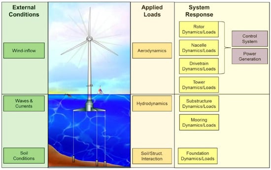
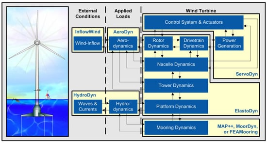
The investigation into FOWTs necessitates a comprehensive exploration of aerodynamic, structural, hydrodynamic, and mooring aspects. This intricate analysis aims to unravel the interconnected dynamics of aerodynamic forces, structural responses, hydrodynamic behaviors, and mooring system intricacies. As FOWTs stand at the forefront of renewable energy advancements, understanding the synergies and challenges within each domain becomes imperative. This multifaceted examination is pivotal for optimizing design, enhancing reliability, and maximizing the performance of FOWTs.

Aerodynamic loads are conventionally assessed using the BEM theory, a method combining momentum and blade element theories. Despite its efficiency in computation, BEM theory relies on assumptions such as rotor discretization as annuli, neglecting of root and tip losses, and consideration of steady flow. To enhance accuracy, correction models are introduced, addressing issues like hub and root losses. The BEM theory, while widely employed, requires further investigation, especially for FOWTs facing complex inflow wind conditions due to platform motions.

The structural integrity of wind turbine blades is modelled using either the 3D FEM or the 1D Equilibrium Beam Model (EBM). While 3D FEM offers precise deformation predictions through shell or solid elements, it incurs high computational costs. The widely used FEM approach discretizes structures into finite elements, applied predominantly to slender bodies using beam theory. The 1D EBM efficiently models wind turbine blade structures, categorized into linear and nonlinear beam models. Nonlinear models, such as the Geometrically Exact Beam Theory (GEBT), address geometrically nonlinear characteristics, ensuring suitability for analyzing large deformations. Discretization methods like modal approach, multibody dynamics (MBD), and 1D FEM provide options, each with its own trade-offs.
For hydrodynamic performance, FOWTs commonly utilize the ME, the PF method, and CFD. While ME lacks considerations for floating platform effects on incident wave fields, CFD captures more physical flow mechanisms, offering increased accuracy. Hydrodynamic modelling ranges from linear to nonlinear, with nonlinear methods proving more accurate but computationally expensive. Consideration of nonlinear effects is crucial for accurate modelling and involves factors like incoming wave characteristics and the hydrodynamic body. Various methods, including the Froude–Krylov force, quadratic transfer function (QTF), and Newman’s approximation, address nonlinear loads. The choice between frequency-domain and time-domain modelling depends on the trade-off between computational efficiency and accuracy, with the Cummins equation providing a framework for the latter [72].
Mooring systems are analyzed using static, quasi-static, and dynamic methods. Static methods consider constant loads, while quasi-static methods assume uniform and linear motion between static positions. Dynamic methods, including lumped-mass models, FEM, and finite difference (FD) models, account for large displacements and inertial effects. Lumped-mass models are computationally simpler, assuming that mooring lines consist of masses connected by springs. FEM and FD models offer high-fidelity solutions by discretizing the mooring line into small elements.
For the design process of an FOWT prototype at an earlier stage, a variety of numerical approaches and software programs are available. A novel design is often produced as a numerical model, which is subsequently tested in a lab setting at model scales. Designers of FOWT technology may, however, be trying to employ high-fidelity numerical tools in an effort to lessen reliance on expensive and time-consuming physical testing as well as reduce the uncertainty of simpler numerical models. L
Overall, numerical models may be divided into three categories [4][72]: low-fidelity, mid-fidelity, and high-fidelity. As fidelity increases, larger computational resources are demanded, thus leading to a reduction in computational efficiency. For sizing analysis and optimization at the first stage of FOWT design, low-fidelity models are typically employed. In order to analyze loads on FOWTs under operational and extreme scenarios, following the original design stage, mid-fidelity models or engineering-level tools are utilized. In the last stages of design, high-fidelity models are frequently utilized for thorough studies, particularly to precisely determine stresses on the structure. Figure 4 outlines the computational efficiency of various modelling approaches commonly applied to FOWTs.
Figure 4. Compromise between fidelity and computational performance for the most popular numerical models used on an FOWT [72].

References

  1. Haghshenas, A.; Hasan, A.; Osen, O.; Mikalsen, E.T. Predictive digital twin for offshore wind farms. Energy Inform. 2023, 6, 1.
  2. Mei, D. A Race to the Top: China 2023; Technical Report; Global Energy Monitor: California, CA, USA, 2023.
  3. Christopher, T.R.; Goldstein, M.; Williams, M.; Carter, A. The Road to 30 Gigawatts: Key Actions to Scale an Offshore Wind Industry in the United States; Technical Report; Center for American Progress: Washington, DC, USA, 2022.
  4. Otter, A.; Murphy, J.; Pakrashi, V.; Robertson, A.; Desmond, C. A review of modelling techniques for floating offshore wind turbines. Wind Energy 2022, 25, 831–857.
  5. Robertson, A.; Jonkman, J.; Vorpahl, F.; Popko, W.; Qvist, J.; Frøyd, L.; Chen, X.; Azcona, J.; Uzunoglu, E.; Soares, C.G.; et al. Offshore code comparison collaboration continuation within IEA wind task 30: Phase II results regarding a floating semisubmersible wind system. In Proceedings of the International Conference on Offshore Mechanics and Arctic Engineering—OMAE, San Francisco, CA, USA, 8–13 June 2014; Volume 45547, p. V09BT09A012.
  6. Sayed, M.; Klein, L.; Lutz, T.; Krämer, E. The impact of the aerodynamic model fidelity on the aeroelastic response of a multi-megawatt wind turbine. Renew. Energy 2019, 140, 304–318.
  7. Riziotis, V.A.; Voutsinas, S.G.; Politis, E.S.; Chaviaropoulos, P.K.; Hansen, A.M.; Madsen, H.A.; Rasmussen, F. Identification of structural non-linearities due to large deflections on a 5 MW wind turbine blade. In Proceedings of the Scientific Proceedings, Brussels, Belgium, 22–24 September 2008; pp. 9–14.
  8. Jeong, M.S.; Yoo, S.J.; Lee, I. Aeroelastic Analysis for Large Wind Turbine Rotor Blades. In Proceedings of the 52nd AIAA/ASME/ASCE/AHS/ASC Structures, Structural Dynamics and Materials Conference, Denver, CO, USA, 4–7 April 2011.
  9. Wang, L.; Liu, X.; Kolios, A. State of the art in the aeroelasticity of wind turbine blades: Aeroelastic modelling. Renew. Sustain. Energy Rev. 2016, 64, 195–210.
  10. Jonkman, J.M.; Musial, W. Offshore Code Comparison Collaboration (OC3) for IEA Wind Task 23 Offshore Wind Technology and Deployment; Technical Report; National Renewable Energy Laboratory: Golden, CO, USA, 2010.
  11. Popko, W.; Vorpahl, F.; Zuga, A.; Kohlmeier, M.; Jonkman, J.; Robertson, A.; Larsen, T.J.; Yde, A.; Sætertrø, K.; Okstad, K.M.; et al. Offshore Code Comparison Collaboration Continuation (OC4), Phase 1—Results of Coupled Simulations of an Offshore Wind Turbine with Jacket Support Structure. In ISOPE International Ocean and Polar Engineering Conference; ISOPE: Rhodes, Greece, 2012.
  12. Robertson, A.; Jonkman, J.M.; Musial, W.; Vorphal, F.; Popko, W. Offshore Code Comparison Collaboration, Continuation: Phase II Results of a Floating Semisubmersible Wind System. In Proceedings of the Roceedings, EWEA Offshore, Frankfurt, Germany, 19–21 November 2013.
  13. Robertson, A.N.; Wendt, F.F.; Jonkman, J.M.; Popko, W.; Vorpahl, F.; Stansberg, C.T.; Bachynski, E.E.; Bayati, I.; Beyer, F.; de Vaal, J.B.; et al. OC5 Project Phase I: Validation of Hydrodynamic Loading on a Fixed Cylinder. In ISOPE International Ocean and Polar Engineering Conference; ISOPE: Mountain View, CA, USA, 2015.
  14. Robertson, A.N.; Wendt, F.; Jonkman, J.M.; Popko, W.; Dagher, H.; Gueydon, S.; Qvist, J.; Vittori, F.; Azcona, J.; Uzunoglu, E.; et al. OC5 Project Phase II: Validation of Global Loads of the DeepCwind Floating Semisubmersible Wind Turbine. Energy Procedia 2017, 137, 38–57.
  15. Robertson, A.N.; Wendt, F.; Jonkman, J.M.; Popko, W.; Borg, M.; Bredmose, H.; Schlutter, F.; Qvist, J.; Bergua, R.; Harries, R.; et al. OC5 Project Phase Ib: Validation of Hydrodynamic Loading on a Fixed, Flexible Cylinder for Offshore Wind Applications. Energy Procedia 2016, 94, 82–101.
  16. Bergua, R.; Robertson, A.; Jonkman, J.; Branlard, E.; Fontanella, A.; Belloli, M.; Schito, P.; Zasso, A.; Persico, G.; Sanvito, A.; et al. OC6 project Phase III: Validation of the aerodynamic loading on a wind turbine rotor undergoing large motion caused by a floating support structure. Wind Energy Sci. 2023, 8, 465–485.
  17. Davidson, J.; Ringwood, J. Mathematical Modelling of Mooring Systems for Wave Energy Converters—A Review. Energies 2017, 10, 666.
  18. Masciola, M.; Jonkman, J.; Robertson, A. Extending the Capabilities of the Mooring Analysis Program: A Survey of Dynamic Mooring Line Theories for Integration Into FAST. In Proceedings of the Volume 9A: Ocean Renewable Energy, San Francisco, CA, USA, 8–13 June 2014.
  19. Walton, T.S.; Polachek, H. Calculation of transient motion of submerged cables. Math. Comput. 1960, 14, 27–46.
  20. Jonkman, J.; Butterfield, S.; Musial, W.; Scott, G. Definition of a 5-MW Reference Wind Turbine for Offshore System Development; Technical Report; National Renewable Energy Laboratory (NREL): Golden, CO, USA, 2009.
  21. Jonkman, J.M.; Wright, A.D.; Hayman, G.J.; Robertson, A.N. Full-System Linearization for Floating Offshore Wind Turbines in OpenFAST. In Proceedings of the ASME 2018 1st International Offshore Wind Technical Conference, San Francisco, CA, USA, 4–7 November 2018.
  22. Jonkman, J.M. Dynamics of offshore floating wind turbines-model development and verification. Wind Energy 2009, 12, 459–492.
  23. Arramounet, V.; de Winter, C.; Maljaars, N.; Girardin, S.; Robic, H. Development of coupling module between BHawC aeroelastic software and OrcaFlex for coupled dynamic analysis of floating wind turbines. J. Phys. Conf. Ser. 2019, 1356, 012007.
  24. Masciola, M.; Robertson, A.; Jonkman, J.; Coulling, A.; Goupee, A. Assessment of the Importance of Mooring Dynamics on the Global Response of the DeepCwind Floating Semisubmersible Offshore Wind Turbine. In Proceedings of the Twenty-Third International Offshore and Polar Engineering Conference, Anchorage, AK, USA, 30 June–5 July 2013.
  25. Tran, T.T.; Kim, D.H. The coupled dynamic response computation for a semi-submersible platform of floating offshore wind turbine. J. Wind. Eng. Ind. Aerodyn. 2015, 147, 104–119.
  26. Masciola, M.; Robertson, A.; Jonkman, J.; Driscoll, F. Investigation of a FAST-OrcaFlex Coupling Module for Integrating Turbine and Mooring Dynamics of Offshore Floating Wind Turbines: Preprint. In Proceedings of the 2011 International Conference on Offshore Wind Energy and Ocean Energy, Beijing, China, 31 October–2 November 2011.
  27. Ross, A. Orcina Project 1405 Wind Turbine Validation Report; Technical Report; Orcina Ltd.: Ulverston, UK, 2018.
  28. Azcona, J.; Munduate, X.; González, L.; Nygaard, T.A. Experimental validation of a dynamic mooring lines code with tension and motion measurements of a submerged chain. Ocean Eng. 2017, 129, 415–427.
  29. Azcona, J.; Palacio, D.; Munduate, X.; González, L.; Nygaard, T.A. Impact of mooring lines dynamics on the fatigue and ultimate loads of three offshore floating wind turbines computed with IEC 61400-3 guideline. Wind Energy 2017, 20, 797–813.
  30. Jonkman, J.M. Dynamics Modeling and Loads Analysis of an Offshore Floating Wind Turbine; Technical Report; University of Colorado at Boulder: Boulder, CO, USA, 2007.
  31. Nygaard, T.A.; De Vaal, J.; Pierella, F.; Oggiano, L.; Stenbro, R. Development, Verification and Validation of 3DFloat; Aero-servo-hydro-elastic Computations of Offshore Structures. Energy Procedia 2016, 94, 425–433.
  32. Armendariz, A.J.; Munduate, X.; Nygaard, T.A.; Hoyos, M.D. Development of OPASS Code for Dynamic Simulation Mooring Lines in Contact with Seabed. In Proceedings of the EWEA Offshore 2011 Conference Proceedings, Amsterdam, The Netherlands, 29 November–1 December 2011; pp. 1–9.
  33. Hassan, G. Bladed Theory Manual Version 4.0; Technical Report; DNV Services UK Limited: Bristol, UK, 2010.
  34. Craig, R., Jr. Coupling of substructures for dynamic analyses—An overview. In Proceedings of the 41st Structures, Structural Dynamics, and Materials Conference and Exhibit, Atlanta, GA, USA, 3–6 April 2000.
  35. Beardsell, A.; Collier, W.; Han, T. Effect of linear and non-linear blade modelling techniques on simulated fatigue and extreme loads using Bladed. J. Phys. Conf. Ser. 2016, 753, 042002.
  36. Collier, W.; Milian Sanz, J. Comparison of linear and non-linear blade model predictions in Bladed to measurement data from GE 6MW wind turbine. J. Phys. Conf. Ser. 2016, 753, 082004.
  37. Larsen, T.J.; Hansen, A.M. How 2 HAWC2, the User’s Manual; Technical Report; Risø National Laboratory, Technical University of Denmark: Roskilde, Denmark, 2007.
  38. Robertson, A.N.; Gueydon, S.; Bachynski, E.; Wang, L.; Jonkman, J.; Alarcón, D.; Amet, E.; Beardsell, A.; Bonnet, P.; Boudet, B.; et al. OC6 Phase I: Investigating the underprediction of low-frequency hydrodynamic loads and responses of a floating wind turbine. J. Phys. Conf. Ser. 2020, 1618, 032033.
  39. Bellew, S.; Yde, A.; Verelst, D.R. Application of the Aero-Hydro-Elastic Model, HAWC2-WAMIT, to Offshore Data from Floating Power Plants Hybrid Wind- and Wave-Energy Test Platform, P37. In Proceedings of the 5th International Conference on Ocean Energy (ICOE), Halifax, NS, Canada, 4–6 November 2014.
  40. Pavese, C.; Wang, Q.; Kim, T.; Jonkman, J.; Sprague, M.A. HAWC2 and BeamDyn: Comparison Between Beam Structural Models for Aero-Servo-Elastic Frameworks. In Proceedings of the European Wind Energy Association Annual Conference and Exhibition 2015 (EWEA 2015), Paris, France, 17–20 November 2015.
  41. Gueydon, S.; Lindenburg, K.; Savenije, F. Coupling of Two Tools for the Simulation of Floating Wind Turbines. In Proceedings of the Volume 8: Ocean Renewable Energy, Melbourne, Australia, 11–16 June 2013.
  42. Naciri, M.; Waals, O.; de Wilde, J. Time Domain Simulations of Side-by-Side Moored Vessels: Lessons Learnt From a Benchmark Test. In Volume 1: Offshore Technology; Special Symposium on Ocean Measurements and Their Influence on Design; ASMEDC: Stamford, CT, USA, 2007; pp. 801–811.
  43. de Wilde, J.; van Dijk, A.; van den Berg, J.; Dekker, J. Direct Time Domain Downtime Assessment For LNG Operations Using Computer Cluster. In Proceedings of the Nineteenth International Offshore and Polar Engineering Conference, Osaka, Japan, 21–26 July 2009.
  44. Serraris, J.J. Time Domain Analysis for DP Simulations. Int. Conf. Offshore Mech. Arct. Eng. 2009, 43413, 595–605.
  45. Gueydon, S.; Weller, S. Study of a Floating Foundation for Wind Turbines. J. Offshore Mech. Arct. Eng. 2013, 135, 031903.
  46. Lindenburg, C. Comparison of Phatas Versions and the Wind turbine Module; Technical Report; ECN: Petten, The Netherlands, 2011.
  47. Lindenburg, C. PHATAS Release NOV-2003 and APR-2005 User’s Manual: Program for Horizontal Axis Wind Turbine Analysis and Simulation; Technical Report; ECN: Petten, The Netherlands, 2005.
  48. Liu, Y.; Li, S.; Yi, Q.; Chen, D. Developments in semi-submersible floating foundations supporting wind turbines: A comprehensive review. Renew. Sustain. Energy Rev. 2016, 60, 433–449.
  49. Myhr, A.; Nygaard, T.A. Comparison of Experimental Results and Computations for Tension-Leg-Buoy Offshore Wind Turbines. J. Ocean Wind Energy 2015, 2, 12–20.
  50. Azcona, J.; Bouchotrouch, F.; González, M.; Garciandía, J.; Munduate, X.; Kelberlau, F.; Nygaard, T.A. Aerodynamic Thrust Modelling in Wave Tank Tests of Offshore Floating Wind Turbines Using a Ducted Fan. J. Phys. Conf. Ser. 2014, 524, 012089.
  51. Pai, P. Highly Flexible Structures: Modeling, Computation, and Experimentation; American Institute of Aeronautics and Astronautics: Reston, VA, USA, 2007.
  52. Chaplin, J.R. Developments of stream-function wave theory. Coast. Eng. 1979, 3, 179–205.
  53. Lee, C.H. WAMIT Theory Manual; Technical Report; Massachusetts Institute of Technology: Cambridge, MA, USA, 1995.
  54. Babarit, A.; Delhommeau, G. Theoretical and numerical aspects of the open source BEM solver NEMOH. In Proceedings of the 11th European Wave and Tidal Energy Conference (EWTEC2015), Nantes, France, 6–11 September 2015.
  55. Det Norske Veritaswadam. SESAM User Manual Developed and Marketed; Technical Report; DNV: Bærum, Norway, 2010.
  56. Le Cunff, C.; Heurtier, J.M.; Piriou, L.; Berhault, C.; Perdrizet, T.; Teixeira, D.; Ferrer, G.; Gilloteaux, J.C. Fully Coupled Floating Wind Turbine Simulator Based on Nonlinear Finite Element Method: Part I—Methodology. In Proceedings of the Volume 8: Ocean Renewable Energy, Melbourne, Australia, 11–16 June 2013.
  57. Perdrizet, T.; Gilloteaux, J.C.; Teixeira, D.; Ferrer, G.; Piriou, L.; Cadiou, D.; Heurtier, J.M.; Le Cunff, C. Fully Coupled Floating Wind Turbine Simulator Based on Nonlinear Finite Element Method: Part II—Validation Results. In Proceedings of the Volume 8: Ocean Renewable Energy, Melbourne, Australia, 11–16 June 2013.
  58. Leroy, J.M.; Poirette, Y.; Brusselle Dupend, N.; Caleyron, F. Assessing Mechanical Stresses in Dynamic Power Cables for Floating Offshore Wind Farms. In Volume 10: Ocean Renewable Energy; American Society of Mechanical Engineers: New York, NY, USA, 2017.
  59. Ledru, R.; Le Cunff, C.; Heurtier, J.M.; Perdrizet, T.; Poirette, Y. Influence of Hydrodynamic Modeling Assumptions on Floating Wind Turbine Behaviour. In Volume 9B: Ocean Renewable Energy; American Society of Mechanical Engineers: New York, NY, USA, 2014.
  60. Evren, S.; Unel, M.; Adak, O.K.; Erbatur, K.; Aksit, M.F. Modeling and simulation of a horizontal axis Wind Turbine using S4WT. In Proceedings of the 2012 International Conference on Renewable Energy Research and Applications (ICRERA), Nagasaki, Japan, 11–14 November 2012; pp. 1–6.
  61. Prasad, C.; Chen, Q.Z.; Bruls, O.; D’Ambrosio, F.; Dimitriadis, G. Advanced aeroservoelastic modeling for horizontal axis wind turbines. In Proceedings of the 9th International Conference on Structural Dynamics, EURODYN 2014, Porto, Portugal, 30 June–2 July 2014; pp. 3097–3104.
  62. Gözcü, M.O.; Kayran, A. Investigation of the effect of bending twisting coupling on the loads in wind turbines with superelement blade definition. In Journal of Physics: Conference Series; IOP Publishing: Bristol, UK, 2014; Volume 524, p. 12040.
  63. Heege, A.; Gaull, A.; Horcas, S.G.; Bonnet, P.; Defourny, M. Experiences in controller adaptations of floating wind turbines through advanced numerical simulation. In Proceedings of the AWEA WINDPOWER 2013 Conference and Exhibition, Chicago, IL, USA, 21–22 October 2013; pp. 5–8.
  64. Digital Solutions at DNV. Sesam Feature Description; Technical Report; DNV: Bærum, Norway, 2022.
  65. Alblas, L. Fixed Offshore Wind Structure Design, What Sesam Can Do for Fixed Offshore Wind Turbine Structure Design and Analysis; Technical Report; DNV GL—Digital Solutions: Bærum, Norway, 2018.
  66. Barrera, C.; Guanche, R.; Rodríguez, Á.; Armesto, J.A.; Losada, I.J. On the importance of mooring system parametrisation for accurate floating structure designs. Mar. Struct. 2020, 72, 102765.
  67. Suzuki, H.; Shibata, H.; Fujioka, H.; Hirabayashi, S.; Ishii, K.; Kikuchi, H. Development of an Analysis Code of Rotor-Floater Coupled Response of a Floating Offshore Wind Turbine. In Proceedings of the Volume 8: Ocean Renewable Energy, Melbourne, Australia, 11–16 June 2013.
  68. Ishii, K.; Suzuki, H.; Hirabayashi, S. 2015S-OS1-7 Improvement of Accuracy of Wave Drift Force of a Floating Offshore Wind Turbine. In Conference Proceedings The Japan Society of Naval Architects and Ocean Engineers 20; The Japan Society of Naval Architects and Ocean Engineers: Tokyo, Japan, 2015; pp. 25–28.
  69. Shiohara, H.; Gonçalves, R.T.; Houtani, H.; Suzuki, H.; Schnepf, A.; Hirabayashi, S.; Carmo, L.H.S.; Nihei, Y. Numerical and experimental comparison of the wave response of a very light floating offshore wind turbine with guy wires. In International Conference on Offshore Mechanics and Arctic Engineering; American Society of Mechanical Engineers: New York, NY, USA, 2020; Volume 84317, p. V001T01A055.
  70. Suzuki, H.; Xiong, J.; do Carmo, L.H.S.; Vieira, D.P.; de Mello, P.C.; Malta, E.B.; Simos, A.N.; Hirabayashi, S.; Gonçalves, R.T. Elastic response of a light-weight floating support structure of FOWT with guywire supported tower. J. Mar. Sci. Technol. 2019, 24, 1015–1028.
  71. Hooft, J.P. Hydrodynamic Aspects of Semi-Submersible Platforms. Ph.D. Thesis, Delft University of Technology, Delft, The Netherlands, 1972.
  72. Faraggiana, E.; Giorgi, G.; Sirigu, M.; Ghigo, A.; Bracco, G.; Mattiazzo, G. A review of numerical modelling and optimisation of the floating support structure for offshore wind turbines. J. Ocean Eng. Mar. Energy 2022, 8, 433–456.
More
Information
Contributors MDPI registered users' name will be linked to their SciProfiles pages. To register with us, please refer to https://encyclopedia.pub/register : , ,
View Times: 118
Revisions: 2 times (View History)
Update Date: 30 Jan 2024
1000/1000