Your browser does not fully support modern features. Please upgrade for a smoother experience.
Submitted Successfully!
 +1 credit
Thank you for your contribution! You can also upload a video entry or images related to this topic.
For video creation, please contact our Academic Video Service.
| Version | Summary | Created by | Modification | Content Size | Created at | Operation |
|---|---|---|---|---|---|---|
| 1 | Mirela Vaduva | -- | 13279 | 2024-01-26 08:46:34 | | | |
| 2 | Camila Xu | Meta information modification | 13279 | 2024-01-26 10:03:27 | | |
Video Upload Options
We provide professional Academic Video Service to translate complex research into visually appealing presentations. Would you like to try it?
Cite
If you have any further questions, please contact Encyclopedia Editorial Office.
Văduva, M.; Burlănescu, T.; Baibarac, M. Synthesis and Vibrational Properties of Conducting Polymers Composites. Encyclopedia. Available online: https://encyclopedia.pub/entry/54393 (accessed on 21 July 2026).
Văduva M, Burlănescu T, Baibarac M. Synthesis and Vibrational Properties of Conducting Polymers Composites. Encyclopedia. Available at: https://encyclopedia.pub/entry/54393. Accessed July 21, 2026.
Văduva, Mirela, Teodora Burlănescu, Mihaela Baibarac. "Synthesis and Vibrational Properties of Conducting Polymers Composites" Encyclopedia, https://encyclopedia.pub/entry/54393 (accessed July 21, 2026).
Văduva, M., Burlănescu, T., & Baibarac, M. (2024, January 26). Synthesis and Vibrational Properties of Conducting Polymers Composites. In Encyclopedia. https://encyclopedia.pub/entry/54393
Văduva, Mirela, et al. "Synthesis and Vibrational Properties of Conducting Polymers Composites." Encyclopedia. Web. 26 January, 2024.
Copy Citation
From composites based on carbon nanotubes (CNTs) and conducting polymers (CPs) to their biggest competitor, namely composites based on graphene or graphene derivate (GD) and CPs, there are many methods of synthesis that influence the morphology and the functionalization inside the composite, making them valuable candidates for EM both inside DSSCs and in supercapacitors devices. From the combination of CPs with carbon-based materials, such as CNT and graphene or GD, the perfect network is created, and so the charge transfer takes place faster and more easily.
solar cell
functionalization
graphene
carbon nanotube
conducting polymer
composites
1. Introduction
In the context of a higher energy demand assigned to an increased population and thus an increased level of needs, together with the depletion of natural resources and environmental pollution, the focus on finding alternative sources of energy (such as green or renewable energy) has also increased. Of all the eligible sources, e.g., the energy of the sun, wind, water, and thermal waters, the first is currently attracting the most interest. If it were efficiently converted, the energy from 1 h of sunlight on the entire globe would be enough to cover the need for one year of electricity [1]. Therefore, much research has been conducted to fabricate devices for converting solar energy into electricity and, as far as possible, to store it using the same device. Currently, the conversion process is made using silicon-based solar cells, and the trend is to replace these classical devices with lower-cost materials whose high conversion efficiency is similar. One of the newly tested devices is the DSSCs. They are conventional devices built from a photo-anode and a counter electrode (CE), overlapped in a sandwich configuration, with a thin layer of electrolyte that fills the space between them. The photo-anode consists of a transparent conductive layer (TCL), which could be Indium-tin-oxide (ITO) or Fluorine-doped Tin Oxide (FTO), on which a thin layer of TiO2 is deposited and dipped in a dye solution (usually N719). The outer part is represented by the CE, usually made of Pt, deposited on a transparent conductive layer (TCL). The electrolyte is represented by an I−/I3− redox couple, mostly liquid.
DSSCs could also be bifacial, illuminated on both sides. They include a CE material with a double function, which works as a charge transfer agent and as a regenerator for the redox couple. The CE for this kind of DSSC is transparent, with illumination available from both the front and rear sides [2]. Of all DSSC components, the fundamental one used to convert the luminous energy into electric energy is represented by the photo-anode. The most common semiconductor used for this role inside DSSCs is TiO2. The mechanism inside DSSCs consists of the path followed by the solar light from TCL until the separated charge (namely the electrons) is loaded into the external circuit. When the radiation enters the transparent conductive layer (for example, TiO2) impregnated with dye, the radiation excites the dye molecules. Therefore, the dye molecules move to higher energy levels, namely the lowest unoccupied molecular orbital (LUMO), and from there, the electrons are promoted into the TiO2 conduction band (CB) and move across to the external electric circuit. When the electrons arrive at the conductive transparent electrode (TCE), they are collected and transferred to the CE, which is usually made of platinum (Pt). The dye molecules remain in an oxidized state after light exposure and regenerate by accepting an electron from the electrolyte redox couple. After that, they return to the fundamental state. This mechanism of the charge transfer inside the DSSCs device is shown in Figure 1.
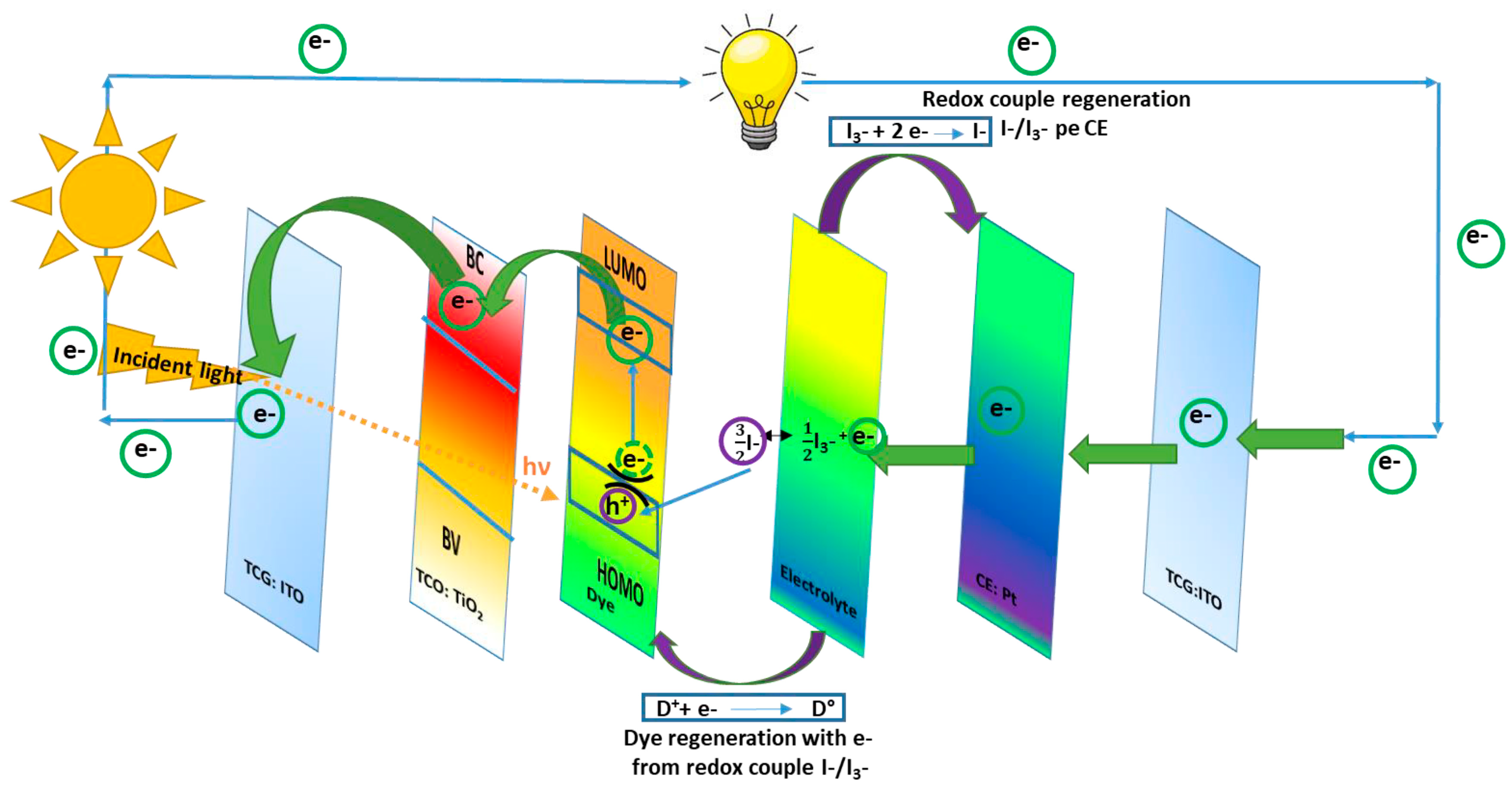
Figure 1. Mechanism inside a DSSC device.
Researchers who design and test DSSCs encounter many difficulties regarding sensitive issues about the way the components work inside the DSSCs. For example, the flexibility, long-term stability, active surface area (SA) and transparency of CE and TCL, the absorption efficiency of light, charge recombination, and so on. Amongst all of these, the main drawback of DSSCs remains the difficulty in controlling the charge recombination process, which is responsible for a major decrease in conversion efficiency. The last is the reason for being reported only on a few occasions: a conversion efficiency higher than 11% under diffuse daylight [3]. Excited dye molecules and other acceptor species from the electrolyte are involved in charge recombination processes, capturing electrons from the system and thus remaining unavailable to further interactions involved to complete the electric circuit. When using a flat surface of dye, less than 1% of incident monochromatic light is absorbed. One way of improving this performance is to increase the area of the active surface of TCL on which the dye is adsorbed, for example, by thermal sintering treatment of the TiO2 before depositing onto ITO or FTO substrates [4]. Moreover, dye molecules play an important role in the main process of the DSSC mechanism. Attached to the TiO2 surface, these absorb light, broadening the range of wavelengths to be absorbed. Then, the electrons are injected from the LUMO into the TiO2 conduction band. From this point, the electrons enter the semiconductor layer and enter the external circuit. At the same time, the oxidized dye molecules regenerate to the neutral state by reduction of the redox species in the electrolyte solution. Because it is a complete circuit, it runs without material consumption by generating electricity from sunlight. A substantial amount of this energy is unfortunately lost through the recombination process of electrons inside TiO2 with oxidized dye molecules or molecules in the electrolyte/redox medium. To increase the performance of the DSSCs, each component must be properly chosen. For example, the suitable sensitizer must fulfill several demands, such as: absorption in the full visible domain with the ability to use a higher percentage of light, affordable location of molecular orbitals (highest occupied molecular orbital (HOMO) and lowest unoccupied molecular orbital (LUMO)) to inject the electrons into the CB of the photo-anode and to help to regenerate the oxidized sensitizer from the redox electrolyte. In addition, the aggregation of the sensitizer molecules must be avoided by choosing a certain molecular structure and also the charge recombination from the TiO2/electrolyte interface. To improve the charge injection, functional groups such as carboxyl and phosphonate are desirable and the sensitizer should be also photo- and thermic-resistant providing long-term stability for the DSSCs device. Considering all of the listed demands, several types of sensitizers have been reported into the literature, including porphyrins, phtalocyanines, and metal-free organic dyes [5]. From all of these sensitizers, the biggest efficiency was reported on ruthenium and porphyrin dye with the advantage of availability and ease of structural tuning, possessing high extinction molecular coefficients [6][7]. Only a few of them reported power conversion efficiency (PCE) values higher than 9% when combining with iodide.
An issue being increasingly studied is the relationship between the electrolyte couple and the dye. It seems that the preferred redox electrolyte couple is I−/I3− due to several characteristics such as good solubility, low absorption of light, appropriate redox potential (0.35 V) providing dye rapid regeneration; this couple poses a very slow kinetic of recombination between the electrons from TiO2 and the oxidized entity of the redox couple (I3−). They do not involve into the recombination reaction by contrast other sensitizers that bound I− or I3−. Because the difference between the oxidation potential of the standard sensitizer (based on porphyrins and ruthenium, 1.1 V) and that of the redox couple (I−/I3−, 0.35 V), which means that the reduction potential of the oxidized dye is 0.75 V, this process provides the biggest potential lost from the DSSCs devices [8]. This value must be reduced at least to half of the value in order to increase the PCE to 15%. In order to move towards this, some aspects should be considered. From the regeneration of the oxidized sensitizer with I−, the reaction leads to the formation of the diiodide radical as a secondary product (I2−). Therefore, the redox potential of the I2−/I− couple should be considered when determining the force of the sensitizer regeneration because I2− leads to I3− and I− formation which is the main reason for decreasing the potential energy.
Another problem is the use of an expensive and rare CE material such as Pt, which implies the need to obtain Pt-free or low Pt content CE. Materials suitable for this position must be highly conductive, transparent, with a high rate of charge transfer, resistant to corrosion in electrolyte medium, low in cost, and available. Therefore, materials such as carbon and conducting polymers (CPs) structures or their combination thereof are eligible for this position [9]. Used alone, CPs do not perform very well as a CE inside DSSCs. In addition to their advantages, such as the conjugated structure, ease of preparation, availability and good stability, and possibility of depositing uniform thin film with a good adhesion on transparent conductive oxide (TCO), they have a relatively low conductivity. This drawback could be overcome by combining CPs with CNs for giving rise to composite materials with enhanced electrochemical and catalytic activity, able to ensure fast charge transfer from the external circuit to the electrolyte, supporting the regeneration process of the redox species. The reversible redox behavior of CPs is also a plus when it comes to contribution to a low charge transfer resistance (as in the case of polyaniline (PANI) and poly (3,4-ethylenedioxytiophene) (PEDOT)). As for the poor dispersibility of CNTs in common solvents and the tendency of GDs to overlap, leading to a graphite structure restoration, these problems are easily solved when CNTs and GDs are incorporated into the polymer matrix, so that charge transfer is accelerated and the specific active surface area is enlarged. Functionalized CNTs facilitate the formation of covalent bonds with the CPs through which the charge transfer occurs more easily and quickly; meanwhile, both GO and RGO, due to the functional groups on their surface, contribute to the uniform deposition of conductive polymers. Moreover, the charge transport is facilitated through π-π stacking between GD and CPs which creates multiple and shorter routes for both ion and electrons diffusion.
The first DSSC was made by depositing transparent layers of anatase on glass substrates, over which a thin layer of sensitizer, namely trimeric rhutenium complex, was dispersed. Using a sandwich configuration, an electrolyte thin layer containing the redox couple I−/I3− filled the space between the Ru complex/TiO2/glass and the CE made of glass covered with monolayers of Pt. At a filling factor of 0.76, the efficiency conversion was 7.9% and raised to 12% under diffuse light exposure [4].
From the entire mechanism of DSSCs, the materials used to design the CE are discussed here. The CE plays an important role, capturing the electrons from the external circuit and transporting them to the electrolyte where I3− accepts electrons and moves to I−. To complete the electric circuit, following the dye regeneration pattern, I3− accepts two electrons and changes to I−, which further regenerates through charge transfer from the CE during a reduction process (see Figure 2). The electron exchange involved in redox couple regeneration (electrons given up by I−) is fast enough to ensure efficient dye regeneration, while I3− accepts electrons from the photoanode, and the process is slow enough to allow a high carrier collection efficiency.
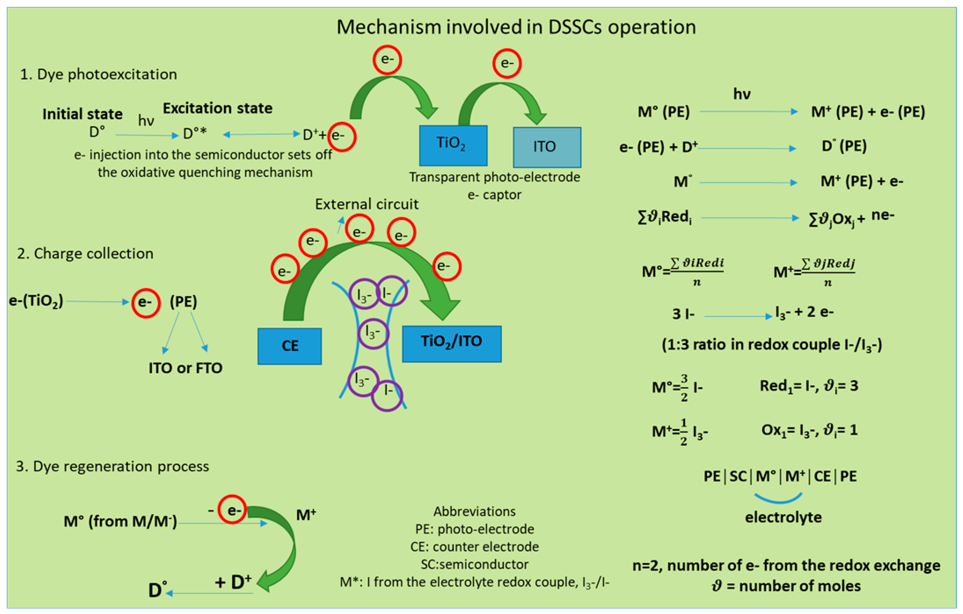
Figure 2. Mechanism of excitation and regeneration which underlines the DSSCs functionality.
The first materials tested as possible CEs were the carbon nanostructures such as graphene and CNTs, due to their high conductivity and low surface resistance, transparency, relatively fast charge transfer, availability, and affordability. Therefore, carbon nanostructures were used with this purpose from 1991 [10], when CNTs had been reported to improve the DSSCs performances, and this was followed by the use of graphene as a CE in DSSCs from 2013 [11][12][13]. In order to exceed the maxim PCE (7.88%) reached using carbon nanostructures [12], other materials were also tested, as for example their composites with CPs [13] or pristine CPs [14].
Combining CPs with CNTs, the perfect network is created and so the charge transfer takes place faster and more easily. Inside composites, different functionalizations, namely covalent or non-covalent, are formed between the functional groups attached on the surface of the CNT walls and the functional groups in the polymer backbone, which further provide the so-called synergistic effect.
2. Synthesis and Vibrational Properties of CPs-CNTs Composites
2.1. Synthesis of CPs-CNTs Composites
The main CPs which form the composites, used as CE, are poly(pyrrole) (PPy), PEDOT, and PANI. The CNTs, pristine [15] or trapped inside a gel [16], are the first carbon structures used as a CE material, replacing Pt. According to the literature, the composites based on CNTs and CPs were prepared by depositing CNTs on the substrates of the type FTO or ITO followed by: (i) chemical polymerization; (ii) electrochemical polymerization [16][17][18][19][20][21]; or other methods such as (iii) the precipitation of the already synthesized polymer [22] and (iv) the doctor blade method [23]. The one which provides good control of the thickness and uniformity of the grown layer is the electrochemical method that remains the most used of all. Before depositing the composite on a conductive glass substrate, certain preparations were necessary. Therefore, H. Li and colleagues treated an FTO substrate to improve its hydrophilicity by sonication into a mixture of ammonium hydroxide, water, and hydrogen peroxide (1:5:1 volume ratio) [24]. Then, on the already-prepared substrate, the CNTs were spin coated and then exposed to a heat treatment at 60 °C for 30 min. H. Li and co-workers have also reported preparation of PPy/CNTs composites using an in situ electro-polymerization technique. Prior to the preparation of the composite, the CNTs were treated to improve their solubility by functionalization with –COOH groups. This procedure was performed for improving the CNTs solubility in water by functionalization of the CNTs walls with –COOH functional groups [24]. Further, the composite based on CNTs and PPy was obtained from a mixture, containing 10 mM pyrrole, 20 mM sodium dodecyl sulphate (SDS), and 20 mM lithium perchlorate (LiClO4), through cyclic voltammetry (CV) [19][24]. Using the same method, namely the electrochemical synthesis, a composite with a honeycomb morphology was obtained [25]. To prepare PANI- and single-wall carbon nanotubes (SWCNTs)-based composites by electrochemical synthesis, Bumika, M. and colleagues used sodium dodecylbenzene sulfonate (SDBS) to obtain a CNTs dispersion of carboxyl-functionalized SWCNTs (SWCNTs-COOH) with a weight ratio of SDBS: SWCNTs–COOH equal to 9:2, in 0.5 M H2SO4 solution [20]. The resultant dispersion was then mixed with a second mixture prepared from ZnO (6 wt.%) and 0.25 M aniline (ANI) solution and deposited on FTO through CV, in a three-electrode configuration cell, between −0.62 V and +1.2 V [20].
The second most used method to synthesize composites is the chemical polymerization. X. Liu and co-workers reported this method for the synthesis of CE composites materials based on three different CPs precursors and CNTs [16]. The chosen monomers were polymerized in the presence of CNTs embedded in the polyacrylic gel matrix (PAA). The process of incorporating CNTs into gel was conducted according to a protocol reported by Li and co-workers [26][27]. According to this protocol, 15 mL of CNTs aqueous homogenous dispersion was mixed with 1 g of hexadecyl trimethyl ammonium bromide and stirred at 80 °C for 10 min. Afterwards, 10 g of acrylic acid (AA) and 0.005 g of N, N-methylenebisacrylamide were added and stirred until homogenized. When all components were very well mixed, the polymerization reaction was started with potassium peroxydisulfate (KPS) (0.08 g). The reaction was carried out for 2 h, under vigorous stirring at 80 °C. The final product was freeze-dried for 72 h. After synthesizing the CNTs-PAA gel, pieces of it were dipped into solution of monomers, of ANI, 3,4-ethylenedioxythophene (EDOT), and pyrrole (Py), for 24 h, at room temperature so that the monomers could swell inside the gel. After dispersion of the swollen monomers inside CNT gels in KPS solution (0.03 M), an internal polymerization process took place with the formation of the corresponding conducting polymers. The final products were poly (AA-co-CNTs-Py), poly (AA-co-CNTs-co-ANI), and poly (AA-co-CNTs-co-EDOT) gel. As a part of the DSSCs device, the as-prepared composite gels were soaked into a liquid electrolyte containing tetrabutylammonium iodide, tetramethylammonium iodide, I2, tetraethylammonium iodide, LiI, and tetrabuthylammonium iodide in N-methyl-2-pyrrolidone and acetonitrile (1:4 volume percentage) [16].
Other methods, rather physical methods, used to prepare a composite based on CPs and CNTs were reported by Abdul Almohsin, S.M. and colleagues [22] and respectively by Dowa, C. et al. [23], using the precipitation of CPs on top of CNTs/FTO and, respectively, the doctor blade method.
According to the last method, PANI and CNTs were dispersed in m-cresol at a 100 mg/mL concentration until a viscous paste was obtained. During mixing PANI and CNTs, a few drops of terpineol and ethyl cellulose (15 wt.% in ethanol) were added and the whole mixture was magnetically stirred for 3 h. The resultant paste was spread over an FTO-coated substrate by the doctor blade coating method. The coated layer was maintained at room temperature to dry and then thermally treated at 400 °C for half an hour. M-cresol interacts with the polymer chains and act as a dopant to PANI and, at the same time, it is a good dispersing agent for high CNT content. Mixing CNTs with m-cresol produces a thick, viscous solution that helps to deposit a more uniform and homogenous layer of CNTs on a substrate.
Composite materials used as CE after being deposited on FTO substrate show different features depending on the type of CPs, the carbon nanostructures inside the composite, the interaction between the two components of which is directly related to the type of synthesis. Moreover, when using carbon nanostructured inside the composites, there are some aspects regarding their functionalization to be eligible for further interaction with the CPs. Then, considering all these aspects, the vibrational properties will be further discussed, investigated using mainly Raman and FTIR spectroscopy and some parameters concerning the DSSCs electro-catalytic activity. Certain aspects will be followed in order to understand the interaction between the composite components and its influence on the light conversion efficiency, according to the information provided by the selected papers used in this work.
2.2. Vibrational Properties of CPs/CNTs
Prepared by in situ chemical polymerization of PAA–CNT gel soaked into monomer solution, poly (AA-co-CNTs-Py) was analyzed through IR spectroscopy and the recorded spectra revealed specific absorption bands assigned to Py, CNT, and PAA. According to Table 1 (inserted below) the specific bands were assigned to PPy ring vibrations (1547 and 1038 cm−1), N-H in-plane deformation [28][29], N-C stretching vibrations, and C-H band stretching vibrations (1175 and 910 cm−1), respectively. Meanwhile the band situated at 3421 cm−1 corresponds to the stretching vibration of the OH functional group of the PAA polymer, while the bands assigned to CNT are those located at 1450, 620, 1400, and 2945 cm−1 corresponding to wagging vibration, C-H out-of-plane vibration, the last two being characteristic of the methyl functional group and sp3 hybridized carbon atom. Other bands are assigned to the external functional group attached to the CNTs walls, such as for example: for the carboxyl group, specifically the bending vibration of C=O bond in –COOH represented by the IR band at 1685 cm−1, the C-O-C stretching vibration and the assigned band at 1140 cm−1 [30][31], the C=O stretching vibration and the bending vibration of the –OH bond in –COOH at 1719 and 1348 cm−1. For a better understanding of all interactions between PPy and grafted CNTs with carboxyl groups, the IR vibrational structure of this composite is shown in Figure 3.
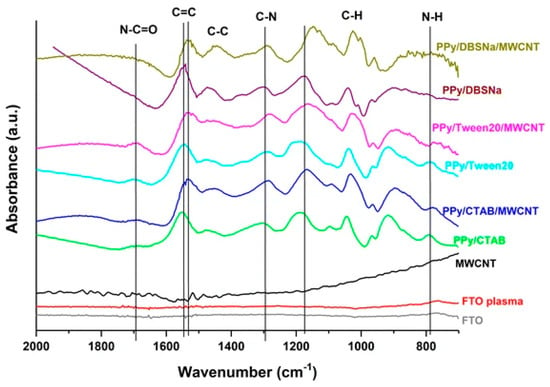
Figure 3. FTIR spectra of FTO, FTO plasma, MWCNT, PPy/CTAB, PPy/CTAB/MWCNT, PPy/Tween20, PPy/Tween20/MWCNT PPy/DBSNa, and PPy/DBSNa/MWCNT, where MWCNTs are non-covalently functionalized with PPy [17].
According to X. Liu et al., gel electrolytes with CNTs incorporated have a dual function inside DSSCs: to enlarge the SA, as well as increase conductivity, providing a high catalytic activity and thus contributing to short-circuit density (Jsc) enhancement [16].
Changes in the IR absorption bands of PPy have been reported in the case of the IR spectra of the composite based on PPy and CNTs, synthesized through the electropolymerization of Py in the presence of CNTs [17]. A shift to lower wavenumbers of the band located at 1530–1560 cm−1 and assigned to the C=C/C-C stretching vibration of the PPy chains indicates a higher delocalization length in the polyconjugated system [32], which means longer polymeric chains are formed in the presence of CNTs, because of a non-covalent interaction between the π-π bonds of PPy and CNT (see Figure 3).
The presence of functionalized multi-wall carbon nanotubes (MWCNTs) into the PPy matrix is revealed through an enhanced intensity of peaks and a little shift, as a consequence of the interaction between carboxyl group from MWCNTs and functional groups from PPy creating a network where electrons are transferred from one compound to the other. Further, inside the nanocomposite based on PPy and functionalized multi walled CNTs (FMWCNTs), the bond associated with C-H, C-C, and N-H vibration becomes weaker and instead the C-N bond becomes stronger. The fact that MWCNTs are wrapped in PPy is confirmed through the disappearance of IR bands, such as for example the IR bands located at 1198 and 2879 cm−1, present in acid-treated MWCNTs [33][34]. As formed PPy-FMWCNTs have a better conductivity than pristine PPy, 250 S/cm vs. 35 S/cm due to a higher localization length of 10 nm vs. 1.55 nm for FMWCNTs, the value improved as a result of the large arrangement of the π conjugated structure [21].
The electrostatic interaction which takes place between the quinoid rings of both components, one donor (PPy) and the other e− acceptor (MWCNTs), determined a fast movement of charges inside the composite enhancing its conductivity. Morphologically, the PPy layer is porous and uniformly dispersed on the electrode surface, and embedded on FMWCNTs which creates a transport network for electrons that enhances the cathodic reaction of the redox couple I3−/I− [35].
According to He and co-workers, using in situ chemical polymerization, CNTs are covalently bond to PPy, forming a new composite [36] (Figure 4) with a covalent bond between the nitrogen atom in the pyrrole ring and the sp2-hybridized carbon atom in the CNT network. The best results have been recorded for an optimum of 2 wt.% SWCNTs on which values of 8.3 PCE have been reported. Compared to pristine PPy (PCE 6.3%), the improved results were assigned to the lower charge-transfer resistance (Rct) value.
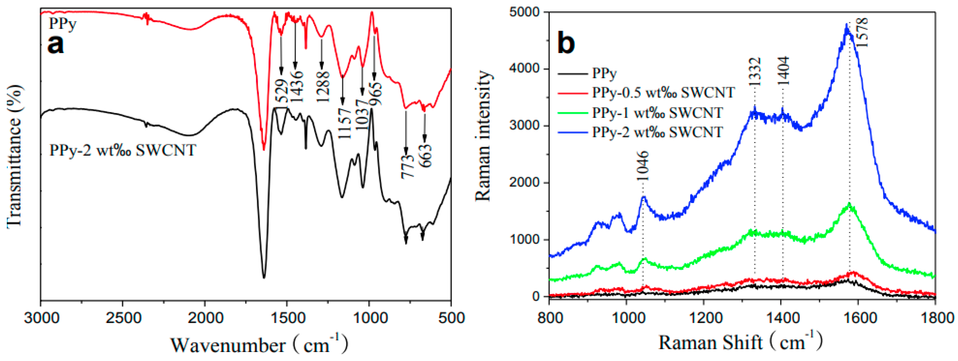
Figure 4. (a) FTIR and (b) Raman spectra of PPy and PPy-SWCNT composites, where SWCNTs are covalently functionalized with PPy [36].
In all Raman spectra of the PANI-CNTs composite, the CNT-specific lines were located at 1591 and 1334 cm−1 corresponding to the radial breathing mode (RBM) [37] and tangential mode [38] and the PANI lines located at 1581, 1052, 1083, 1330, 1370 cm−1 assigned to the vibrational modes of C=C stretching, C-H in plane deformation, and the aromatic ring stretching mode [39][40] (see Table 1 for more information). The most significant change has been recorded in the intensity of the Raman line located at 1334 cm−1 which increases with the amount of SWCNTs in the composite. The interaction between the components inside the composite was reported to be rather weak considering the lowest PL intensity band located at 520 nm [16]. The layer morphology, noted by PANI and CNT-based composites, varied from the honeycomb structure [24] to the axel sleeve structure obtained by co-polymerization [41] or a uniform film obtained by electrophoresis and CV [42].
It was already reported that the deposition of a PEDOT thin layer on the TCO substrate contributes significantly to a decrease in the surface resistance (SR) and as a direct consequence the conductivity increases. When PEDOT is prepared by the electropolymerization of EDOT, a layer of well-connected mesoporous composite is obtained on the CNTs film already cast on the TCO substrate. In this case, the CNTs play the role of template leading to porous nanostructured wires [43] but the CNTs can also be wrapped in PEDOT film by π-π coupling [44]. If another method is used, such as in situ chemical polymerization, covalent bonds are formed between PANI and CNTs, more precisely between –NH– in PANI and –C=, i.e., the sp2 hybridized carbon atom of SWCNTs, and this bond contributes significantly to the acceleration of charge transfer between composite components [45]. The CE improves with increasing CNTs loading, regardless of the chosen synthesis method [46].
Composites based on PEDOT and CNT have been reported having different morphologies, such as porous wire nanostructures deposited on a CNT template [43], or core-shells structures, where CNT is the core and PEDOT is the shell [47], using the oxidative polymerization method. It was found that, when using an aligned structure or well-ordered CNTs, it could enhance photovoltaic performance, i.e., PCE, by decreasing resistance and increasing conductivity [15]. Different from the classical CNT and CP–based composite, CNTs could be also used as a filler or matrix with different CPs. The latter has been used to solve both the problem of the poor dispersion of CNTs in solvents and to improve their electronic conductivity. Another study reported as an electromaterial (EM) in DSSCs a poly(3,4-ethylenedioxythiophene)-poly(styrenesulfonate) (PEDOT: PSS)-based composite and CNTs, where PEDOT: PSS was used as a dispersing agent of CNTs [48]. The efficiency of the composites thus prepared was lower than those reported when Pt was used as a CE (8.5%).
Inside PANI and CNT-based composites, the resultant defects generate a higher surface area, and this is supported by an enhanced intensity of the D band peak in the Raman spectrum of the composite compared with the spectrum of the CNTs, which confirms the presence of sp3-hybridized carbon atoms attached to the surface of CNTs. The value of the ID/IG ratio increases from 0.125 to 0.168 for the composite (see Figure 5) due to the increase in the number of defects at the edge of the CNTs [23].
Table 1. Main specific IR and Raman bands assigned to the components used in the synthesis of CE composite materials (PPy, PANI, PEDOT, PAA, and CNTs).
| CPs | Vibrational Modes Active in IR Spectroscopy |
Wavenumber (cm−1) | Ref. | Vibrational Modes Active in Raman Spectroscopy | Wavenumber (cm−1) | Ref. |
|---|---|---|---|---|---|---|
| PPy | Vibration of pyrrole ring ν C–H ν N–C δs N–H (1038 and 1547 cm−1) ν C=C and ν C–C, PPy ring vibrations |
700–800 910 1175, 1210 1038 1547 1530–1560 1556 |
[16][28][29][32] | - | - | - |
| PANI | δ C–H of the quinoid ring ν C–N and δ C=C ν quinoid ring and δ benzoid ring |
1133 1243 1301 1489 1564 |
[40][49][50][51] | Bipolaron and polaron bands, δ C-H, ν ring, ν C=C |
940 990 1052 1083 1330 1334 1370 1581 |
[18][39] |
| PEDOT | ν C−C or C=C of the quinoide structure and ν thiophene ring |
834 978 1187 1315 1356 1513 |
[52] | ν C-S-C bond in thiophene ring δ C-O-C bending vibration in ethylenedioxy group νas SO2 |
834 978 1187 1315 |
[52] |
| PAA | ν OH | 3421 | [16] | - | - | - |
| CNTs | γ C–H | 620 1140 1348 1400 1450 1685 1719 2945 |
[16] | RBM, E2g mode assigned to slightly disturbed graphite E2g mode of graphite wall |
1334 1591 |
[16] |
| ν C-O-C | ||||||
| δ OH from –COOH | ||||||
| ω C–H (1400 and 1450 cm−1) | ||||||
| δ C=O from –COOH (grafted to the CNTs wall) | ||||||
| ν C=O | ||||||
| ν CH3 |
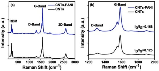
Figure 5. Raman spectra of (a) CNTs, CNTs-PANI films coated on FTO glass, and (b) a magnified version of the D and G band [23].
2.3. Performance of CPs/CNTs as CE in DSSCs
The efficiency of the presented composites varies from 1.67% [17], reported on PPy/CNTs, to 9.07% for PEDOT/CNTs [53], both composites synthesized through in-situ electropolymerization of monomers (see Table 2). Higher PCE values were obtained on composites when the dispersing agent (SDS) was used, the PCE value of 6.15% being close to that reported for Pt (6.36%) [20]. The good results were mainly attributed to the low Rct at the CE/electrolyte interface [18]. Also, very good results have been reported for structures obtained by chemical vapor deposition (CVD) of the polymer on the CNT film surface. Such an example is the subject of the study by W. Hou and co-workers, when the presence of PPy induced a PCE of 7.15 [54]. Comparing a covalent composite [36] with those in which the interaction between components is non-covalent [17], it would appear that those with a higher PCE are those in which covalent bonds are present (see Table 2).
Table 2. Synthesis and CE performance parameters (CE, FF, Jsc, and RCT) of the CNTs/CPs composites.
| Composite CPs/CNTs | Synthesis | PCE (%) | FF | Jsc (mA cm−2) | Rct (Ω × cm2) | Ref. |
|---|---|---|---|---|---|---|
| (a) CNTs/PPy (b) CNTs/PANI (c) CNTs/PEDOT |
Electrochemical synthesis | 6.82; 7.01; 7.2 | 0.69 | 13.73; 13.92; 14.11 | 1; 7.43; 7.5; 7.51 | [16] |
| MWCNT-PEDOT: PSS | Physical mixing | 6.1% | 59.8 | 12.9 | - | [18] |
| * h-PEDOT/MWCNTs | Electropolymerization | 9.07 | 0.67 | 17.09 | 0.19 | [53] |
| PPy/SDS/CNTs | Electrochemical polymerization | PPy-SDS-CNT 6.15 | PPy-SDS-CNT:58.69 | 15.47 | 0.19 | [19] |
| PPy/MWCNT/FTO | Electrochemical polymerization | 1.67% | 0.53 | 5.44 | - | [17] |
| (A) Cu-PPy-CNT (B) PPy-CNT |
Electrodeposition method | (a) 7.1% (b) 5.49 |
(a) 0.696 (b) 0.682 |
(a) 2.35 mA/cm2 (b) 10.27 |
(a) 4.31 Ω × cm2 (b) 5.29 |
[21] |
| PPy-SWCNTs | Chemical polymerization | 8.3% | 0.71 | 15.68 | 8.15 | [36] |
| PANI-SWCNTs | Electropolymerization | front ill **: 7.07% | 0.53 | 17.5 | 0.18 | [24] |
| PANI/SWCNT/ZnO nanorods | Polymer precipitation top of MWCNTs | - | - | - | - | [22] |
| PANI/SWCNT/ZnO | One-pot electrochemical synthesis | PS: 3.16 and PSZ: 3.81 | PSZ (PANI-SWCNT-ZnO): 56 | PSZ: 9.59 | PSZ: 10.10 | [20] |
* honeycomb-like structure. ** illumination.
For describing the electro-catalytic activity of the CE, there are several important parameters and associated measurements which should be considered, namely CV, electrochemical impedance spectroscopy (EIS), Tafel polarization, chrono-amperometric studies, RCT, surface layer resistance (Rs), PCE, Jsc, filler factor (FF), and so on. The information discussed in this section depends on the information provided by the papers selected for this study.
In addition, the photovoltaic performance of DSSCs is investigated though I-V measurements. EIS studies are performed to describe the charge transfer kinetic of the electrochemical system, more precisely the electro-catalytic activity of the CE versus the reduction process of the electrolyte, in a symmetric cell system. Using the Nyquist plot, the RCT could be determined from the graphic which describes the charge mobility between the CE and the electrolyte. Specifically, the RCT value depends on the diameter of the semicircle corresponding to the chemical capacitance (CPE) at the electrode/electrolyte interface. The semicircle on the right, located in the low frequencies area, represents the Nernst diffusion impedance (W), a measure of the electrolyte that controls the diffusion of the I3−/I− redox species to the CE, in addition a lower value of RCT indicating a faster charge transfer inside the symmetric cell. RCT varies inversely with the Jsc recorded for I3− to I− reduction process on CE. From the cyclic voltammograms recorded using electrodes of the type PEDOT/ITO, CNTs/ITO, ITO, and PEDOT-SWCNTs/ITO, the synergic effect of both components is presented. While on the pristine ITO electrode the redox peaks are missing, in the case of PEDOT/ITO, there are two peaks that are broad and far apart, and less reversible than those found on PEDOT-SWCNTs/ITO, revealing the idea that PEDOT alone could not be as efficient and that this could be extended to replacing the ITO substrate with SWCNTs as a better one for improved catalytic response. Another evidence that PEDOT and SWCNTS go well together is the efficiency value which is double in the case of PEDOT-SWCNTs than for pristine SWCNTs. A high filling factor and I-V measurement confirm the good catalytic performance of PEDOT-SWCNTs composites used as a CE for DSSCs devices [55].
According to Abdul Almohsin, S.M., the composites based on PANI and SWCNTs, prepared by one-pot electrochemical synthesis [22], present a much lower RCT value than the pristine PANI (95 vs. 845 Ω), proving the contribution of the SWCNTs to the enhancement of charge transfer within the composite. The morphology of the CE films also contributes to the photoelectric performance of the DSSCs by influencing their transmittance and diffuse reflectance properties. The latter two are maintained at high values even when CNTs have been added [53]. The high conductivity of SWCNTs together with the layer morphology [24][53] doubled the photoelectric performances of the CE in DSSCs. This is the case of composites based on PPy and CNTs with a honeycomb-like structure [20]. The presence of a surfactant within the EM composite can influence its catalytic performance [17][19]. The surfactant induces an enhancement of the interactions between the polymer chains, increases the stability, and enhances the electropolymerization current, together with providing an easy charge exchange between the electrolytic medium and the polymers [56].
Benefiting from a morphology of the porous structure resulting from well-separated fibers formed from PANI-coated CNTs, as a result of the doctor blade synthesis method, the PCE value of CNTs-PANI (6.67%) almost reaches the value reported for Pt (7.70%) [23]. The low performance of this CE EM could be due to the thick catalytic layer with 6% PANI content, which provides a higher total internal resistance, but also the opaque nature that prevents the light reflection effect [43].
In terms of DSSCs performance, the external quantum efficiency (EQE), also called the incident monochromatic photon-to-electron conversion efficiency (IPCE), is an essential characterization method.
IPCE spectra showed a broad band in the 250–800 nm region, with a maximum value at 535 nm. From Figure 6b, it can be seen that the IPCE curves of DSSCs increase as a function of EM in the order CNTs < CNTs-PANI < Pt. The reported results obtained in the IPCE curves are well correlated with the JV curves (Figure 6a). Despite the fact that the performance of CNTs-PANI CE materials does not exceed that of the Pt electrode, CE composites based on CNTs and CPs could be a good alternative to replace Pt, at least economically.
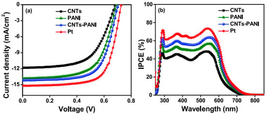
Figure 6. (a) JV characteristics of Ems, namely CNTs, PANI, CNTs-PANI, and Pt and (b) the incident photon to current conversion efficiency (IPCE) spectra of CNTs and CNTs-PANI-based DSSCs for 10 devices [23].
3. Synthesis and Vibrational Properties of CPs-GD Composites
3.1. Synthesis of CPs-GD Composites
After the incorporation of graphene into PEDOT, the electrochemical activity is reported as improved and the charge transport is much faster through the composite film [57]. The reduction potential of the redox couple is shifted towards negative potentials, compared to a Pt/ITO CE, which means it still has a higher resistance. When prepared by CVD, the characteristic parameters of the graphene layer are superior to those prepared using other techniques. For example, the I2D/IG ratio is about 2.5 while the D band has a low intensity and the transparency of the monolayer compared to four layers is of 97.4% vs. 90.6%, at λ = 550 nm.
Moving from mechanically mixing graphene [58][59] and CP to the deposition of a polymeric film on top of the graphene, ultimately by in situ polymerization [60][61], many methods of synthesizing composite that were designed as CE materials have been reported. Together with the organic sol-gel route for the synthesis of aerogel structures [62], all reported methods have in common the individual deposition of the polymer and the graphene/GD layer; this means that the resulting composite material is closer to a sandwich structure more than to a bulk one for which the polymerization process takes place simultaneously [63][64][65].
For the PANI/graphene composite, the reaction mixture was prepared by combining a solution of monomer, prepared from 1.2 mmoles of ANI dissolved in 50 mL acid solution (0.4 M HCl) with 50 mL of a second solution made by solubilizing 0.41 mmol ammonium persulphate (APS), as a polymerization initiator, in 0.4 M HCl. The mix of both solutions was poured into a previously cooled bath, into which the graphene-modified electrode was already been introduced, and left there for 30 min, and then immersed in a 1 M HCl solution until complete conversion occurred from polyaniline-emeraldine base (PANI-EB) to polyaniline-emeraldine salt (PANI-ES) [66]. Brought together, the pristine graphene, difficult to incorporate into a polymer matrix, and the PANI difficult to adhere to the FTO substrate also came with advantages such as providing appropriate support for nucleation and polymerization, due to the presence of GO, and the homogenous RGO dispersion provided by PANI, making them a winning combination for a CE material. At the interface of both PANI and RGO, interactions such as π-stacking, hydrogen bonding, electrostatic, and donor–acceptor take place [67]. In an acidic medium, between PANI, in the form of emeraldine salt (characterized by a polaron energetic state) and RGO with a negative charge storage capacity, a transfer of weakly bound electrons takes place, which is a good source of electrons for the regenerating of the electrolytic redox couple I−/I3−.
A special method for preparing aerogels composite structure was reported recently by Mohan, K. et al. The conversion into a PANI/RGO aerogel (PANI/RGOA) composite was made by preparing two dispersions of GO and, respectively, PANI nanotube (PANI NT), in deionized water, of 10 mg/mL in each suspension. In the preparation of RGOA, GO aqueous suspension was mixed with resorcinol, formaldehyde, and sodium carbonate (0.337, 0.362 g and, respectively, 1.6 mg) and stirred for 30 min. The two suspensions were then mixed in 100 mL flasks, sealed, and maintained at 85 °C for 3 days to obtain PANI NT/RGO aerogels, washed with deionized water, and freeze-dried for 24 h. At the end of the process, the aerogel pastes were deposited through the doctor blade method onto FTO glass and heated to 80 °C to obtain the CE. The aerogel pastes contained 10 mg of PANI/RGO aerogel dispersed in 0.5 mL Nafion solution [62]. The PANI/RGO aerogel prepared via the organic sol-gel route presented a high surface area and excellent catalytic activity towards the reduction of I−/I3− in electrolyte [62]. PANI/GD composites have been also synthesized using economical methods such as the spray method [68]. First, the RGO layer was deposited on the FTO surface from 0.015 g of RGO mixed with 2.5 mL of acetic acid and 0.02 Triton X-100, and finally 100 mL of ethanol was added, and the entire mixture was ultrasonicated for 1 h. The resulted mixture was sprayed on the FTO surface, thermally annealed at 100 °C, and finally sintered at 250 °C. Then, 0.015 g RGO powder was mixed with an appropriate amount of PANI, 2.5 mL acetic acid, and binding agent Triton X-100, for 10 min; after that 1 mL dispersion of SnO2 in ethanol was added, followed by pouring 100 mL of ethanol. The entire mixture was then sonicated for 1 h and at the end, PANI/RGO/SnO2 was obtained. The suspension was sprayed onto a heated FTO support and sintered at 250 °C. The resulting composite has a porous structure, with many interconnections and pathways between components that provide an enhanced electrocatalytic effect in the triiodide ion (I3−) reduction reaction at the CE. The porosity of the composite increase when SnO2 was introduced into the RGO structure provided a better adhesion for the interaction with CP. Comparing the PANI/graphene composite with the PPy/graphene composite, the way of synthesizing is very similar, so the composites materials were obtained by mixing the already-prepared polymer with the graphene precursor. Therefore, PPy was first obtained from mixing the aqueous solution of polyvinyl alcohol (PVOH) with ferric chloride, followed by the addition of pyrrole monomer, and the mixture was stirred in an ice bath for 4 h to obtain powder in suspension. The resulting powder was then mixed with graphene oxide (GO) powder in 10 mL of water. To this mixture, 0.088 g ascorbic acid was added, with the task of playing two roles, binder and reducing agent. The suspension was then deposited onto the FTO substrate using the doctor blade method [61]. In addition, the mechanical mixing method is not to be neglected in the preparation of PEDOT: PSS and graphene-based composites [58][59]. Using ultrasonication to mix PEDOT: PSS with nanoporous RGO helped to exfoliate RGO and insert a thin layer of graphene into the PEDOT: PSS matrix [59].
3.2. Vibrational Properties of CPs-GD
Regarding the vibrational properties of CP and graphene-based composites, leaving aside the characteristics of the IR and Raman spectra signature of each PANI, PPy, PEDOT, PEDOT: PSS, graphene, GO, and RGO, which will be also mentioned here in Table 3 inserted below, some changes were observed in their composite spectra that are relevant to be discussed here in terms of the type of functionalization between the two components inside the composites.
For further clarification, each individual polymer was discussed as follows: in the case of PANI, the active conductive form of PANI is ES, and after preparation and conversion it is important to check the presence of PANI-ES. Therefore, the conversion of PANI-EB to PANI-ES is confirmed by the presence of N in a protonated state. The distribution of N states shows the existence of pyridinic and pyrolic nitrogen [69].
Further evidence for the conversion from PANI-EB to PANI-ES is represented by the presence of the absorption band located at 330 nm, assigned to the π-π* electronic transition of the benzoid ring, which is blue-shifted from 330 nm (for bulk PANI) to 313 nm, a minor peak at 347 nm corresponding to π-π* electronic transition of PANI-EB, and the split peak from 360 nm assigned to the localized polaron-π* transition from the conductive form of PANI, the emeraldine salt. Another two bands located at 366 nm and 434 nm, corresponding to localized polarons and π-polaron transition, also confirm the formation of PANI-ES [70]. In addition, the main band characteristic of the insulating form of PANI-EB, located at 630 nm, assigned to local charge transfer between the quinoid ring and the adjacent imine-phenyl-amine is absent [71]. Further, for the PANI/RGO aerogel composite, both the Raman and FTIR spectra reveal the presence of both PANI and RGO [62] (see Figure 7), the bands from the spectra being overlapped, and the main change in their profile when analyzing the PANI/RGO spectrum seems to be the change in the main bands profile, described by an enhancement in their intensity rather than the appearance of new bands. The aerogel composite prepared by introducing PANI in GO suspension also presents new bands in the FTIR absorption spectrum, located at 3421, 1304, 1113, and 812 cm−1, assigned to stretching vibration of N-H bond, stretching vibration of C-N bond, stretching vibration of N-Q-N, and asymmetric stretching vibration of 1,4 double replaced benzoid ring.
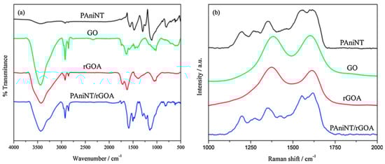
Figure 7. FTIR (a) and Raman (b) spectra of PANI NT, GO, RGOA, and PANI NT/RGOA [62].
The conversion of GO into RGO during synthesis was confirmed by the disappearance of the bands associated with the groups with oxygen and a decrease in intensity of the bands located at 3440, 1736, and 1402 cm−1, as revealed from the PANI/RGO FTIR spectrum. Complementary to the FTIR spectrum, the Raman spectra reveal the bands specific to PANI, located at 1620, 1550, 1350, and 1200 cm−1, associated with C-C vibration, imine vibration C=N, semi-quinoid polaronic vibration C-N+, and the in-plane bending vibration of the C-H bond corresponding to the quinoid ring, respectively [72]. The bands specific to GO and RGO, the G and D bands, are located at 1608 and 1360–1385 cm−1, respectively. H. Mohan and co-workers reported an enhancement of the IG/ID ratio during aerogel formation, namely from 0.98 to 1.5, due to the conversion of GO to RGO associated with a decrease in the number of the oxygen groups from the surface, which also leads to a retrained sp2 domain surface. Nevertheless, the vibrational spectrum of PANI/RGOA does not differ much from the PANI spectrum, the main change consists of a decrease in intensity of the band located at 1620 cm−1, assigned to the presence of RGOA inside the composite structure. From the morphology point of view, the tubular fiber structure of PANI is weaving with the wrinkled paper appearance of the graphene compound, where there in not graphene or PANI. PANI is attached at the graphene foil surface without aggregation. Inside the aerogel structure, PANI interacts with RGO through π-π stacking at the basal plane level.
The non-covalent interaction between PANI and RGO, exemplified according to Figure 8, is described with the help of the red shift of the IR band, related to the PANI matrix, located at 1560, 1480, 1295, 1241, 1125, and 797 cm−1, as a consequence of a π-π interaction and hydrogen bonding between the basal planes of RGO and the PANI backbone [73]. Due to the strong interaction of RGO hydrophobic planes and PANI backbone [73][74], the Raman lines of RGO/PANI are shifted towards low wavenumbers. The peaks corresponding to the PANI signature have been red-shifted due to π-π interaction and hydrogen bonding between the basal planes of RGO and the PANI backbone [73], describing the non-covalent interaction between the components (PANI-RGO); a shift towards low wavenumbers has been also observed in the Raman spectra of RGO/SnO2/PANI as a consequence of the strong interaction of RGO hydrophobic planes and the PANI backbone [73][74].
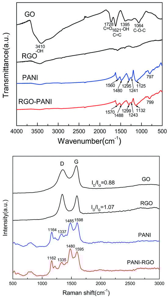
Figure 8. FT-IR and Raman spectra of GO, RGO, PANI, and PANI-RGO nanocomposites [73].
When analyzing the composite based on PPy and GD, it seems that the CP is the prevalent component of the composite as in the cases of the PANI-based composite described above. Thus, the signal of PPy prevails on the spectrum of the composite [61]: in the Raman spectra of the composite with RGO, two main bands were revealed, located at 1341 and 1559 cm−1 and assigned to the stretching vibrations of the pyrrole ring and C=C bond from Py, respectively. When added to RGO, the main PPy bands shifts to 1350 and 1590 cm−1 upon increasing the amount of RGO as a consequence of the overlaps with the D and G bands of RGO [75]. Comparing the aerogel carbonic structures, the polymer gel with the classic shape of composite used as a CE material and electrolytes for DSSCs, the first attract more interest. For example, from the carbonic aerogel category, graphene aerogels have a mesoporous three-dimensional structure due to the interconnected graphene sheets, a structure which provide special properties such as a high electric conductivity [76] and large volume of the pores. These features facilitate the charge transport and the mass transfer of the redox species. Therefore, their special structure recommends them as appropriate substitutes for Pt CEs. Very good results have been reported when aerogels based on carbon structures have replaced CEs in DSSCs [77]. An increase in PCE from 7.07% [77] to 8.83% was reported [78].
Porosity could be successfully enhanced through other ways as for example by metallic oxide particles inside the CE material (carbonic structure, GD, RGO). The increased porosity of the resultant composite provides better adhesion for the interaction with CP and as a result, efficiency improved considerably (from 4.7% to 6.25%) when introducing oxide metallic NPs inside the RGO matrix. For example, SnO2 NPs increase the electrical conductivity [79] through contribution to the relaxation process of charge carriers [80]. All of these NPs are additional catalytic sites at the CE surface which are conducting and enhance the active surface area improving the DSSCs performances. Another aspect which could improve the PCE is the treatment of the photo-anode, containing two layers of TiO2 on the FTO, with TiCl4 (8.68%) [68]. The treatment was performed by dipping the photo-anode in a 0.04 M TiCl4 solution, at 70 °C, for 30 min, and sintering at 450 °C for 45 min [68].
Table 3. Synthesis and CE performance parameters (CE, FF, Jsc, and RCT) of CPs/GD composites.
| CPs/Graphene Composite | Synthesis | CE (%) | FF | Jsc (mA/cm2) | Rct (Ω) | Ref. |
|---|---|---|---|---|---|---|
| PANI/graphene | In situ chemical polymerization | 3.58 | 0.473 | 10.683 | 0.346 | [81] |
| PANI/graphene | In situ chemical polymerization | 7.45 | 62.23 | 15.504 | - | [60] |
| PANI/RGO aerogel | Organic sol-gel route | 5.47 | 0.59 | 11.5 | 14.36 | [62] |
| RGO/SnO2 NPs/PANI | Spray method | 8.68 | 63 | 18.6 | 23.5 | [68] |
| PPy/RGO | Chemical polymerization | 0.05% | 0.28 | 0.4 | - | [61] |
| Graphene-Si3N4/PEDOT: PSS | Mechanically mixture | 5.24% | 0.71 | 10.16 | 49.13 | [58] |
| PEDOT: PSS-PG | Ultrasonication | 9.57% | 16 | 76 | 0.92 | [59] |
3.3. Performance of CPs/GD as CE in DSSCs
The electro-catalytic properties of the CE materials inside the DSSCs are evaluated through EIS, CV, I-V, and Taffel polarization curves. From all these measurements, parameters such as RCT, RS, FF, Jsc, and J0 are obtained, which are key factors that fully describe the CE and DSSCs performances, respectively. For all the parameters mentioned above, there is a short description at the CNTs/PCs section. Additional factors, e.g., the thickness of the CE layer, are also very important when considering the catalytic activity of a CE composite. The catalytic activity is directly related to the reduction process rate at the CE surface (I3−/I−) and the number of the catalytic active sites. The lowest efficiency was reported for DSSCs fabricated with the RGOA counter electrode (3.29%) with an open circuit-voltage (VOC) of 755.81 mV, short-circuit current density (JSC) of 7.59 mA cm−2, and a fill factor (FF) of 57.66% compared to a DSSC with a PAniNT counter electrode which exhibits a slightly higher efficiency of 4.13% with a VOC of 775.11 mV, JSC of 9.09 mA cm−2, and FF of 58.61% [62]. The improved efficiency, reported when PAniNT is added to the RGOA matrix, is due to the higher catalytic activity of the polymer. Once again, the efficiency of the PANI/RGO composite at an optimum PANI loading (1:1 in this case) (5.47%) almost reaches the PCE reported when the CE was Pt (5.54%) asserting its capability to replace the costly Pt counter electrode in DSSCs (Figure 9).
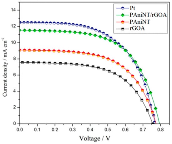
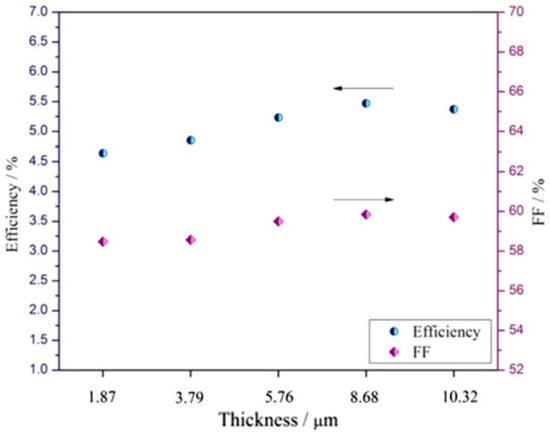
Figure 9. J-V characteristics of DSSCs fabricated with PAniNT, RGOA, PAniNT/rGOA, and Pt counter electrode (top figure) and photovoltaic parameters of DSSCs fabricated with PAniNT/rGOA CEs of different thicknesses under irradiation of 100 mW cm−2 light (bottom figure) [62].
Inside CPs/graphene or GD composites, the amount of the carbonaceous material within the composite determines the photoelectric performances. Thicker layers provide more catalytic sites and therefore enhance the rate of the reduction processes at the CE. Another parameter important to be followed is the filler factor (FF). When the FF value is higher than the value it has in conventional photovoltaic cells (50%), this parameter describes a successful limitation of the recombination processes at the CP/carbonaceous material interface. The chemical capacitance (Cµ) is used to estimate the electro-catalytic performance of the composite, evaluating its stability and durability. Cµ depends on the active surface area and the pseudo-capacitive charging effect of PEDOT [82][83]. High capacitance value is correlated with lower RCT, higher Jsc, and FF, respectively (see Table 3). Related to Cµ is the double layer capacitance (Cdl), used to indicate the catalytic activity and the porosity of the composite structure. In terms of capacitance, the diffusion of I3− and I−, and the rate of the reduction process, DSSCs with CEs made of composites based on PEDOT: PSS and RGO have very good PCE values, almost reaching the value reported for Pt.
There are only a few occasions when the RCT is not correlated with a high catalytic activity. One of these cases was reported for composites based on PANI and graphene where, although the RCT of PANI/Gr is higher compared to the Pt RCT, the PCE values are very close (3.589% for Gr/PANI and 3.976 for Pt) [66]. This could be due to the fact that the Nyquist plot model used for Pt is not appropriate to be used for carbonaceous compounds.
As a general observation based on the analysis of different combinations of graphene and CPs, Chawarambwa, F.L. and co-workers concluded that the addition of a carbonaceous compound reduces the internal resistance of the composite [58]. The reduction process that occurs at CE involve two steps:
I3− + 2 e− → 3 I− (1)
3 I2 + 2 e− → 2 I3− (2)
and the two potential peaks, positive and negative, correspond to the catalytic activity at the CE/I3−/I− interface and to the activity of the I2/I3− from the electrolyte/dye interface [84]. With these two parameters, positive and negative potential peaks the list of parameters describing the catalytic performance of CE inside DSSCs is extended.
The list of parameters used to describe the catalytic activity of CE continues with the charge density peaks (Jox and Jred) together with the peak separation (ΔEp) of the reduction and oxidation peak potentials from the redox couple (2I3−/I−). An excellent electro-catalytic behavior is revealed through a high value of current density (Jsc) and low peak separation. According to Dissanayake, M.A.K.L. and co-workers, for the RGO/PANI composite decorated with SnO2 nanoparticles a higher value of Jox (1.1 mA/cm2) was recorded, compared to RGO (0.53 mA/cm2) and RGO/SnO2 (0.98 mA/cm2 Jox), revealing an improved catalytic activity of the first, followed by a peak separation value for RGO/SnO2/PANI close to the one recorded for Pt (0.21 V). A lower ΔEp corresponds to higher electro-catalytic activity in the reduction process of the triiodide ion (I3−).
There are also inconveniences regarding the quality of composite components. For example, the incomplete reduction of RGO leads to low conductivity involving low charge transfer in the DSSCs [61] and another problem in determining the optimum amount of graphene compound used inside the composite, above the set limit, with the graphene layer overlap causing slow charge transport.
4. Synthesis and Vibrational Properties of CPs-CNs Composites as EM for Supercapacitors
4.1. Introduction in the Supercapacitors Cells
Recently, numerous studies have been reported on the use of CP-based composite materials, especially PANI and CNs of the type CNTs, graphene, and their derivatives or hybrids, resulted from the combination of the two, in a wide range of applications, in particular, as EMs in DSSCs [16][20][22][24][60][62][68][81] and supercapacitors [85][86][87][88][89][90][91][92][93][94][95][96][97][98][99][100][101]. In the composite configuration, the two components, i.e., CP and the carbon-based material, make their main contribution, the former through chemical stability, mechanical resistance, and redox behavior (PEDOT, PANI) and the latter through conductivity character and a high specific surface area. While in the previous chapter the discussion was mostly focused on DSSCs, this chapter highlights a brief description of the role of PANI/CNs composites as an EM in supercapacitors, where CNs are represented by CNTs and RGO. The description of the two types of electrode composite materials aims to obtain an overview of the aspects that control the synthesis of composites, significantly influencing the electrochemical capacitive performance of the material, the fundamental properties of these EMs being evaluated in terms of specific capacitance and charge/discharge rate.
The explanation for the fact that PANI is the most common CP used in supercapacitor EM lies in its excellent specific capacitance [102], plus the advantages of obtaining relatively simple and economical synthesis by chemical polymerization in an aqueous medium, as well as high stability in air [103]. Its main drawback, correctable by combining with CNs is poor conduction and low stability when used in repeated cycles. The latter is due to the significant changes taking place in the volume of the polymer matrix, being closely related to the processes of doping and de-doping [103]. The combination of PANI and CNs of the type CNTs or graphene or its derivatives is not accidental. Carbon-based materials exhibit very good capacitive behavior (often used as a current collector), high porosity that comes with a large specific surface area, and high chemical and mechanical stability. Thus, by introducing CNs into the polymer matrix, capacitance retention increases during repeated charge/discharge cycles, thus increasing cyclic stability and the charge/ion transfer rate between electrode and electrolyte, as well as the specific capacitance of the device, even at high current densities [104].
The capacitive behavior of the two components, CP and CNs, is different but contributes equally to the value of the final capacitance. PANI and other CPs with redox behavior exhibit pseudo-capacitive or Faradaic behavior where charge storage at the electrode surface occurs through the oxidation–reduction reactions that take place between the EM and the ions in the electrolyte, according to the mechanism reported by Jain D. et al. [86]:
CP → CPn+ + ne− (p doping); (3)
CP + ne− → CPn− (n doping).
In the case of PANI, since it can store charges both in the electric double layer (EDLC) and through the Faradaic charge mechanism, it has been successfully used as an EM for supercapacitors [105]. On the other hand, carbonaceous compounds exhibit both pseudo-capacitive and non-faradaic behavior specific to double-layer capacitors, so called because in non-Faradaic behavior charge storage occurs in the electric double layer at the electrode-electrolyte interface. For storage capacity evaluation, often are recorded (a) cyclic voltammograms at different potential scanning speeds; (b) charge/discharge galvanostatic curves, when a dependence of voltage as a function of time, and (c) for a more detailed study, the Nyquist diagram is made based on electrochemical impedance spectroscopy (EIS) measurements used for the study of charge transfer within the composite, where the main traced parameter is the charge transfer resistance constant which is calculated from the diameter of the semicircle in the Nyquist graph [106]. A low value of charge transfer resistance corresponds to a high value of specific capacitance [107]. Due to the different nature of the two or even three components, in the case of composites, Faradaic and non-Faradaic behaviors occur simultaneously, leading to a greater storage capacity.
For carbon-based compounds, such as graphene, pseudocapacitive behavior is evidenced by a rectangular profile of cyclic voltammograms. This type of behavior is also visible in PANI and other CPs with reversible redox behavior, such as polypyrrole [108][109]. Comparing the cyclic voltammograms profile of the individual components and the composite, a number of differences such as the pseudo-capacitive contribution of PANI is noticed [110][111], evidenced by the deviation from the symmetrical triangular shape visible in the case of the composite with CNs. Analysis of charge–discharge galvanostatic (CDG) curves helps to understand the behavior of EM. The profile of the voltage (E)–time (t) curves is triangularly symmetrical in the case of carbon-based materials with ideal capacitive behavior such as CNTs.
The most important parameters of a supercapacitor are the specific energy and power density, which are calculated according to the relationships:
E = 1/2M × Cd × V2 and (5)
P = 1/4M × (ESR) × V2,
Cd = I × ∆t ∆V,
Cs = I × ∆t ∆V × M = Cd M, for an electrode;
Cs = 2 × Cd M for an assembly analogous to a supercapacitor.
Electrochemical impedance measurements evaluate the transport ability of materials. By interpreting the Nyquist graph, important information about the bulk material resistance (Rb) and charge transfer resistance (RCT) is obtained. The graph is divided into three zones, the area of low, medium and high frequencies. In the first portion, in the area of low frequencies, the diagram has a step aspect and is an indicator of the capacitive nature of the material [113], while in the middle area, the profile of the graph is usually linear, and at high frequencies it is in the form of a semicircle. In the high-frequency region, the impedance spectrum depends on the load transport process, while in the low-frequency region mass transport processes dominate. For example, in the case of the PANI-Fe3O4/RGO composite [113], analyzing the spectra through EIS, it is observed that in the case of both RGO/Fe3O4 and the ternary composite, the charge transfer resistance is low in the high-frequency region and according to the appearance of the graph portion at low frequencies, namely the linear profile, with a slope of about 70°, indicating an ideal capacitive behavior of PANI nanorods [113]. PANI’s nanorod structure has recently been shown to significantly improve the capacitive performance of composites used as EMs in supercapacitors, where the energy storage capacity of a redox material is described by the equation: q t = q electrolyte + q dl + q electrode, where q t is the total charge stored in the electrode, q electrolyte is the charge stored due to the electrolyte, q dl represents the storage capacity of the double layer, and q electrode the charge stored in the active material of the redox electrode [87].
4.2. Synthesis and Vibrational Properties of PANI-RGO Composites as Well as Their Performance in Supercapacitors
A very clear application for highlighting the performance of a supercapacitor was made by S. Mondal and his collaborators, who, using the template method, synthesized a ternary composite EM based on PANI and RGO decorated with Fe3O4 nanoparticles. Mondal S. and colleagues made electrodes from this ternary composite for a supercapacitor that supported the operation of an LED bulb for 30 min [87]. The material synthesized by them had a very good stability, with a capacitance retention of 78% after 5000 cycles. Thus, the transition metal oxide, in the structure of the composite, contributes to increasing its stability and storage capacity. Among the transition metal oxides used in the manufacture of supercapacitors, Fe3O4 stands out by the large potential window in which it is active, between −1.2 and +0.25 V, benefiting from a theoretical Cs of 2299 F/g plus increased availability, being from natural sources, low cost, and low toxicity, which recommends it for use as an electrode material with pseudo-capacitive properties.
The presence of PANI and RGO in the nanocomposite structure results in the formation of a conductive network due to the π-π conjugation between PANI and RGO-Co3S4. This phenomenon reduces the electron path length and the diffusion length of the ions in the active material, thus increasing the inner active space, and the possibility of storing more charge weight.
PANI has been used with good results as an EM for supercapacitors, as it can store charges in the EDLC as well as through the Faradaic charge mechanism. In combination with graphene, results on capacitive efficiency of PANI/RGO composite EMs have been reported both in binary combination [88][89][90][91][114] and in ternary composites [87][92][93] and in combination with ionic liquids [94] whose pseudo-capacitive effect is already known [94][115]. Thus, Meriga, V. et al. reported the EM PANI chlorosulfonate/RGO composite with a specific capacitance of 120 F/g in 2015 [91], a value that gradually increased with the addition of transition metal oxide, Fe3O4, to 283.4 F/g at a current density of 1 A/g [114] and 797.5 F/g at 0.5 A/g with a very good capacitance retention of 92.43% of baseline, after 1000 cyclic voltammograms for the ternary composite with Co3S4, in which covalent functionalization of RGO-Co3S4 with PANI takes place [92]. The Cs of the RGO composite also increases when doping RGO with N takes place (282 F/g at 1 A/g) [90], an important aspect in obtaining superior capacitive performance being the porous 3D structure of the synthesized EM, which increases its interaction with the electrolyte facilitating ion transfer at the electrode/electrolyte interface. It has also been shown that the use of 3D structures made of PANI/RGO composite gel leads to greatly improved Cs values, as is the case of the study reported by Wang, Z. et al. [89] on the PANI/RGO composite when a Cs value was recorded of 423 F/g at 0.8 A/g, with a retention of 75% after 1000 cyclic voltammograms. The synthesis morphology of PANI and RGO is also a very important parameter that significantly influences the specific capacitance value of the tested EM; thus, the composite formed by PANI nanowires in combination with 3D type structure of the N-doped RGO leads to a Cs of 385 F/g at 0.5 A/g [116]. Of all of the capacitive values reported, the largest are still maintained on ternary composites with single or double oxides of transition metals, with an additional pseudo-capacitive effect, such as MnO2 [117], NiCo2O4 [93], and others (see Table 4), with a capacitance of 1090.2 F/g at 0.5 A/g and 1235 F/g at 60 A/g, respectively.
Table 4. PANI-RGO composites, synthesis methods, morphology, and capacitive performance.
| Composite | Morphology | Synthesis Method | Cs (F/g) | E (Wh/kg) |
P (KW/kg) |
Ref. |
|---|---|---|---|---|---|---|
| Ternary composite rGO/Fe3O4/PANI | 3D Nanorods of PANI doped with RGO decorated with Fe3O4 | Template method | 283.4 | 47.7 | 550 | [87] |
| RGO/PPy/Cu2O-Cu (OH)2 | Electrochemical polymerization | 997 la 10 A/g, | 20 | 8000 19,998.5 |
[118] | |
| PANI-RGO | Globular or nano rods PANI on the surface of the RGO | In situ oxidative polymerization Pe RGO |
797.5 F/g la 0.5 A/g, 92.43% after 1000 cycles | [92] | ||
| PANI-RGO | 3D Porous composite PANI/RGO, with a specific surface of 228 m2/g | Oxidative polymerization | 420 F/g la 0.2 A/g, 80% after 6000 cycles at 2 A/g | 9.3 for symmetric supercapacitor | 0.1 | [96] |
| PANI-RGO | RGO sheets randomly aggregated and closely linked together, uniformly coated by PANI nanofibers | Polymerization method surfactant-assisted |
444 F/G la 0.6 A/g | 13.36 W × h/kg | 1.03 kW/kg | [86] |
| 3D composite of the type RGO doped with N-PANI | PANI nanowires | In situ chemical polymerization | 282 F/g la 1 A/g, 64.5% after 1000 cycles | - | - | [90] |
| PANI-RGO | Planar sheets of RGO, granular matrix of chlorosulfonated PANI | Chemical oxidation | 120 F/g for PANI-RGO, 94% RGO | - | - | [91] |
| PANI/RGO | 3D structure printing | 1329 mF/cm2 423 F/g at 0.8 A/g |
- | - | [89] | |
| PANI- tannic acid -RGO | Micro-fibrillary network of PANI | In situ oxidative chemical polymerization | 268.5 F/g t 10 mV/s | 1.68 la 0.5 A/g in symmetric supercapacitors | 115 | [88] |
| PANI-RGO- carbon fiber, ternary composite | Aggregate sheets with fine layers of PANI | Electrochemical method | 430 F/g at 10−3 Hz | - | - | [95] |
| RGO/CNT-PANI | Fiber-shaped electrodes, skeleton/skin structure | GO reduction, PANI electrodeposition | 193.1 F/cm3 at 1 A/cm3, 80.6% after 2000 cycles | 0.98 (mW × H/cm3) | 16.25 (mW/cm3) | [97] |
| NiCo2O4/PANI/rGO | Granular shape of PANI emeraldine base | Chemical polymerization | 1235 F/g t 60 A/g, 78% after 3500 cycles | 45.6 W × h/kg | 610.1 kW/kg | [93] |
| PANI-RGO | Composite gel with 3D structure, porous | Self-assembly followed by a reduction process | 808 F/g at 53.33 A/g | - | - | [98] |
| RGO-PANI | Nano-rods | Chemical polymerization | 524.4 F/g at 0.5 A/g, 81.1% after 2000 cycles at 100 mV/s | - | - | [99] |
| PANI-RGO | Fibrillary morphology | In situ chemical polymerization | 250 F/g | - | - | [100] |
| RGO-ion liquid/PANI (RGO-IL/PANI) | Excellent flexibility | In situ chemical polymerization | RGO-IL: 193 F/g at 1 A/g with 87% after 2000 cycles at 5 A/g | 24.1 | 501 | [94] |
| RGO-PANI | Dendritic nanofibers of PANI | Chemical polymerization | 1337 F/g at 15 A/g, 81.25% after 5000 cycles | - | - | [114] |
| PANI-RGO- nanocellulose | Fibers | Chemical synthesis | 79.71 F/g | Power density from 110.45 to 50.65 W/kg | - | [101] |
In the case of composites based on CPs and CNs, as is the case with PANI/RGO/carbon fibers (CFs), some changes associated with the pseudo-capacitive contribution of PANI show the E-t-profile. Thus, the E-t profile of the composite deposited on CF has two areas: the first area corresponds to a shoulder due to faradaic processes (PANI) and the second area is linear, representing the capacitive process [95].
In the case of the covalent functionalization of RGO with PANI, the reported specific capacitance was 797.5 F/g at 0.5 A/g at a retention of 92.43% after 1000 cycles [92].
A three-dimensional structure of N-doped and PANI-coated RGO has also been reported by Liu, Z. et al. [90] resulting from the in situ chemical polymerization synthesis of PANI in the presence of N-doped RGO using β-MnO2 oxidant and polystyrene sacrificial microspheres to create the 3D structure of the RGO network.
Another type of morphology, namely well-separated planar sheets of RGO, without aggregation or association, embedded in the granular matrix of chlorosulfonated PANI, was reported by Meriga, V. and co-workers [91]; this composite material was synthesized by the chemical oxidation polymerization method of ANI in the presence of APS. EMs can also be printed as 3D structures using PANI/GO gel, obtained by the self-assembly method of PANI and GO in a mixture of NMP and water [89], with a capacitance of 423 F/g at 0.8 A/g for the PANI-RGO composite. In order to decrease the toxic compounds used in the reduction process of GO to RGO, Zhao, X. et al. tested tannic acid, a non-toxic compound successfully used for GO to RGO conversion, which influenced the morphology of the obtained composite, namely the PANI microfibrillar network [88]. After 24 h of reaction with tannic acid, the resulting RGO shows a higher specific surface area, a better distribution of PANI fibers on the surface, and a higher specific capacitance compared to the hydrazine-reduced PANI and RGO-based composite. The composite presented above recorded an energy density of 1.68 at 0.5 A/g, and respectively, a power density of 115 KW/kg in the symmetric supercapacitor.
A high capacitance (808 F/g at 53.33 A/g) [98] has been reported for binary PANI/RGO composites, synthesized by two successive processes of self-assembly in a mixture of water and NMP followed by the three-dimensional reduction of the assembly. The highest capacitance value of the PANI-RGO binary composite was reported by Nguyen, Van H. and co-workers (1337 F/g at 15 A/g) [114]. The composite material was prepared using a two-step synthesis method, this being in the form of thin distinct GO sheets with differentiated, wafer-like edges, coated with dendritic PANI nanofibers of 100 nm diameter and micron length. The very low size morphology of PANI is attributed to the chain structure of PANI molecules formed on the surface of RGO sheets [114]. On the other hand, ternary PANI-RGO-oxide composites have been synthesized by a number of methods that significantly influence the morphology of the resulting material. Thus, 3D nano rod-like structures of RGO-doped PANI decorated with Fe3O4 particles have been obtained by in situ polymerization [87]; 3D structures of the type RGO/PPy/Cu2O-Cu (OH)2 with very high power densities 8000 KW/kg were obtained by in situ electrochemical polymerization of RGO/PPY on Nickel foam followed by Cu2O-Cu (OH)2 deposition by chronoamperometry [118]. The granular morphology of PANI-EB in the NiCo2O4/PANI/rGO composite was reported by Rashti, A. et al., the NiCo2O4 particles were distributed on the PANI functionalized RGO lattice [93]. The ternary composite was tested in a three-electrode configuration, showing a capacitance value of 1235 F/g at 60 A/g, and in the solid-state asymmetric supercapacitor, the composite acted as cathode and the activated carbon acted as anode, the cell showing a specific capacitance of 262.5 F/g at 1 A/g, with a retention of 78% after 3500 cycles at a working potential of +1.5 V.
Charge storage properties of the composites were tested by GCD. In the case of ternary composite made of RGO, Fe3O4, and PANI [87] the electrochemical study together with the charge–discharge curves, recorded at 1 A/g, revealed the capacitance behavior of all stages of the composite from binary to ternary, namely for GO, RGO/Fe3O4 (RGF), and RGO/Fe3O4/PANI. Therefore, the quasi-triangular shape of the GCD spectrum corresponding to RGO/Fe3O4 and RGO/Fe3O4/PANI compared to the ideal triangular GO spectrum shape indicates the presence of two types of capacitances, namely the double-layer capacitance associated with GO and the pseudocapacitance of both PANI and Fe3O4. The longer charge–discharge time is directly related to an improved charge storage mechanism.
Electrochemical impedance spectroscopic (EIS) studies of GO, rGF, and rGFP composite have been measured in the range 0.1 to 100 kHz. They were performed to evaluate the transport processes within the composites. The impedance spectrum with the two main regions, namely the high-frequency region and low-frequency region is governed by the charge transport process, respectively, by the mass transport process. In the case of RGO/Fe3O4 and RGO/Fe3O4/PANI in the higher frequency region (Figure 10c), the semicircle is negligible, revealing the significantly low interfacial charge transfer resistance. In this region, both resistance (8.3 Ω) and charge transfer are low (2.03 Ω).
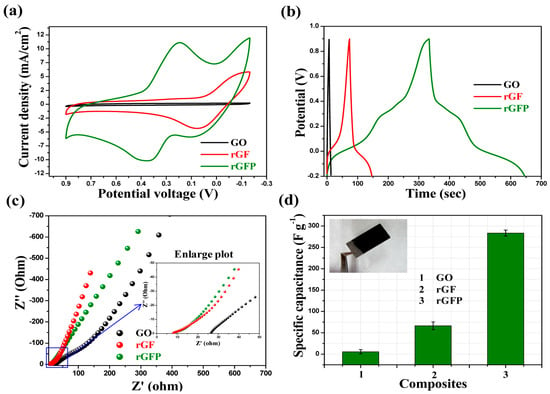
Figure 10. Electrochemical measurement (using the three-electrode system) of synthesized composites: (a) CV study (scan rate of 50 mV/s), (b) GCD study (at 1 A/g current density), (c) EIS study (Nyquist plot, in the 0.1–100,000 Hz range), and (d) a bar plot for specific capacitance. All measurements were made in a 0.5 M H3PO4 aqueous solution [87].
The slope of the vertical line, at the low-frequency region, is around ~70° indicating the nearly ideal capacitive behavior of the nanorods composite. The specific capacitance (Cs) value for synthesized rGFP ternary composites is high (283.4 F/g) compared to GO (5.5 F/g), respectively, to the binary RGF (66.4 F/g) (Figure 10).
When the EM was represented by RGO-ionic liquid/PANI (RGO-IL/PANI) [94], the reported capacitance was 193 F/g at 1 A/g due to RGO modification with ionic liquid, and a retention capacity of 87% after 2000 cycles at 5 A/g.
Composite materials based on CNTs and CPs, in particular PANI, with applications in the field of supercapacitors have also been reported. These composites generally obtained by oxidative polymerization of ANI in the presence of CNTs [119], respectively, by electrochemical polymerization of ANI on CNTs [120], exhibit three-dimensional structures with superior mechanical and electrical properties, a porous structure, and the ion diffusion property [104] (see Table 5). According to the study conducted by Malik, R. [104], a combination of vertically aligned N-doped CNTs in the form of the CNTs sheets were uniformly coated with a PANI layer, the final material having a core-shell morphology. Thus, the values of Cs reported were 359 F/g and 128 F/g at current densities of 4.95 A/g and 2.42 A/g, respectively, within the solid symmetric supercapacitor with PVA/H2SO4 type gel electrolyte composite layers between [104]. Vertically aligned N-doped CNTs have three times the specific surface area compared to classical N-doped CNTs and a pore size between 5 and 10 nm which favors PANI deposition and the rapid diffusion of electrolyte ions. According to Haq and co-workers [121], the N-doped centers in CNTs are the ANI polymerization initiation centers. Vertically aligned CNTs were grown on Ni-coated N-doped CNTs sheets by the CVD method from acetylene in an NH3 plasma atmosphere [104]. While N-doped CNT substrate sheets (NCNTs) behave as a current collector, vertically aligned CNTs grown on NCNT sheets mediate and accelerate electron transfer from PANI to NCNT layers. The structure retains the core-shell morphology even after 30 cyclic voltammograms and the capacitance retention is 80% after 5000 cyclic voltammograms plus the open porous diode structure which allows ion diffusion while maintaining high ionic conductivity [122][123][124]. Upon covalent interaction between PANI and CNTs, the composite obtained by depositing porous PANI over CNTs with an interconnected pore structure exhibits a Cs of 1266 F/g at 1 A/g, i.e., a retention of 83% after 10,000 cyclic voltammograms [107]. The porous morphology results in more efficient ion transport, faster charge transport due to electron delocalization, and better PANI stability in redox processes. PANI grafting to CNTs leads to the extension of PANI conjugation and thus to increased conductivity up to 3009 S/cm [125]. Charge accumulation and Faradaic redox-reducing properties are improved due to the pore structure and specific surface of the activated MWCNT and PANI-based EM (A-MWCNTs/PANI). Activation of MWCNTs is performed by treatment with HNO3 for better dispersion of MWCNTs in the polymer matrix. The Cs value is significantly improved from 42 F/g for A-MWCNTs to 201 F/g after introducing PANI into the EM. This is reflected in the higher current density increase in activated MWCNTs compared to the original ones, the activation positively influencing their porosity. The cyclic voltammograms show an almost rectangular and symmetrical profile, especially at low scan rates, indicating the high capacitive performance of the electrode–electrolyte system.
A frequently encountered problem in the behavior of EMs is maintaining a constant value of Cs at different values of current density. One material that meets this requirement is that reported by Ramana. G.V. and co-workers [119], namely the PANI/CNT composite obtained by oxidative chemical polymerization of ANI, with core-shell morphology and a Cs of 368.4 F/g. According to this study, the functionalization of CNTs prior to composite synthesis allows control of the oxidation state of PANI and can significantly improve the capacitive performance of the material. Another group of researchers, led by Zhou, H. [126], attempted to increase the capacitive performance of a PANI-CNT composite by using electrochemically expanded graphite (ExGP) as a current collector. By reducing the resistance at the EM/current collector interface they demonstrated increased electrochemical capacitance. The EM/current collector couple, mentioned above, has a capacitance of 826.7 F/g, much higher compared to other PANI/CNTs electrodes. The device made from the superposition of two PANI/CNT/ExGP type electrodes with a PVA/H2SO4 electrolyte layer interleaved is a flexible, solid-state supercapacitor with a power of 7.1 kW/kg at an energy density of 12 Wh/kg with a good cycle stability.
The CNTs used in the composite synthesis were functionalized with -COOH groups by exposure to concentrated acidic medium (H2SO4:HNO3 = 3:1 in volume percent). Due to the expanded graphite substrate, the PANI/CNT morphology is different, thus CNTs are evenly distributed along the PANI fibers, the close contact between the two suggesting the dual role of CNT, as a binding agent and conductive additive, which shortens the distance between the relatively dispersed PANI fibers, facilitating electrical contact between them. The overall appearance is of a core-shell structure, and the length of the CNTs is longer due to the coating with the polymer layer—which increases the specific surface area and thus the number of active centers available in pseudo-capacitive reactions. The formation of the core-shell structure occurs due to the electrostatic interaction between the negatively charged functionalized nanotubes (CNT-COO−) and the positive charges along the polymer chain of PANI. The higher specific capacitance of PANI/CNTs/ExGPs compared to PANI/ExGPs is evidenced by a larger cyclic voltammograms area and more intense redox maxima, respectively (Figure 11).
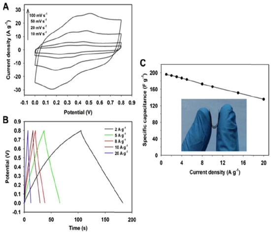
Figure 11. (A) Cyclic voltammograms profiles at the scan rates ranging from 10 to 100 mV s−1, (B) GCD curves at the current densities from 2 to 20 A g−1, and (C) plot of specific capacitance vs. GCD current density for the symmetric PANI-CNT/ExGP-based supercapacitor. The inset in (C) is an image showing the mechanical deformation of the PANI-CNT/ExGP-based supercapacitor [126].
Figure 12 shows the FTIR spectra of CNT, carboxylated CNT, PANI, and PANI-CNT. The FTIR spectrum of CNTs-COOH compared to CNT exhibits an additional peak (1715 cm−1), due to C=O stretching vibration in carboxyl groups [127], which is a proof that carboxyl groups were introduced into CNT during the functionalization process. The -COO− groups on the surface of CNTs neutralize the positive charges in the oxidized PANI chain, during electrochemically oxidative polymerization, thereby forming the CNT@PANI core-shell structure mentioned above. The PANI-CNT spectrum is almost similar with PANI spectrum the only difference being that the typical C=C bonds in PANI located at 1565 and 1487 cm−1 are red-shifted to 1555 and 1477 cm−1 in the FTIR spectrum of the composite, due to the interaction between CNT and p-electrons of PANI chains [128].
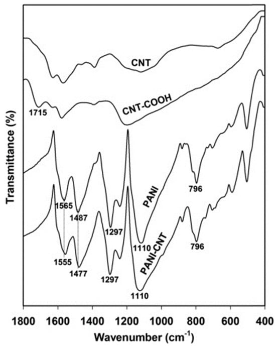
Figure 12. FT-IR spectra of CNT, CNT-COOH, PANI, and PANI-CNT.
CNTs could be prepared before interaction with PANI by the ball-milling process and subsequent exposure to acid solution. The resultant composite, MWCNT-PANI, exhibited a capacitance of 837.6 F/g at 1 mV/s [129]. The increase in anodic and cathodic current densities with increasing scan rate indicates a good material operating rate, which is accompanied by the large cyclic voltammograms area relative to that of the CNT indicating a large pseudo-capacitance of the electrode. Due to the electrostatic interactions of the positive charges in the PANI chain and the anions in the solution, floccules are formed that allow the ions to access their surface, reducing the distance between them and the PANI, favoring the charge/discharge processes. A special type of PANI/CNT composites are those in which the CNTs are open at one end (so-called partially unzipped CNTs), and play a role in favoring the access of ions from the electrolyte to the EM during charge–discharge processes, contributing decisively to increasing the mechanical strength of the EM. CNTs can be opened by several methods, such as chemical interaction with acids [130], intercalation and exfoliation of lithium ions [131], catalytic processes [132], electrical [133], and physical–chemical methods [134]. The CNT unbonding process consists of the longitudinal splitting of the nanotube, a procedure that results in one or more layers of graphene or a combination of inner tube and graphene nanosheets, depending on the number of CNT walls. While the first mentioned methods used to unzip the CNTs involve the use of chemical compounds, the last two are cleaner methods to shape the final product, namely graphene nanoribbons (GNR). While the electric method as it says uses the electrical current to tailor a graphene sheet in high vacuum conditions, the physical–chemical method assumes the coverage of CNTs casted on substrate (Silicon wafer) with a thick film of poly methyl methacrylate (PMMA), followed by heat treatment to strengthen the CNTs-PMMA structure. After that, it follows the exfoliation of the resulted CNTs-PMMA film from the substrate using the KOH solution. The final step represents the etching process which occurs by exposing the sample to 10 W Argon plasma, for various periods of time, resulting in one or multi-layered GNRs or a combination between GNR and CNTs depending of the CNTs number of walls.
Table 5. PANI-CNT composites, synthesis methods, morphology, and capacitive performance.
| Composite | Morphology | Synthesis Method | Cs (F/g) | Ref |
|---|---|---|---|---|
| PANI/CNTs | Homogeneously co-dispersed open tubes together with graphene nanostructures resulting from the process of opening tubes coated with a uniform polymer layer * | In situ oxidative polymerization | 762 with 81% retention after 1000 cyclic voltammograms | [85] |
| A-MWCNTs/PANI | Thick bundles of CNTs | In situ polymerization | 248 at 0.25 A/g, and 99.2 F/g at 5 A/g | [103] |
| PANI/NCNT (CNT dopat cu N) | Vertically aligned nanotubes grown perpendicular to horizontally aligned CNTs coated with a uniform layer of polymer, observed by increasing the diameter of the CNTs | Electrochemical deposition | 359 at 4.95 A/g with 82% retention at 46.87 mA/cm2 | [104] |
| Porous PANI/CNTs | Compact morphology | Chemical grafting by Ani interaction with -NH2-functionalized CNTs | 1266 F/g at 1 A/g, 83% after 10000 cyclic voltammograms | [107] |
| CNT-PANI | Shell-core structure | Oxidative chemical polymerization | 368.4 F/g at various current densities | [119] |
| Composite expanded graphite (ExGP)/PANI-CNT | Interconnected fiber microstructures interleaved with CNTs | Electrochemical co-deposition | 826.7 F/g | [127] |
| PANI/CNT | Polymer deposition on the surface of CNTs | In situ chemical polymerization | 837.6 F/g at 1 mV/s, 68% after 3000 cyclic voltammograms | [129] |
| PANI/MWCNTs | Nanofibrous structure | In situ chemical polymerization | 554 F/g at 1 A/g | [135] |
* Outer tube of partially destroyed MWCNTs transformed into graphene nano-ribbons and core-like inner tube in the PANI composite; a decreased diameter of PANI fibers was observed suggesting the coating of hybrid MWCNTs with a uniform polymer layer.
References
- Goldemberg, J.; Johansson, T.B. (Eds.) World Energy Assessment Overview: 2004 Update; Prepared for United Nations Development Programme, United Nations Department of Economic and Social Affairs, and the World Energy Council; United Nations Development Programme: New York, NY, USA, 2004; p. 88.
- Gao, J.; Yang, Y.; Zhang, Z.; Yan, J.; Lin, Z.; Guo, X. Bifacial quasi-solid-state dye-sensitized solar cells with Poly (vinyl pyrrolidone)/polyaniline transparent counter electrode. Nano Energy 2016, 26, 123–130.
- Li, Z.-Q.; Chen, W.-C.; Guo, F.-L.; Mo, L.E.; Hu, L.-H.; Hu, L.-H.; Dai, S.-Y. Mesoporous TiO2 Yolk-Shell Microspheres for Dye-sensitized Solar Cells with a High Efficiency Exceeding 11%. Sci. Rep. 2015, 5, 14178.
- O’Regan, B.; Grätzel, M. A low-cost, high-efficiency solar cell based on dye-sensitized colloidal TiO2 films. Nature 1991, 353, 737–740.
- Zhang, S.; Yang, X.; Numata, Y.; Han, L. Highly efficient dye-sensitized solar cells: Progress and future challenges. Energy Environ. Sci. 2013, 6, 1443–1464.
- Mishra, A.; Fischer, M.K.R.; Bauerle, P. Metal-free organic dyes for dye-sensitized solar cells: From structure: Property relationships to design rules. Angew. Chem. Int. Ed. 2009, 48, 2474–2499.
- Liang, M.; Chen, J. Arylamine organic dyes for dye-sensitized solar cells. Chem. Soc. Rev. 2013, 42, 3453–3488.
- Boschloo, G.; Hagfeldt, A. Characteristics of the iodide/triiodide redox mediator in dye-sensitized solar cells. Acc. Chem. Res. 2009, 42, 1819–1826.
- Susmitha, K.; Kumari, M.M.; Berkmans, A.J.; Kumar, M.N.; Giribabu, L.; Manorama, S.V.; Raghavender, M. Carbon nanohorns based counter electrodes developed by spray method for dye sensitized solar cells. Sol. Energy 2016, 133, 524–532.
- Iijima, S. Helical microtubules of graphitic carbon. Nature 1991, 354, 56–58.
- Wang, G.; Xing, W.; Zhuo, S. Nitrogen-doped graphene as low-cost counter electrode for high-efficiency dye-sensitized solar cells. Electrochim. Acta 2013, 92, 269–275.
- Yue, G.; Wu, J.; Xiao, Y.; Huang, M.; Lin, J.; Fan, L.; Lan, Z. Platinum/graphene hybrid film as a counter electrode for dye-sensitized solar cells. Electrochim. Acta 2013, 92, 64–70.
- Peng, Y.; Zhong, J.; Wang, K.; Xue, B.; Cheng, Y.-B. A printable graphene enhanced composite counter electrode for flexible dye-sensitized solar cells. Nano Energy 2013, 2, 235–240.
- Tai, Q.; Chen, B.; Guo, F.; Xu, S.; Hu, H.; Sebo, B.; Zhao, X.-Z. In situ prepared transparent polyaniline electrode and its application in bifacial dye-sensitized solar cells. ACS Nano 2011, 5, 3795–3799.
- Suzuki, K.; Yamaguchi, M.; Kumagai, M.; Yanagida, S. Application of carbon nanotubes to counter electrodes of dye-sensitized solar cells. Chem. Lett. 2003, 32, 28–29.
- Liu, X.; Liang, Y.; Yue, G.; Tu, Y.; Zheng, H. A dual function of high efficiency quasi-solid-state flexible dye-sensitized solar cell based on conductive polymer integrated into poly (acrylic acid-co-carbon nanotubes) gel electrolyte. Sol. Energy 2017, 148, 63–69.
- Kulicek, J.; Gemeiner, P.; Omastová, M.; Mičušík, M. Preparation of polypyrrole/multi-walled carbon nanotube hybrids by electropolymerization combined with a coating method for counter electrodes in dye-sensitized solar cells. Chem. Pap. 2018, 72, 1651–1667.
- Yun, D.J.; JinJeong, Y.; Ra, H.; Tae, J.-M.; An, K.; Rhee, S.-W.; Jang, J. Systematic optimization of MWCNT-PEDOT:PSS composite electrodes for organic transistors and dye-sensitized solar cells: Effects of MWCNT diameter and purity. Org. Electron. 2018, 52, 7–16.
- Lee, J.H.; Jang, Y.J.; Kim, D.W.; Cheruku, R.; Thogiti, S.; Ahn, K.-S.; Kim, J.H. Application of polypyrrole/sodium dodecyl sulfate/carbon nanotube counter electrode for solid-state dye-sensitized solar cells and dye-sensitized solar cells. Chem. Pap. 2019, 73, 2749–2755.
- Bumika, M.; Mallick, M.K.; Mohanty, S.; Nayak, S.K.; Palai, A.K. One-pot electrodeposition of polyaniline/SWCNT/ZnO film and its positive influence on photovoltaic performance as counter electrode material. Mat. Lett. 2020, 279, 128473.
- Rafique, S.; Rashid, I.; Sharif, R. Cost effective dye sensitized solar cell based on novel Cu polypyrrole multiwall carbon nanotubes nanocomposites counter electrode. Sci. Rep. 2021, 11, 14830.
- AbdulAlmohsin, S.M.; Khedhair, A.A.; Ajeel, S.K. Facile synthesis of polyaniline-single wall carbon nanotube nanocomposite as hole transport material and zinc oxide nanorodes as metal oxide to integration solid-state dye-sensitized solar cells. Univ. Thi-Qar J. 2019, 14, 1–13.
- Dawo, C.; Iyer, P.K.; Chaturvedi, H. Carbon nanotubes/PANI composite as an efficient counter electrode material for dye sensitized solar cell. Mater. Sci. Eng. B 2023, 297, 116722.
- Li, H.; Xiao, Y.; Han, G.; Li, M. Honeycomb-like polypyrrole/multi-wall carbon nanotube films as an effective counter electrode in bifacial dye-sensitized solar cells. J. Mater. Sci. 2017, 52, 8421–8431.
- Li, H.; Xiao, Y.; Han, G.; Hou, W. Honeycomb-like poly(3,4-ethylenedioxythiophene) as an effective and transparent counter electrode in bifacial dye-sensitized solar cells. J. Power Sources 2017, 342, 709–716.
- Li, Q.H.; Tang, Q.W.; Lin, L.; Chen, X.X.; Chen, H.Y.; Chu, L.; Xu, H.T.; Li, M.J.; Qin, Y.C.; He, B.L. A simple approach of enhancing photovoltaic performances of quasi-solid-state dye-sensitized solar cells by integrating conducting polyaniline into electrical insulating gel electrolyte. J. Power Sources 2014, 245, 468–474.
- Li, Q.H.; Chen, X.X.; Tang, Q.W.; Cai, H.Y.; Qin, Y.C.; He, B.L.; Li, M.J.; Jin, S.Y.; Liu, Z.C. Enhanced photovoltaic performances of quasi-solid-state dye sensitized solar cells using a novel conducting gel electrolyte. J. Power Sources 2014, 248, 923–930.
- Guo, H.F.; Zhu, H.; Lin, H.Y.; Zhang, J. Polypyrrole–multi-walled carbon nanotube nanocomposites synthesized in oil–water microemulsion. Colloid Polym. Sci. 2008, 286, 587–591.
- Ham, H.; Choi, Y.; Jeong, N.; Chung, I. Single wall carbon nanotubes covered with polypyrrole nanoparticles by the miniemulsion polymerization. Polymer 2005, 46, 6308–6315.
- Tang, Z.; Wu, J.; Li, Q.; Lan, Z.; Fan, L.; Lin, J.; Huang, M. The preparation of poly (glycidyl acrylate)–polypyrrole gel-electrolyte and its application in dye sensitized solar cells. Electrochim. Acta 2010, 55, 4883–4888.
- Mudiyanselage, T.; Neckers, D. Photochromic superabsorbent polymers. Soft Matter 2008, 4, 768–774.
- Zerbi, G.; Gussoni, M.; Castiglioni, C. Vibrational spectroscopy of polyconjugated aromatic materials with electrical and nonlinear optical properties. In Conjugated Polymers; Springer Netherlands: Dordrecht, The Netherlands, 1991; Volume 259, pp. 435–507.
- Peng, S.; Wu, Y.; Zhu, P.; Thavasi, V.; Mhaisalkar, S.G.; Ramakrishna, S. Facile fabrication of polypyrrole/functionalized multiwalled carbon nanotubes composite as counter electrodes in low-cost dye-sensitized solar cells. J. Photochem. Photobiol. A Chem. 2011, 223, 97–102.
- Chakraborty, G.; Gupta, K.; Meikap, A.K.; Babu, R.; Blau, W.J. Synthesis, electrical and magnetotransport properties of polypyrrole-MWCNT nanocomposite. Solid State Commun. 2012, 152, 13–18.
- Ghani, S.; Sharif, R.; Bashir, S.; Zaidi, A.A.; Rafique, M.S.; Ashraf, A.; Shahzadi, S.; Shaista, R.; Kamboh, A.H. Polypyrrole thin flms decorated with copper nanostructures as counter electrode for dye-sensitized solar cells. J. Power Sources 2015, 282, 416–420.
- He, B.; Tang, Q.; Luo, J.; Li, Q.; Chen, X.; Cai, H. Rapid charge transfer I polypyrrole single wall carbon nanotube complex counter electrodes: Improved photovoltaic performances of dye-sensitized solar cells. J. Power Sources 2014, 256, 170–177.
- Hlura, H.; Ebbesen, T.W.; Tanigaki, T.; Takahashi, H. Raman studies of carbon nanotubes. Chem. Phys. Lett. 1993, 202, 509–512.
- de Heer, W.A.; Bacsa, W.S.; Chatelain, A.; Gerfin, T.; Humphrey-Baker, R.; Forro, L.; Ugarte, D. Aligned carbon nanotube films: Production and optical and electronic properties. Science 1995, 268, 845–847.
- Liu, J.S.; Tanaka, T.; Sivula, K.; Alivisatos, A.P.; Fréchet, J.M.J. Employing End-Functional Polythiophene to Control the Morphology of Nanocrystal−Polymer Composites in Hybrid Solar Cells. J. Am. Chem. Soc. 2004, 126, 6550–6551.
- Liu, Y.-C.; Hwang, B.-J.; Jian, W.-J.; Santhanam, R. In situ cyclic voltammetry-surface-enhanced Raman spectroscopy: Studies on the doping–undoping of polypyrrole film. Thin Solid Film. 2000, 374, 85–91.
- Zhang, D.W.; Li, X.D.; Chen, S.; Tao, F.; Sun, Z.; Yin., X.J.; Huang, S.M. Fabrication of double-walled carbon nanotube counter electrodes for dye-sensitized solar cells. J. Solid State Electrochem. 2010, 14, 1541–1546.
- Siuzdak, K.; Klein, M.; Sawczak, M.; Wroblewski, G.; Sloma, M.; Jakubowska, M.; Cenian, A. Spray-deposited carbon-nanotube counter electrodes for dye-sensitized solar cells. Phys. Status Solidi A 2016, 213, 1157–1164.
- Tison, Y.; Giusca, C.E.; Stolojan, V.; Hayashi, Y.; Silva, S.R.P. The inner shell influence on the electronic structure of double-walled carbon nanotubes. Adv. Mater. 2008, 20, 189–194.
- Yang, S.; Huo, J.; Song, H.; Chen, X. A comparative study of electrochemical properties of two kinds of carbon nanotubes as anode materials for lithium ion batteries. Electrochim. Acta 2008, 53, 2238–2244.
- Li, W.Z.; Wen, J.G.; Sennett, M.; Ren, Z.F. Clean double-walled carbon nanotubes synthesized by CVD. Chem. Phys. Lett. 2003, 368, 299–306.
- Belin, T.; Epron, F. Characterization methods of carbon nanotubes: A review. Mat. Sci. Eng. B 2005, 119, 105–118.
- Peigney, A.; Laurent, C.; Flahaut, E.; Bacsa, R.R.; Rousset, A. Specific surface area of carbon nanotubes and bundles of carbon nanotubes. Carbon 2001, 39, 507–514.
- Fan, B.; Mei, X.; Sun, K.; Ouyang, J. Conducting polymer/carbon nanotube composite as counter electrode of dye sensitized solar cells. Appl. Phys. Lett. 2008, 93, 143103.
- Duchet, J.; Legras, R. Demoustier-Champagne, S. Chemical synthesis of polypyrrole: Structure–properties relationship. Synth. Met. 1998, 98, 113–122.
- Gonçalves, A.B.; Mangrich, A.S.; Zarbin, A.J.G. Polymerization of pyrrole between the layers of α-Tin (IV) Bis (hydrogenphosphate). Synth. Met. 2000, 114, 119–124.
- Xiao, Y.M.; Wu, J.H.; Lin, J.Y.; Yue, G.T.; Lin, J.M.; Huang, M.L.; Lan, Z.; Fan, L.Q. A dual function of high performance counter-electrode for stable quasi-solidstate dye-sensitized solar cells. J. Power Sources 2013, 241, 373–378.
- Yue, G.T.; Wu, J.H.; Xiao, Y.M.; Lin, J.M.; Huang, M.L.; Lan, Z. Application of poly (3,4-ethylenedioxythiophene): Polystyrenesulfonate/polypyrrole counter electrode for dye-sensitized solar cells. J. Phys. Chem. C 2012, 116, 18057–18063.
- Hou, W.; Xiao, Y.; Han, G.; Zhou, H. Electro-polymerization of polypyrrole/multi wall carbon nanotube counter electrodes for use in platinum-free dye-sensitized solar cells. J. Mater. Sci. 2017, 190, 720–728.
- Li, H.; Xiao, Y.; Han, G.; Zhang, Y. A transparent honeycomb-like poly(3,4-ethylenedioxythiophene)/multi-wall carbon nanotube counter electrode for bifacial dye sensitized solar cells. Org. Electron. 2017, 50, 161–169.
- Aitola, K.; Borghei, M.; Kaskela, A.; Kemppainen, E.; Nasibulin, A.G.; Kauppinen, E.I.; Lund, P.D.; Ruiz, V.; Halme, J. Flexible metal-free counter electrode for dye solar cells based on conductive polymer and carbon nanotubes. J. Electroanal. Chem. 2012, 683, 70–74.
- Hernández-Ferrer, J.; Ansón-Casaos, A.; Martínez, M.T. Electrochemical synthesis and characterization of single-walled carbon nanotubes/polypyrrole films on transparent substrates. Electrochim. Acta 2012, 64, 1–9.
- Lee, K.S.; Lee, Y.; Lee, J.Y.; Ahn, J.-H.; Park, J.H. Flexible and Platinum-Free dye-sensitized solar cells with conducting-polymer-coated graphene counter electrodes. ChemSusChem 2012, 5, 379–382.
- Chawarambwa, F.L.; Putri, T.E.; Son, M.-K.; Kamataki, K.; Itagaki, N.; Koga, K.; Shiratani, M. Graphene-S3N4 nanocomposite blended polymer counter electrode for low-cost dye-sensitized solar cells. Chem. Phys. Lett. 2020, 758, 137920.
- Sudhakar, V.; Singh, A.K.; Chini, M.K. Nanoporous reduced graphene oxide and polymer composites as efficient counter electrodes in dye-sensitized solar cells. ACS Appl. Electron. Mater. 2020, 2, 626–634.
- Mehmood, U.; Karim, N.A.; Zahid, H.F.; Asif, T.; Younas, M. Polyaniline/graphene nanocomposites as counter electrode materials for platinum free dye-sensitized solar cells (DSSCSs). Mater. Lett. 2019, 256, 126651.
- Loryuenyong, V.; Khadthiphong, A.; Phinkratok, J.; Watwittayakul, J.; Supawattanakul, W.; Buasri, A. The fabrication of graphene-polypyrrole composite for application with dye-sensitized solar cells. Mater. Today Proc. 2019, 17, 1675–1681.
- Mohan, K.; Bora, A.; Roy, R.S.; Nath, B.C.; Dolui, S.K. Polyaniline nanotube/reduced graphene oxide aerogel as efficient counter electrode for quasi-solid state dye sensitized solar cell. Sol. Energy 2019, 186, 360–369.
- Saranya, K.; Rameez, M.; Subramania, A. Developments in conducting polymer based counter electrodes for dye-sensitized solar cells–an overview. Eur. Polym. J. 2015, 66, 207–227.
- Gunasekera, S.S.B.; Perera, I.R.; Gunathilaka, S.S. Conducting Polymers as Cost Effective Counter Electrode Material in Dye-Sensitized Solar Cells. In Solar Energy; Springer: Berlin/Heidelberg, Germany, 2020; pp. 345–371.
- Hou, W.; Xiao, Y.; Han, G.; Lin, J.-Y. The applications of polymers in solar cells: A review. Polymers 2019, 11, 143.
- Shahid, M.U.; Mohamed, N.M.; Muhsan, A.S.; Bashiri, R.; Shamsudin, A.E.; Zaine, S.N.A. Few-layer graphene supported polyaniline (PANI) film as a transparent counter electrode for dye-sensitized solar cells. Diam. Relat. Mater. 2019, 94, 242–251.
- Rana, U.; Malik, S. Graphene oxide/polyaniline nanostructures: Transformation of 2 D sheet to 1 D nanotube and in situ reduction. Chem. Commun. 2012, 48, 10862–10864.
- Dissanayake, M.A.K.L.; Kumari, J.M.K.W.; Senadeera, G.K.R.; Anwar, H. Low cost, platinum free counter electrode with reduced graphene oxide and polyaniline embedded SnO2 for efficient dye sensitized solar cells. Sol. Energy 2021, 230, 151–165.
- Nechiyil, D.; Vinayan, B.; Ramaprabhu, S. Tri-iodide reduction activity of ultra-small size PtFe nanoparticles supported nitrogen-doped graphene as counter electrode for dye-sensitized solar cell. J. Colloid Interface Sci. 2017, 488, 309–316.
- Rehim, M.H.A.; Youssef, A.M.; Al-Said, H.; Turky, G.; Aboaly, M. Polyaniline and modified titanate nanowires layer-by-layer plastic electrode for flexible electronic device applications. RSC Adv. 2016, 6, 94556–94563.
- Borah, R.; Banerjee, S.; Kumar, A. Surface functionalization effects on structural, conformational, and optical properties of polyaniline nanofibers. Synth. Met. 2014, 197, 225–232.
- Xu, C.; Shi, X.; Ji, A.; Shi, L.; Zhou, C.; Cui, Y. Fabrication and characteristics of reduced graphene oxide produced with different green reductants. PLoS ONE 2015, 10, e0144842.
- Zhang, Y.; Liu, J.; Zhang, Y.; Liu, J.; Duan, Y. Facile synthesis of hierarchical nanocomposites of aligned polyaniline nanorods on reduced graphene oxide nanosheets for microwave absorbing materials. RSC Adv. 2017, 7, 54031–54038.
- Mitra, M.; Kulsi, C.; Chatterjee, K.; Kargupta, K.; Ganguly, S.; Banerjee, D.; Goswami, S. Reduced graphene oxide-polyaniline composites-Synthesis, characterization and optimization for thermoelectric applications. RSC Adv. 2015, 5, 31039–31048.
- Lim, S.P.; Pandikumar, A.; Lim, Y.S.; Muang, N.; Lim, H.N. In-situ electrochemically deposited polypyrrole nanoparticles incorporated reduced graphene oxide as an efficient counter electrode for platinum-free dye-sensitized solar cells. Sci. Rep. 2014, 4, 5305.
- Xu, Y.; Bai, H.; Lu, G.; Li, C.; Shi, G. Flexible graphene films via the filtration of water-soluble noncovalent functionalized graphene sheets. J. Am. Chem. Soc. 2008, 130, 5856–5857.
- Xue, Y.; Liu, J.; Chen, H.; Wang, R.; Li, D.; Qu, J.; Dai, L. Nitrogen-doped graphene foams as metal-free counter electrodes in high-performance dye-sensitized solar cells. Angew. Chem.-Int. Ed. 2012, 51, 12124–12127.
- Yang, Y.; Zhao, B.; Tang, P.; Cao, Z.; Huang, M.; Tan, S. Flexible counter electrodes based on nitrogen-doped carbon aerogels with tunable pore structure for high-performance dye-sensitized solar cells. Carbon N. Y. 2014, 77, 113–121.
- Diantoro, M.; Kholid, M.; Yudiyanto, A.A. The Influence of SnO2 Nanoparticles on Electrical Conductivity, and Transmittance of PANI-SnO2 Films. IOP Conf. Ser. Mater. Sci. Eng. 2018, 367, 012034.
- Biswas, S.; Bhattacharya, S. Influence of SnO2 nanoparticles on the relaxation dynamics of the conductive processes in polyaniline. Phys. Lett. Sect. A Gen. At. Solid State Phys. 2017, 381, 3424–3430.
- Shahid, M.U.; Mohamed, N.M.; Muhsan, A.S.; Khatani, M.; Bashiri, R.; Zaine, S.N.A.; Shamsudin, A.E. Dual function passivating layer of graphene/TiO2 for improved performance of dye-sensitized solar cells. Appl. Nanosci. 2018, 8, 1001–1013.
- Sudhagar, P.; Nagarajan, S.; Lee, Y.-G.; Song, D.; Son, T.; Cho, W.; Heo, M.; Lee, K.; Won, J.; Kang, Y.S. Synergistic Catalytic Effect of a Composite (CoS/PEDOT: PSS) Counter Electrode on Triiodide Reduction in Dye-Sensitized Solar Cells. ACS Appl. Mater. Interfaces 2011, 3, 1838–1843.
- Li, Q.; Wu, J.; Tang, Q.; Lan, Z.; Li, P.; Lin, J.; Fan, L. Application of Microporous Polyaniline Counter Electrode for Dye-Sensitized Solar Cells. Electrochem. Commun. 2008, 10, 1299–1302.
- Peng, S.; Tian, L.; Liang, J.; Mhaisalkar, S.G.; Ramakrishna, S. Polypyrrole Nanorod Networks/Carbon Nanoparticles Composite Counter Electrodes for High-Efficiency Dye-Sensitized Solar Cells. ACS Appl. Mater. Interfaces 2012, 4, 397–404.
- Fathi, M.; Saghafi, M.; Mahboubi, F.; Mohajerzadeh, S. Synthesis and electrochemical investigation of polyaniline/unzipped carbon nanotube composites as electrode material in supercapacitors. Synth. Met. 2014, 198, 345–356.
- Jain, D.; Hashmi, S.A.; Kaur, A. Surfactant assisted polyaniline nanofibers-reduced graphene oxide (SPG) composite as electrode material for supercapacitors with high rate performance. Electrochim. Acta 2016, 222, 570–579.
- Mondal, S.; Rana, U.; Malik, S. Reduced Graphene Oxide/Fe3O4/Polyaniline Nanostructures as Electrode Materials for All-Solid-State Hybrid Supercapacitor. J. Phys. Chem. C 2017, 121, 7573–7583.
- Zhao, X.; Gnanaseelan, M.; Jehnichen, D.; Simon, F.; Jurgen, P. Green and facile synthesis of polyaniline/tannic acid/rGO composites for supercapacitor purpose. J. Mater. Sci. 2019, 54, 10809–10824.
- Wang, Z.; Zhang, Q.; Long, S.; Luo, Y.; Yu, P.; Tan, Z.; Bai, J.; Qu, B.; Yang, Y.; Shi, J.; et al. Three-Dimensional Printing of Polyaniline/Reduced Graphene Oxide Composite for High-Performance Planar Supercapacitor. ACS Appl. Mater. Interfaces 2018, 10, 10437–10444.
- Liu, Z.; Li, D.; Li, Z.; Liu, Z.; Zhang, Z. Nitrogen-doped 3D reduced graphene oxide/polyaniline composite as active material for supercapacitor electrodes. Appl. Surf. Sci. 2017, 422, 339–347.
- Meriga, V.; Valligatla, S.; Sundaresan, S.; Cahill, C.; Dhanak, V.R.; Chakraborty, A.K. Optical, electrical, and electrochemical properties of graphene based water soluble polyaniline composites. J. Appl. Polym. Sci. 2015, 132, 42766.
- Li, Y.; Zheng, Y. Preparation and electrochemical properties of polyaniline/reduced graphene oxide composites. J. Appl. Polym. Sci. 2018, 135, 46103.
- Rashti, A.; Wang, B.; Hassani, E.; Feyzbar-Khalkhali-Nejad, F.; Zhang, X.; Tae-Sik, O. Electrophoretic Deposition of Nickel Cobaltite/Polyaniline/rGO Composite Electrode for High-Performance All-Solid-State Asymmetric Supercapacitors. Energy Fuels 2020, 34, 6448–6461.
- Dong, C.; Zhang, X.; Yu, Y.; Huang, L.; Li, J.; Wu, Y.; Liu, Z. An ionic liquid-modified RGO/polyaniline composite for high-performance flexible all-solid-state supercapacitors. Chem. Comm. 2020, 56, 11993–11996.
- Almeida, D.A.L.; Couto, A.B.; Ferreira, N.G. Flexible polyaniline/reduced graphene oxide/carbon fiber composites applied as electrodes for supercapacitors. J. Alloys Compd. 2019, 788, 453–460.
- Moyseowicz, A.; Gryglewicz, G. Hydrothermal-assisted synthesis of a porous polyaniline/reduced graphene oxide composite as a high-performance electrode material for supercapacitors. Compos. Part B 2019, 159, 4–12.
- Liu, D.; Du, P.; Wei, W.; Wang, H.; Wang, Q.; Liu, P. Skeleton/skin structured (RGO/CNTs)@PANI composite fiber electrodes with excellent mechanical and electrochemical performance for all-solid-state symmetric supercapacitors. J. Colloid Interface Sci. 2018, 513, 295–303.
- Wu, J.; Zhang, Q.; Wang, J.; Huang, X.; Bai, H. A self-assembly route to porous polyaniline/reduced graphene oxide composite materials with molecular-level uniformity for high-performance supercapacitors. Energy Environ. Sci. 2018, 11, 1280–1286.
- Chen, N.; Ren, Y.; Kong, P.; Tan, L.; Feng, H.; Luo, Y. In situ one-pot preparation of reduced graphene oxide/polyaniline composite for high-performance electrochemical capacitors. Appl. Surf. Sci. 2017, 392, 71–79.
- Kumar, N.A.; Choi, H.-J.; Shin, Y.R.; Chang, D.W.; Dai, L.; Baek, J.-B. Polyaniline-Grafted Reduced Graphene Oxide for Efficient Electrochemical Supercapacitors. ACS Nano 2012, 6, 1715–1723.
- Hsu, H.H.; Khosrozadeh, A.; Li, B.; Luo, G.; Xing, M.; Zhong, W. An Eco-Friendly, Nanocellulose/RGO/in Situ Formed Polyaniline for Flexible and Free-Standing Supercapacitors. ACS Sustain. Chem. Eng. 2019, 7, 4766–4776.
- Wang, K.; Huang, J.; Wei, Z. Conducting Polyaniline Nanowire Arrays for High Performance Supercapacitors. J. Phys. Chem. C 2010, 114, 8062–8067.
- Lee, S.-Y.; Kim, J.-I.; Park, S.-J. Activated carbon nanotubes/polyaniline composites as supercapacitor electrodes. Energy 2014, 78, 298–303.
- Malik, R.; Zhang, L.; McConnell, C.; Schott, M.; Hsieh, Y.-Y.; Noga, R.; Alvarez, N.T.; Shanov, V. Three-dimensional, free-standing polyaniline/carbon nanotube composite-based electrode for high-performance supercapacitors. Carbon 2017, 116, 579–590.
- Ryu, K.S.; Kim, K.M.; Park, N.-G.; Park, Y.J.; Chang, S.H. Symmetric redox supercapacitor with conducting polyaniline electrodes. J. Power Sources 2002, 103, 305–309.
- Xiong, S.; Wei, J.; Jia, P.; Yang, L.; Ma, J.; Lu, X. Water-processable polyaniline with covalently bonded single-walled carbon nanotubes: Enhanced electrochromic properties and impedance analysis. ACS Appl. Mater. Interfaces 2011, 3, 782–788.
- Che, B.; Li, H.; Zhou, D.; Zhang, Y.; Zeng, Z.; Zhao, C.; He, C.; Liu, E.; Lu, X. Porous polyaniline/carbon nanotube composite electrode for supercapacitors with outstanding rate capability and cyclic stability. Compos. Part B 2019, 165, 671–678.
- Li, Y.; Louarn, G.; Aubert, P.H.; Alain-Rizzo, V.; Galmiche, L.; Audebert, P.; Miomandre, F. Polypyrrole-Modified Graphene Sheet Nanocomposites as New Efficient Materials for Supercapacitors. Carbon 2016, 105, 510–520.
- Jiang, L.I.; Lu, X.; Xie, C.M.; Wan, G.J.; Zhang, H.P.; Youhong, T. Flexible, Free-Standing TiO2–Graphene–Polypyrrole Composite Films as Electrodes for Supercapacitors. J. Phys. Chem. C 2015, 119, 3903–3910.
- Mao, L.; Zhang, K.; Chan, H.S.O.; Wu, J. Surfactant—stabilized graphene/polyaniline nanofiber composites for high performance supercapacitors. J. Mater. Chem. 2012, 22, 80.
- Yu, A.; Chabot, V.; Zhang, J. Electrochemical Supercapacitors for Energy Storage and Delivery, Fundamentals and Applications; CRC Press: London, UK; New York, NY, USA, 2013.
- Wang, L.; Ye, Y.; Lu, X.; Wen, Z.; Li, Z.; Hou, H.; Song, Y. Hierarchical Nanocomposites of Polyaniline Nanowire Arrays on Reduced Graphene Oxide Sheets for Supercapacitors. Sci. Rep. 2013, 3, 3568.
- Anothumakkool, B.; Torris, A.T.A.; Bhange, S.N.; Unni, S.M.; Badiger, M.V.; Kurungot, S. Design of a High Performance Thin All-Solid-State Supercapacitor Mimicking the Active Interface of Its Liquid-State Counterpart. ACS Appl. Mater. Interfaces 2013, 5, 13397–13404.
- Van Nguyen, H.; Lamiel, C.; Kharismadewi, D.; Van Tran, C.; Shim, J.J. Covalently bonded reduced graphene oxide/polyaniline composite for electrochemical sensors and capacitors. J. Electroanal. Chem. 2015, 758, 148–155.
- Du, X.; Wang, C.; Chen, M.; Jiao, Y.; Wang, J. Electrochemical Performances of Nanoparticle Fe3O4/Activated Carbon Supercapacitor Using KOH Electrolyte Solution. J. Phys. Chem. C 2009, 113, 2643–2646.
- Meng, Y.; Wang, K.; Zhang, Y.; Wei, Z. Hierarchical Porous Graphene/Polyaniline Composite Film with Superior Rate Performance for Flexible Supercapacitors. Adv. Mater. 2013, 25, 6985–6990.
- Wu, Q.; Chen, M.; Wang, S.; Zhang, X.; Huan, L.; Diao, G. Preparation of sandwich-like ternary hierarchical nanosheets manganese dioxide/polyaniline/reduced graphene oxide as electrode material for supercapacitor. Chem. Eng. J. 2016, 304, 29–38.
- Asen, P.; Shahrokhian, S. A High Performance Supercapacitor Based on Graphene/Polypyrrole/Cu2O–Cu(OH)2 Ternary Nanocomposite Coated on Nickel Foam. J. Phys. Chem C 2017, 121, 6508–6519.
- Ramana, G.V.; Srikanth, V.V.S.S.; Padya, B.; Jain, P.K. Carbon nanotube-polyaniline nanotube core-shell structures for electrochemical applications. Eur. Polym. J. 2014, 57, 137–142.
- Downs, C.; Nugent, J.; Ajayan, P.M.; Duquette, D.J.; Santhanam, K.S.V. Efficient Polymerization of Aniline at Carbon Nanotube Electrodes. Adv. Mater. 1999, 11, 1028–1031.
- Haq, A.U.; Lim, J.; Yun, J.M.; Lee, W.J.; Han, T.H.; Kim, S.O. Direct Growth of polyaniline chains from N-Doped sites of carbon nanotubes. Small 2013, 9, 3829–3833.
- Yu, M.; Ma, Y.; Liu, J.; Li, S. Polyaniline nanocone arrays synthesized on three-dimensional graphene network by electrodeposition for supercapacitor electrodes. Carbon 2015, 87, 98–105.
- Liu, Y.; Ma, Y.; Guang, S.; Ke, F.; Xu, H. Polyaniline-graphene composites with a three-dimensional array-based nanostructure for high-performance super-capacitors. Carbon N.Y. 2015, 83, 79–89.
- Huang, J.; Wang, K.; Wei, Z. Conducting polymer nanowire arrays with enhanced electrochemical performance. J. Mater. Chem. 2010, 20, 1117–1121.
- Li, H.; Lu, X.; Yuan, D.; Sun, J.; Erden, F.; Wang, F.; He, C. Lightweight flexible carbon nanotube/polyaniline films with outstanding EMI shielding properties. J. Mater. Chem. C 2017, 5, 8694–8698.
- Zhou, H.; Zhi, X.; Zhai, H.-J. A facile approach to improve the electrochemical properties of polyaniline-carbon nanotube composite electrodes for highly flexible solid-state supercapacitors. Int. J. Hydrogen Energy 2018, 43, 18339–18348.
- Zhou, W.; Sasaki, S.; Kawasaki, A. Effective control of nanodefects in multiwalled carbon nanotubes by acid treatment. Carbon 2014, 78, 121–129.
- Chang, C.-M.; Weng, C.-J.; Chien, C.M.; Chuang, T.L.; Lee, T.-Y.; Yeh, J.M.; Wei, Y. Polyaniline/carbon nanotube nanocomposite electrodes with biomimetic hierarchical structure for supercapacitors. J. Mater. Chem. A 2013, 1, 14719–14728.
- Zheng, L.; Wang, X.; An, H.; Wang, X.; Yi, L.; Bai, L. The preparation and performance of flocculent polyaniline/carbon nanotubes composite electrode material for supercapacitors. J. Solid State Electrochem. 2011, 15, 675–681.
- Kosynkin, D.V.; Higginbotham, A.L.; Sinitskii, A.; Lomeda, J.R.; Dimiev, A.; Price, B.K.; Tour, J.M. Longitudinal unzipping of carbon nanotubes to form graphene nanoribbons. Nature 2009, 458, 872–876.
- Cano-Marquez, A.G.; Rodriguez-Macias, F.J.; Campos-Delgado, J.; Espinosa-Gonzales, C.G.; Tristan-Lopez, F.; Ramirez-Gonzalez, D.; Cullen, D.A.; Smith, D.J.; Terrones, M.; Vega-Cantu, Y.I. Ex-MWNTs:graphene sheets and ribbons produced by lithium intercalation and exfoliation of carbon nanotubes. Nano Lett. 2009, 9, 1527–1533.
- Elías, A.L.; Botello-Méndez, A.R.; Meneses-Rodríguez, D.; González, V.J.; Ramírez-González, D.; Ci, L.; Muñoz-Sandoval, E.; Ajayan, P.M.; Terrones, H.; Terrones, M. Longitudinal Cutting of Pure and Doped Carbon Nanotubes to Form Graphitic Nanoribbons Using Metal Clusters as Nanoscalpels. Nano Lett. 2010, 10, 366–372.
- Kim, K.; Sussman, A.; Zettl, A. Graphene Nanoribbons Obtained by Electrically Unwrapping Carbon Nanotubes. ACS Nano 2010, 4, 1362–1366.
- Jiao, L.; Zhang, L.; Wang, X.; Diankov, G.; Dai, H. Narrow graphene nanoribbons from carbon nanotubes. Nature 2009, 458, 877–880.
- Sivakkumar, S.R.; Kim, W.J.; Choi, J.-A.; MacFarlane, D.R.; Forsyth, M.; Kim, D.-W. Electrochemical performance of polyaniline nanofibers and polyaniline/multi-walled carbon nanotube composite as an electrode material for aqueous redox supercapacitors. J. Power Sources 2007, 171, 1062–1068.
More
Information
Subjects:
Materials Science, Composites
Contributors
MDPI registered users' name will be linked to their SciProfiles pages. To register with us, please refer to https://encyclopedia.pub/register
:
View Times:
1.6K
Entry Collection:
Chemical Bond
Revisions:
2 times
(View History)
Update Date:
26 Jan 2024
Table of Contents


Notice
You are not a member of the advisory board for this topic. If you want to update advisory board member profile, please contact office@encyclopedia.pub.
OK
Confirm
Only members of the Encyclopedia advisory board for this topic are allowed to note entries. Would you like to become an advisory board member of the Encyclopedia?
Yes
No
${ textCharacter }/${ maxCharacter }
Submit
Cancel
Back
Comments
${ item }
|
${ item.createdUser.fullName }
${ item.createdAt }
${ item.vote }
${ item.reply }
Delete
${ reply.createdUser.fullName }
${ reply.createdAt }
${ reply.vote }
Delete
There is no reply to this comment~
${ item.replyTextCharacter }/${ item.replyMaxCharacter }
Submit
Cancel
More
No more~
There is no comment~
${ textCharacter }/${ maxCharacter }
Submit
Cancel
${ selectedItem.replyTextCharacter }/${ selectedItem.replyMaxCharacter }
Submit
Cancel
Confirm
Are you sure to Delete?
Yes
No