1. Introduction
Industrial robotics plays a significant role in enabling high accuracy and repeatability in the machining process. However, industrial robotic machining can encounter various challenges, such as material
[1] and tool variations
[2], flexibility and adaptability
[3], programming complexity
[4], and quality control
[5]. In some cases, because of environmental disturbances, robot positioning accuracy needs to be improved during machining processes
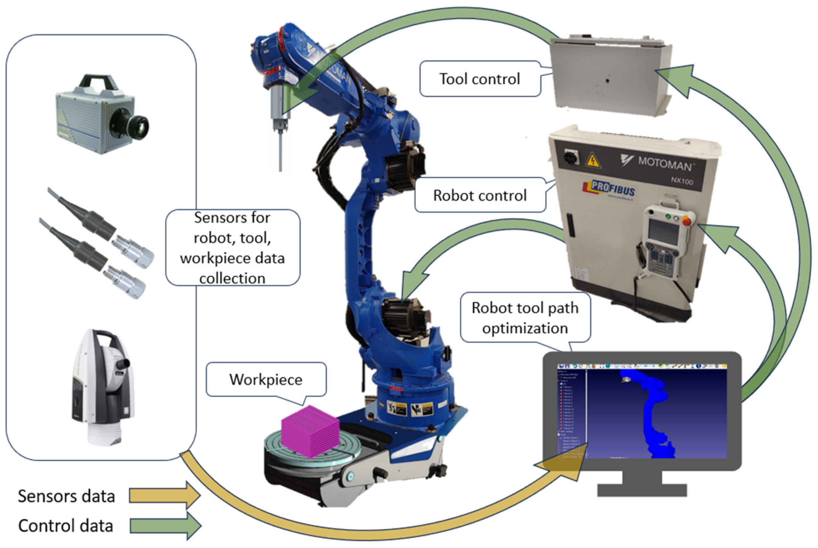
[6]. The example of industrial robotic machining adapting different sensors and control algorithms is shown in
Figure 1.
Figure 1. The example representation of industrial robotic machining.
Industrial robotic machining processes and techniques involve using such systems to perform cutting, milling, drilling, and grinding operations on various materials, such as metal, plastic, and wood
[7]. In the literature, robotic machining is classified into low material removal rate (MRR), e.g., grinding, polishing, and deburring, and high MRR operations, e.g., milling and drilling. The literature covers various topics related to the robotic machining process, including issues of robot dynamics, articulated robot configuration, tool trajectory optimization, quality, monitoring, and positioning error compensation. Low MRR research focuses on improving machining quality, while in high MRR operations, stiffness enhancement and vibration suppression are prioritized. However, no work has been reported to ensure stable and high-quality machining.
Advanced robotic techniques, such as force control or adaptive machining, optimize performance and ensure efficient material removal and machining
[8]. There are challenges of limited machining accuracy with industrial robots and the need for improved calibration and compliance error compensation methods. In recent research, those challenges can be overcome using auxiliary units, e.g., additional actuation systems or external measurement systems, to improve the performance and quality of robotic machining overall systems.
Robotic machining is a feasible alternative to conventional computer numerical control (CNC) machines for processing materials with different levels of hardness and complexity
[9]. However, the lack of rules guiding the use of robotic cells is a barrier that needs to be overcome. Some propose addressing the accuracy and quality of surface finish issues in robotic machining by studying the relative orientation of the cutting force concerning the robot’s stiffness.
The need is high for modeling and identification to optimize, plan, and control the machining process
[10]. Recent research on various machining processes includes deburring, milling, polishing, and thin-wall machining. One major limitation of robots in machining tasks is insufficient rigidity at the tool center point (TCP), which affects machining accuracy. There are some suggestions for improving robot accuracy, such as implementing intuitive programmable systems, using sensors to adapt motions to the machining task, optimizing the path planning process, and offering cloud-based machine learning algorithms for process optimization.
Most of the inaccuracies arise from the dynamic properties of the specific industrial robot
[11], tool path
[12], machined material
[13], or machined surface
[14]. Hight vibration can occur during robotic machining, leading to a poor surface finish, reduced accuracy, and tool breakage.
2. Robotic Material Processing
Robotic material processing refers to the use of robots in various industrial areas for additive and subtracting manufacturing processes, i.e., milling, grinding, drilling, polishing, etc., instead of traditional machining centers. Different processing operations and parts implementation areas have unique machining accuracy and efficiency requirements. Figure 2 shows the graphical summary of analyzed use cases regarding the material, machining operation type, and focus point of the performed research.
Figure 2. Summary of machining processes.
From Figure 2, it can be concluded that different materials were used in different robotic machining research cases to improve industrial robotic posture, path, accuracy, or stability. In most cases, aluminum alloys are used as lightweight, corrosion-resistant, and desirable strength metals.
2.1. Milling
Robotic milling offers cheap, effective, and accurate shaping operations, but in some cases, it has some limitations and requires intelligent solutions to overcome them (Table 1). The common problem in robotic milling operations is the complex relations between robots’ payload stiffness and accuracy. Robots with higher payloads are stiffer, but at the same time, they typically are less accurate. In addition, the stiffness of industrial robots is an extremely complex parameter depending on the majority of factors, including robot links configuration, the direction of gravity force, TCP position and orientation in the workspace, rigidity of each joint, etc.
Performed analysis of the reference outlines shows that that robots are more likely to chatter than regular machines due to lower stiffness
[15], and active force control can be used to prevent this
[16]. The enhancement of overall robot stiffness due to drives, body structure design, and materials is not actively ongoing.
Table 1. Summary of robotic milling.
| Problem |
Methods |
Industrial Robot |
Additional Means |
Ref. |
| Low stiffness of the robot structure |
Impact tests at many tool-tip positions to obtain modal
parameters of frequency response functions (FRFs) |
ABB IRB 6660-205 |
Sound microphone, National Instruments (NI) data acquisition system |
[17] |
| Optimal control for active vibration suppression |
Linear Quadratic Regulator (LQR) optimal control |
KUKA KR500-3 with KUKA KRC4 controller |
KUKA Robotic Sensor
Interface and EtherCAT protocol, laser tracker |
[18] |
| Machining accuracy based on stiffness properties |
Task-dependent performance index (PI) |
ABB IRB 6660-205 |
NI data acquisition
the system, laser tracker,
dynamometer |
[19] |
Stiffness increase and
machining accuracy
improvement |
Conversion from a 5-axis CNC tool path to a 6-axis industrial robot trajectory |
Motoman MH80 IR |
AT960 laser tracker,
NX 8.5 software,
Leitz PMM-XI8106 |
[20] |
Avoidance of over-cut and
interference |
Fixed cutter axis control
(F-CAC) |
Motoman-UP6 |
MATLAB-based design and simulation toolbox and ROTSY 4.2 software |
[21] |
Prediction of surface
topography |
Mapping-based intersecting method |
ABB IRB 6660-205 |
Kistler dynamometer, microphone, acceleration sensor. |
[14] |
The insufficient stiff robot structure directly impacts the milling process. It defines acceptable cutting forces. Low stiffness and low cutting force of the cutting tool can excite vibrations affecting milling, accuracy, and surface quality
[17]. A method to predict the stability of the robot manipulator during milling is provided, which is posture-dependent within the work volume. The approach involves conducting impact tests at many tool-tip positions to obtain frequency response at the corresponding robot postures and building a predictive model to construct milling stability lobe diagrams at different postures.
Another study
[18] presents an optimal control approach to active vibration damping in robotic milling integrating a six-degree-of-freedom (DOF) industrial robot. The methodology involved using pose-dependent modal parameters to formulate and solve an LQR optimal control problem for active vibration damping. The methodology allows the reduction in vibrations in X and Z directions during milling and ensures lower deviations of the machined surface. According to the authors, future generations of industrial robots are supposed to minimize actuator delay so that they could make it better to actively control and enhance milling accuracy at higher frequencies of excitation.
An alternative approach evaluating the structural stiffness of an industrial robot to improve robot milling accuracy is presented in
[19]. The authors introduced the task-dependent PI to assess the stiffness at a given robot posture. This index depends on the external acting force direction but is independent of its magnitude. In such cases, the machining process optimization goal is to maximize PI by adjusting tool orientation. A similar pose optimization method to increase stiffness and improve machining accuracy for milling robots is presented in
[20]. The method involves the conversion of a five-axis CNC tool path to a six-axis robot trajectory, taking advantage of an additional DOF. A new frame-invariant PI is proposed to evaluate the stiffness of a robot at a particular posture, and a one-dimensional posture optimization problem is formulated considering joint limits, singularity avoidance, and trajectory smoothness. A simple discretization search algorithm that can be easily added to commercial CAD/CAM software solves the formulated optimization problem, providing a solution to ensure the highest stiffness in the required trajectory.
The paper
[21] gives a solution for robotic milling surfaces of Non-Uniform Rational B-Splines (NURBS) with significantly large fluctuations, which is a usual task in the woodworking industry. The authors developed and validated the fixed cutter axis control method to avoid over-cutting problems that typically appear using the variable cutter axis control method. The required milling trajectory on a predefined NURBS surface is obtained using the NURBS mapping projection, evaluating surface curvature, and applying the equi-chord interpolation method to define a set of interpolation points.
A different approach to the increasing accuracy of robotic milling is demonstrated in research presented in
[14]. The authors developed a model to predict the surface area topography of oriented Plexiglas in industrial robotic milling, taking account of vibrations from tools. They modeled the dynamic behavior of the intersection in the cutting zones and integrated the gained vibration displacements into the sweep surfaces of the cutting edges. These data were used to model the 3D graph representing the topography of the machined surface. Performed experiments showed that the predicted and physically measured surface topography, and the model predicting the surface topography inducing the regenerative chatter, agreed well.
From the review of the literature about robotic milling, the main objective is to improve accuracy from the perspective of robotic stiffness. There were several approaches to this, such as through vibration measurements, e.g., implementing impact tests to obtain modal parameters of FRFs and adjusting the performance to the data, or laser tracking, e.g., implementing the LQR optimal control method to suspend vibrations by monitoring the amplitude.
2.2. Grinding
Robotic grinding covers performed precision material removal processes, typically using abrasive tools or wheels, to achieve desired surface finishes or remove excess material from workpieces. Some research cases on robotic polishing are summarized in Table 2.
Table 2. Summary of robotic grinding.
| Problem |
Methods |
Industrial Robot |
Additional Means |
Ref. |
| Poor grinding accuracy and surface quality |
Review on calibration and measurement, trajectory planning, force control, and surface integrity |
- |
Active/passive force
control sensors,
PID-based control |
[22] |
| Examination of curvature characteristics of complex-shaped stone products |
The matching relationship between surface characteristics and machining trajectory |
KUKA QUANTECK KR240 R2900 ultra |
Kistler’s 9170B 6-dimensional torque sensor. |
[23] |
| Free-form surface machining is limited by individual kinematic errors or joint stiffness. |
Speed and force adjoint transformation, fine-tuning the workpiece frame position |
ABB industrial robot with RobotStudio 2020.3 software |
Grinding machine with a belt, robot here is a
workpiece manipulator |
[24] |
| Profile accuracy enhancement |
Trajectory planning algorithm adapting the material removal profile (MRP) |
- |
Trajectory planning
software based on
OpenCASCADE |
[1] |
| Grinding of weak-stiffness workpieces |
Deformation and stiffness measurements and time-varying isobaric surface (TVIS) mesh generation |
Universal Robot UR5 |
Six-dimensional force sensor ATI Axia80 |
[25] |
| Increasing demands for precision and automation |
Geometric-multilevel-Line-2D method |
EFORT ER50-C10,
ABB IRB6700 |
Different shape parts,
vision system,
PC workstation
(CPU: i7, GPU: RTX 2070S, RAM: 32G) |
[26] |
Robotic grinding is assumed to be an alternative approach in complex component machining because of its flexibility, intelligence, and cost-effectiveness
[22]. The paper presents a systematic review of robotic grinding, focusing on accuracy, compliance, and cooperative control. Relevant research work and various strategies to overcome challenges are discussed here, including online measurement, allowance control, force control, and surface integrity. However, despite the technical advantages of robotic machining, there are shortcomings remaining in terms of accuracy and surface quality compared to CNC machine tools due to the high coupling of robotic performance and configuration. To further improve the robotic grinding performance capability, breakthroughs in robot calibration, monitoring, trajectory planning, force control, and surface consistency are urgently needed. According to the review authors, future studies should address parallel measurement accuracy and stability issues, splicing point cloud fragments without mark points, and using inspection software for surfaces with a common data-storage format and a unique library of validation processes.
The surface curvature characteristics of complex-shaped stone products (CSSPs) were examined, and the correlation between surface characteristics and machining trajectory was studied
[23]. The optimization of grinding force variations in the finishing process was carried out, and the optimal machining trajectory was set to improve the surface profile tolerance. Results from simulations were then experimentally verified. It was found that changing the trajectory can reduce the grinding force variations by 52.8% and the surface profile error by 36.9%. It was concluded that the surface finishing and tool axis changes with the surface direction result in lower grinding force variations in stone. The optimization effect was the most significant when machining a concave cylindrical surface, with a 63.7% reduction in fluctuation.
Despite its potential, the quality of robotic grinding for free-form surface machining is limited by individual structural errors or joint stiffness
[24]. A systematic method of error compensation, workpiece orientation optimization, and optimization of the tool pose is proposed in this article to reduce the machining error in robotic grinding, which is a viable technique for free-form surface machining. The machining error mathematical models are built using speed and force adjacent transformation, and an error compensation approach is presented by fine-tuning the workpiece position. The experiment of blade grinding is performed, and the proposed method successfully reduces the average machining error of the blade. This approach may be useful to stimulate the use of robotic belt grinding for parts with high machining quality requirements, taking into account two factors: kinematic tolerances and joint stiffness.
An adaptive trajectory planning algorithm is proposed, using an MRP model, for the robotic belt grinding of complex blades
[1]. The algorithm takes into account the elastic deformation at the contact wheel–workpiece interface and the curvature change characteristics of the free-form surface to enhance profile accuracy. According to results of simulations and experiments, the algorithm effectively solves the problem of over-cutting while reducing machining time and improving surface roughness. The average profile error is only 0.0194 mm and is within the tolerance of 0.08 mm. The controlled contact force and a variable process parameter approach suit the grinding of free-form surfaces.
In the paper from above
[25], the TVIS as a virtual surface used to generate constant force in robotic grinding of weak-stiffness workpieces was defined, including contact trial (CT) and the reconstruction of the surface. The CT process measures the deformation and stiffness of the workpiece, and a TVIS mesh is constructed for grinding path planning. Experiments show that the proposed method achieves constant grinding force and is robust to different types of workpieces and techniques. The paper’s main contributions are the automatic method to realize constant robotic grinding force, the TVIS concept for constant force grinding, and the CT process to measure the workpiece deformation and stiffness.
A robotic grinding workstation designed for precision and automation in grinding rough metal cast objects is presented in
[26]. The system employs machine vision and an industrial manipulator to address challenges in positioning and automatic grinding. The approach includes a two-step localization strategy, combining deep neural networks and template matching for precise object positioning in challenging industrial environments. Edge extraction and contour fitting techniques are used to locate and address surface imperfections, particularly burrs, on the objects. The system uses a grid method to detect and plan the grinding trajectory for the industrial manipulator, enhancing automation throughout the loading, grinding, and unloading processes. The results demonstrate the system’s stability, efficiency, and accuracy, while also overcoming material-related challenges. According to the authors, this robotic grinding station significantly improves precision, quality, and production efficiency, reducing manual labor and increasing staff safety.
2.3. Polishing
Robotic polishing involves using robotic systems and tools to achieve high-precision and efficient surface finishing, improving productivity and consistency in various industries as the final machining process. While the robotic arm allows flexible manipulation of the polishing tool, the stability of the manipulator arm is also affected by the acting forces of the tool. This impacts the machined surface quality, and force control is demanded. Several robotic polishing research cases are summarized in Table 3.
Table 3. Summary of robotic polishing.
| Problem |
Methods |
Industrial Robot |
Additional Means |
Ref. |
| Surface roughness reduction and improvement of surface quality of mold steel |
Optimizations of process parameters: polishing pressure, feed speed, and rotating speed of the tool |
KUKA KR60-3 |
Force control with a six-dimensional force sensor |
[27] |
| Surface roughness reduction of blades |
Point cloud preprocessing, slicing algorithm, and the
intersection method |
ABB IRB
1200–7/0.7 with
RobotStudio simulations |
3D profile sensor |
[28] |
| Achievement of consistent surface quality |
Contact point compensation model to predict the contact point variation |
ABB industrial robot |
Force-controlled
end-effector |
[29] |
| Desire constant force tracking control |
Impedance controller with online stiffness and reverse damping force |
7-DOF X-mate3- Pro |
Lyapunov function,
force sensor |
[30] |
| Maintenance of a constant force between the robot and the workpiece |
Constant force compliant mechanism, compared to traditional methods using force control |
7-DOF KUKA industrial robot |
Passive constant force end-effector,
K9 R467 reflective mirror |
[31] |
Achievement of constant
polishing pressure |
Preston equation and Hertz theory-based constant force mechanism |
Universal Robot UR5 |
Constant force
end-effector |
[32] |
Improvement of finishing
efficiency, surface quality, and surface consistency |
A relation model between
removal rate and polishing pressure |
Kuka KR30-3 |
Force/torque sensor |
[33] |
In the manufacturing industry, polishing is considered the final machining phase. In the research
[27], process parameters (i.e., polishing pressure, belt speed, max cutting depth) were optimized for robotic polishing to reduce surface roughness, thus improving the quality of the mold’s steel surface. The optimum range for each parameter was obtained from a single-factor experiment. Another central composite design (COD) experiment was conducted to establish a prediction model of surface roughness. Here, the COD experiment can evaluate the linear and interactive effects, such as the high-order surface effect. The polishing experiments were conducted for validation, and the experimental results showed an effective decrease in surface roughness after polishing with the optimal parameters such as polishing pressure, tool rotation speed, and feed rate. The prediction model helps improve the quality of the surface in robotic polishing. Additionally, a platform with force control was built here to realize the robotic polishing of the workpiece.
Applying thermal barrier coatings in aerospace manufacturing for aero-engine blades allows them to operate at higher temperatures with greater efficiency. However, it increases the surface roughness, which affects the thermal lifecycle and insulation performance of the coating
[28]. To reduce the roughness, an integrated robotic polishing trajectory planning method is proposed in this paper. The retrieved point cloud is preprocessed and, after that, the slicing and intersection methods are used to create a contact point set. The tool-tip positions and postures are calculated to optimize the robot’s movement, resulting in a smoother polishing trajectory. Simulation and experiments show that the coating roughness on the blade surface after polishing is reduced. Polishing is achieved with a small amount of removal, which becomes mirror-like smooth.
It is possible to use complex force-controlled end-effectors with few degrees of freedom to achieve consistent surface quality in robotic polishing. An end-effector with two rotational and one translational joints is presented in
[29]. The simultaneous control of the angle of inclination of the polishing disc and the normal contact force between the disc and the surface of the workpiece is considered to be very important. The contact point variation, caused by the changes in the angle of inclination of the end-effector’s moving platform, the disc’s geometry, and the disc’s compliance, is identified as a significant issue that reduces the accuracy of force control. A combination of force control and contact point prediction results in a new hybrid orientation/force control architecture with a contact point compensation model used to control the orientation of the tool and the contact force. Such a method significantly improved the force-tracking performance under three different angle of inclination references, reducing the mean force error by 78.9%, 81.1%, and 72.3%, respectively.
The paper
[30] proposes another constant force-tracking control scheme adapting an impedance controller in a combination of online stiffness and reverse damping force (OSRDF). The goal is to track the desired machining force. The proposed approach tracks and references the trajectory based on its reference position and velocity. This OSRDF controller is implemented by adjusting the stiffness parameter and merging the inverse damping force with the force tracking error. This is used to compensate for the properties of an unknown environment and reduce the force error to close to zero. Simulation studies and experimental tests on a robotic manipulator showed the efficiency of the proposed method.
Complex multi-degree-of-freedom tools certainly provide additional flexibility for controlling the machining process, but, on the other hand, they require more effort for accurate control. An alternative solution is passive devices maintaining the constant force between the tool and the machined object
[31]. Using the constant force tool eliminates the requirement for force monitoring and real-time control. The passive constant force end-effector was designed to provide a 40 N constant contact force, while the polishing experiment was conducted on a reflective mirror 200 mm in diameter. This showed that the passive end-effector provides stable pressure with variations within 3.43 N. The polished surface root mean square of a large-aperture reflective mirror is lower than λ/10 (where λ = 632.8 nm). Compared to traditional force control methods, the passive method provides a low-cost and trustworthy choice for robotic polishing using a constant force-compliant tool. Nevertheless, issues of the mechanisms’ stiffness remain essential points.
An original passive end-effector design based on a constant force mechanism for robotic polishing was proposed in
[32]. The end-effector regulates the contact force passively, and the motion range acts as a buffer to counteract excessive displacement induced by inertia. With no force overshoot, the surface quality of the workpiece is consistent. The experiment results show that the constant force mechanism improves the force accuracy and consistency of the polished surface.
The article
[33] describes a technology to improve finishing efficiency, surface quality, and surface consistency for robot automatic polishing on curved surfaces. A polishing platform was created, and a study established a pattern between removal rate and polishing pressure. A polishing pressure control model was also established, and factors influencing polishing were discussed. The article proposes a generation algorithm for the position and posture of the robot polishing tool, which uses force–position–posture decouple control. This is used to achieve robotic polishing that is similar to that experienced with manual constant pressure polishing. It was tested for automatic robotic polishing on bent surfaces, and the validation results showed the efficiency and feasibility of the model, as well as its ability to achieve precise surfaces. The article also introduces a gravity compensation algorithm for the polishing tool to eliminate interference caused by gravity during machining.
To summarize, there are two main objects of research in robotic polishing: surface roughness reduction and improvement in surface quality, and constant force tracking between the robot tool and the machined workpiece. One can be achieved by optimizing process parameters through force measurements or scanning the 3D profile of the surface. The other can be achieved through impedance control or a passive constant force end-effector.
2.4. Drilling
Robotic drilling refers to using a robotic system to perform drilling operations, offering accuracy, efficiency, flexibility, and increased safety in various manufacturing, construction, or aerospace industries. From the perspective of robotics, it faces similar issues to milling but raises additional requirements for tool orientation—the tool rotation axis must be kept at a constant angle during the procedure. Therefore, the main challenges for such operation are non-uniform robot stiffness and the impact of gravitational force limiting the implementation of robotic systems in some industrial areas requiring high accuracy.
The use of six-axis articulated industrial robots for drilling and trimming in aerospace manufacturing is increasing due to their flexibility, low cost, and large operating volume
[34]. However, too low structural robot stiffness and positioning accuracy limit their machining to non-critical components and parts with low accuracy requirements for surface finishing. A study was conducted to improve the capability of robotic machines to compensate for robot path errors in real time using a single 3-DOF laser tracker. The experiment significantly improved path accuracy, hole position accuracy and quality, and machined aluminum part accuracy. However, the study also showed that when compensating for the robot in real time, the largest source of residual error remains the backlash.
On the basis of vibration, a classification approach was published to detect low-quality holes caused by robotic inclined drilling in the aircraft assembly industry
[35]. The approach involves establishing a vibration model to simulate its signals during vertical and inclined drilling and training a Resnet classifier using actual and simulated signals. In that way, the drilling state is identified by inputting the signals of the intercepted stable drilling section into the Resnet. The proposed method greatly reduces manual operations and solves the problem of obtaining many set data to train deep learning methods. From the experimental results, the Resnet classifier can accurately classify vertical and inclined drilling, even if few actual signals are used.
Another analysis of robotic drilling quality, which is influenced by its stiffness, is given in
[36]. From here, drilling thrust force can cause the deformation in three directions of the manipulator, resulting in low diameter accuracy and poor hole quality. The paper proposes using a preload pressing force with a defined stiffness promotion coefficient to strengthen the stiffness of the machining plane. A model is established and the effects of pressing force are quantitatively evaluated. A matching criterion is proposed to ensure stability during drilling and, based on this, the proper pressing force value can be calculated. The experiments showed that the machining plane stiffness could be effectively improved under preload pressing force, leading to enhanced drilling stability and precision of the hole diameter.
Another study
[37] focused on accurate drilling applications, and found that a key source of errors affecting drilled holes’ quality and circularity is static friction in robot joints, especially when joints reverse direction. The study proposed an optimization framework to improve robot manipulation and achieve better machined properties of the hole. The proposed model includes a general robotic drilling manipulation with an additional DOF. Particle Swarm Optimization (PSO) is used to select the best pose throughout the motion, and experimental tests show the tool deviation envelope is reduced by 40%.
The possibilities of an industrial robot drilling with a high-speed machine tool spindle for machining aluminum 6061-T6 were investigated in a study
[38]. The hole exit burr heights and surface roughness were assessed by implementing the Taguchi design methodology, focusing on the feed rate, spindle speed, and pecking cycle. A condition monitoring system was utilized to identify the vibrations during the drilling operation and to determine which robot poses have increased stiffness. According to the authors, there is potential for further improvements, in particular with control of the drill exit force and the pecking cycles.
Recent advantages in the virtual and augmented reality fields also have a corresponding response in robotics. A digital twin framework for robotic drilling is introduced in
[39]. This is proposed based on the idea, where three entities have been defined: the device communication entity, the digital twin entity, and the user entity. The authors present a developed generic reference model to highlight elements of the digital twin architecture relevant to robotic drilling, and real-time visualization of drilling process parameters is demonstrated. According to the authors, this framework for robotized drilling may be used for virtual real-time 3D visual representations. However, developing a comprehensive digital twin covering all aspects of the robotic drilling process is costly and time consuming. However, on the other hand, such a digital twin complemented by artificial intelligence methods could be used to predict system behavior or optimize the efficiency of the process.
A summary of recent implementations and research on robotic drilling is presented in Table 4.
Table 4. Summary of robotic drilling.
| Problem |
Methods |
Industrial Robot |
Additional Means |
Ref. |
| Low structural stiffness and low positional accuracy |
Ballbar dynamic path accuracy, a series of drilling case studies, and machining tests |
KUKA KR120R2500 PRO with a KUKA KR C4 controller |
Single 3-DOF laser tracker |
[34] |
| Detection of unqualified holes caused by inclined drilling |
Vibration-based classification |
UR industrial robot |
Resnet classifier with
vibration model, camera |
[35] |
| Robot stiffness influence on drilling quality |
Preload pressing force to strengthen the stiffness of the machining plane |
KUKA industrial robot |
ZEISS SPECTRUM II Coordinate measuring machine |
[36] |
| Static friction in robot joints impacts the quality |
Optimization framework, which models a general drilling motion minimizing joint reversals |
KUKA KR 6 R700-2 |
Particle Swarm Optimization |
[37] |
| Hole surface roughness and exit burr heights |
Taguchi design methodology |
Kuka KR16 |
CNC milling machine as a reference, SignalCalc Ace Vibration sensors |
[38] |
| A unified digital twin framework for the manufacturing environment is missing. |
Generic reference model to highlight elements of the digital twin |
KUKA KR210 R3100 Ultra with a KRC4 controller |
Based on ISO 23247 standard, the drilling and vision module |
[39] |
In conclusion, stiffness is a research target that is similar to previous targets in the field of robotic drilling, and another research target is drilled hole quality. Some propose using preload pressing force, whereas others simulate vibration signals and train a Resnet classifier using actual and simulated signals identifying the drilling states, thus minimizing the resources needed for computation. For example, a study has been carried out by comparing CNC drilling and robotic drilling, and showed that using the Taguchi design methodology for the latter can improve machining quality.
2.5. Other Cases
Robotic material processing is not limited only to traditional machining operations. There are a lot of other less used cases, such as chamfering, deburring, or boring, which require robotic tool path accuracy to achieve the best quality and efficiency. According to
[40], robotic deburring is a suitable and cheaper alternative because of its flexibility and the use of laser, vision, and force control sensors. In addition, Ref.
[41] puts forward a robotic tool study as a key factor for a better chamfering quality. The summary of some of the most interesting cases is presented in
Table 5.
Table 5. Summary of other machining cases in robotics.
| Problem |
Methods |
Industrial Robot |
Additional Means |
Ref. |
| Poor positioning accuracy |
Force control |
ABB IRB-4600 |
Cone-shape stone tool, Omega 85 force-torque sensor, AFD 310 compliant device, spindle,
robot operating system (ROS) |
[42] |
The need for suitable force
prediction |
Linear regression method,
exponential model based on the simplex search method |
Unspecified six-DOF robot |
Force-torque sensor, laser scanner, spindle, aluminum 6061 workpiece |
[43] |
| Poor quality and efficiency of the hole |
Prediction based on measured force, intrinsic mode functions, empirical mode decomposition, Hilbert transform, and spectrum |
ABB-IRB6600 |
Kistler9257B dynamometer, end-effector, mobile platform, control system |
[44] |
The paper
[42] describes a method for robotic gear chamfering that avoids the use of expensive and time-consuming measuring devices for more accurate positioning, registration, and fixing of the workpiece. Because of the uncertainty of the workpiece orientation and location, authors employ chamfering trajectory generation and force together with motion control strategies to identify the center and root positions of the gear. The method uses a compliant device, which can help to keep contact between the tool and workpiece edges and also helps to keep the force along the axis. The results showed that the proposed system has an effect in terms of chamfer machined quality and chamfer machined width, setup time, and registration time reduction. The paper also presents the relationship between compliant force and chamfer width at a fixed spindle speed of 5250 RPM.
Another study focused on robotic deburring and intended to compare the two methods’ performances to identify the suitable predicted forces during the machining of parts having areas of less than 1 mm
[43]. One method used for the research is the linear regression method and the other is simplex; these methods were used based on measured machining parameters, such as spindle speed, feed rate, feed per tooth (FPT), and cut depths (tool immersions) to produce force estimates. Tests were performed by implementing two sets, where in the first one the FPT was constant and in the second the FPT was linearly increased. Experiments were performed in practice with a six-DOF robot and forces were measured with a force–torque sensor, which was mounted between the last robot joint and the spindle. Both methods demonstrated successful prediction results—the linear method was four times more accurate in full tool immersion, whereas the exponential model showed better results, with a material removal that was eight times lower.
Ref.
[44] introduces a new method for identifying and predicting chatter in an industrial robotic boring system. Chatter is a common issue that affects the quality and efficiency of the boring process. The method involves three steps. First, the two decompositions of the measured force signal into intrinsic mode functions (IMFs) and a residue using the empirical mode are performed. Then, the Hilbert transform is applied to each IMF to obtain instantaneous frequencies and magnitudes, creating a Hilbert–Huang spectrum of the original signal. Lastly, chatter features are extracted by analyzing the Hilbert spectrum of each IMF and chatter symptoms are detected using statistical methods. Experimental results demonstrate that this approach can predict chatter up to 0.6 s before it occurs, aiding in subsequent chatter suppression and improving the workpiece’s surface quality. Additionally, the study found that the vibration frequency in a robotic boring system varies from low to high when chatter occurs, unlike standard machine tool systems where the frequency changes from high to low.
 +1 credit