 +1 credit
| Version | Summary | Created by | Modification | Content Size | Created at | Operation |
|---|---|---|---|---|---|---|
| 1 | George Anka | -- | 1882 | 2023-12-01 09:34:22 | | | |
| 2 | Catherine Yang | Meta information modification | 1882 | 2023-12-01 09:50:02 | | |
Video Upload Options
A temporary anchorage devices (TADs) surgical guide is a guide that allows a dental surgeon to place TAD in a precise, pre-planned location to give the ideal depth, angulation, and screw size to fit the area for anchorage purposes. The purpose of anchorage in orthodontics is to move a tooth or teeth for dental and alveolar orthopedic purposes. The TAD number of the screw that can be placed using the surgical guide may range from one to multiple, depending on the purpose of the anchorage needed. The surgical guide is made from hard materials like acrylic or metal. The TAD surgical guide is positioned over the adjacent teeth to maintain stability during the maneuver. The surgical guide is created using CAD/CAM technology and a 3D printer.
1. Introduction
Temporary anchorage devices (TADs) have gained importance in orthodontic practice during the past 20 years. TADs are now recognized as one of the most efficient ways to anchor dental units and reduce the need for extraction and surgical treatments. Surgical trauma and root collusion issues have negatively impacted the use of TADs during placement [1][2][3][4][5][6][7][8][9][10][11]. One way to ensure the safe placement of TADs is by using surgical guides. The making of surgical guides is possible with technological innovations. Most pioneers of surgical guides come from those who have been using the dental implant technique for decades [12][13][14]. The placement of single-standing or more TADs is facilitated by a surgical guide, which is crucial for safe clinical practice. The affordability of 3D printers and the advanced application of CAD/CAM technology have enabled the creation and manufacturing of surgical guides.
Multiple papers have addressed the issue of successful and unsuccessful TAD usage. Trauma to the tooth's root and damage to the periodontal membrane can be caused by the placement itself, which is one of the critical areas [15]. Unwanted complications can arise during inter-root placement. Typically, the TAD has a 1.4 to 1.8 mm diameter, but the interdental bone may not have enough space to accommodate this size [16][17][18].
It is common to place TADs in interdental bone or other secure locations in the maxilla and mandible. The safety and stability of TADs during dental movements depend on their accurate placement without hindering dental roots and other structures. By having complete control over the placement, an orthodontist can conduct orthodontic biomechanics in an organized and optimized manner, resulting in reduced treatment duration and better quality of treatment outcome [19].
2. The Surgical Guide for TAD
A surgical guide for TADs is intended to reduce orthodontist challenges, and designing the procedure for practical use in daily orthodontic practice will benefit both patients and the orthodontist practitioner.
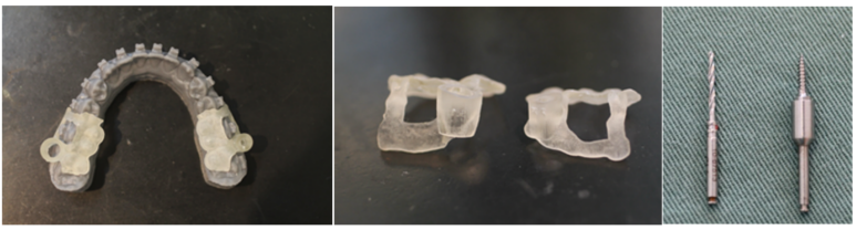
Figure 1. (a) are the surgical guides on the model; (b) are two kinds of surgical guides; (c) is the drill and the TADs.
Figure 1a and Figure 1b show the surgical guides received from the laboratory. The surgical guides were placed on the model to check for accuracy before inserting them into the mouth. There are two kinds of surgical guides for each side of the mandible. The left side is the surgical guide for the TAD, and the right is the surgical guide for the pilot drill (Figure 1b). The surgical guide is viewed from the side and should be analyzed for the vertical height, which is the most critical part, as it should be adjusted whenever a problem arises before placement, as shown in Figure 1b. The two surgical guides are needed because the size of the drill and the driver are different (Figure 1c).
The surgical guide is made by using the Dicom data from the CBCT and overlaying it with the SLT data from the intra-oral scan.
The collaboration between the laboratory technician and the clinician is necessary to make an excellent surgical guide.
The surgical guide can be used to almost perform TAD placement on the maxilla and mandible.
The TAD area is typically placed as follows:
3. In the Maxilla
The alveolar buccal region of the maxilla. The TAD placement is advantageous for the attached gingiva, but the cervical area of the tooth is not a strategic location for inserting forces. The TAD must be close to the apex of the tooth, but it's important to avoid flabby mucosa [20]. The most suitable placement is at the boundary between the attached gingival and flabby gingival areas. Special attention should be given to the positioning of the Zygomatic bone as it is located on a flabby mucosal surface. The intraoral scan will record the flabby mucosa while it is stretched. The insertion of the TAD should be done while the mucosa is compressed. It is necessary to double-check the surgical guide by manually comparison to the maxillary model.
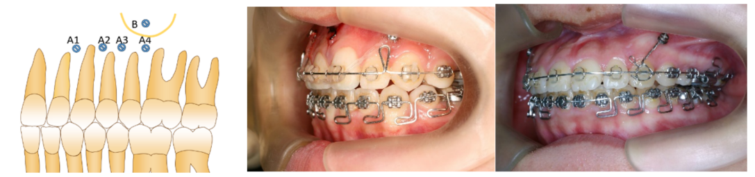
Figure 2. Figure 2a shows the interdental placement (A1, A2, A3, and A4) [21], and Figure B indicates the placement of the zygomatic bone. A buccal frenulum can make it difficult to place in the zygomatic area. In clinical practice, a frenectomy is intended to smooth the placement of TADs and prevent soft tissue ulceration when using them. Figure 2b shows anterior placement between the laterals and the canines; this area benefits intruding anterior teeth in deep bites and treating Gummy Smile [22]. Figure 2c shows the use of anchorage to retract the entire anterior region of the teeth as an en-mass movement.
TADs can be placed strategically in the palatal bone, which is a large and relatively flat area. The palatal bone makes it possible to use a super mucosal plate, such as the Benefits system [23], which may require two TADs. The surgical guide will provide the placement of two screws parallel to each other, which is difficult in the free-hand placement of TADs.
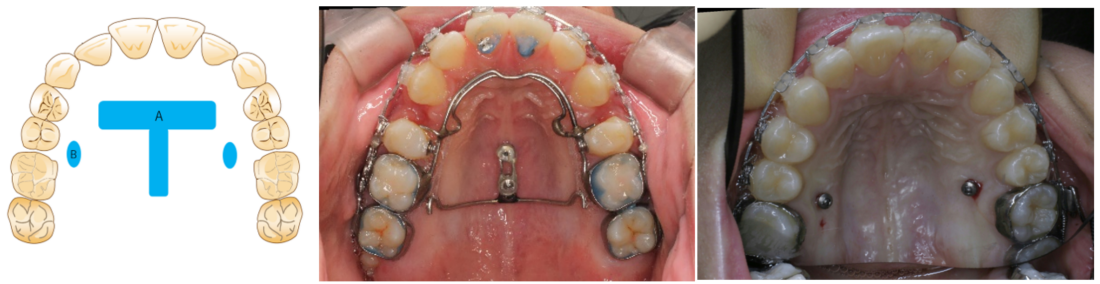
Figure 3. Figure 3a demonstrates (A) a T-shaped region [24] that provides sufficient bone volume and thickness in the palatal bone. To place TADs, CBCT data is necessary to determine the areas with sufficient Hounsfield value (Hu). The anterior region of the T-form is located transversely at the anterior portion of the hard palate. The T-form vertical area is a palatal suture that connects the left and right portions of the palatine processes, and it is also called the median suture. A parallel TAD placement may be necessary to make plate setting easier. The use of a surgical guide can enhance this approach. However, paralleling the TADs may not be necessary, depending on the device used.
Between the second bicuspid and the first molar is where the B area of the palate is located. Area B provides enough width for the TAD to be inserted into an average case. The alveolar bone is where the second bicuspid root goes vertically, and the first molar only has a single palatal root. Therefore, the B area has sufficient space for inserting the TADs. The molar and bicuspid roots can avoid colliding with the TAD during tooth movement.
In Figure 3b, the image shows a Benefit plate fixed to the vertical T-form, which serves as an anchor for the en-mass movement of all the upper teeth. The transpalatal arch is built upon the foundation of the first molars. Caution should be taken in individuals with a low maxillary sinus, which could occur in individuals with chronic allergic or other nasal diseases. Sinusitis can potentially cause bone resorption between the roots of the posterior molars. Choosing a suitable place and finding a new insertion site is essential.
4. In the Mandible
TAD use is more complex than maxillary use due to the U-shaped configuration and tongue located in the middle of the mandible. Due to the shallow lower buccal fold, some individuals may find it difficult to place the TAD. During eating, the food will descend to the buccal and lingual sides of the posterior teeth and then be retrieved by the tongue. The mucosa of the cheek and buccal frenulum is bound to move during this maneuver. The mucosa may be harmed by TAD placement [25].
The placement of TAD on the alveolar buccal region is in the interdental area, between the attached gingiva and the flabby gingiva. The lower lip's activity depends on the oral muscular structure and age. It is essential to avoid placing it on the buccal alveolar bone in front of the four incisors as the consequences of mucosa ulceration are high.
Placement of TAD behind the canine is less irritating to the mucosa.
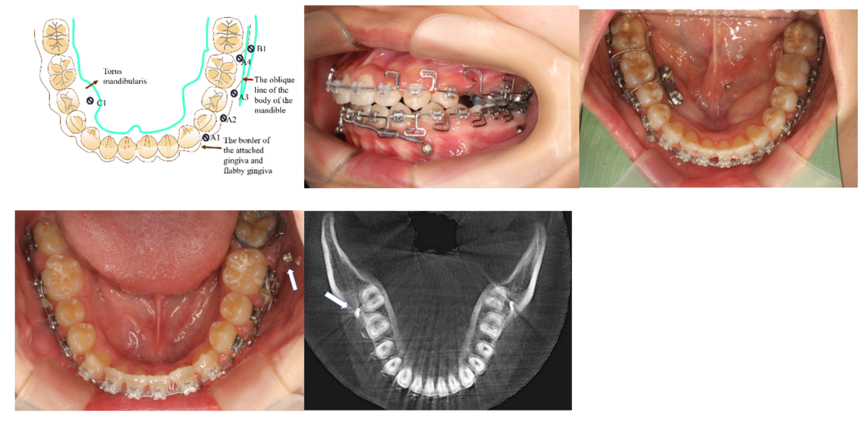
Figure 4. Figure 4a shows the use of TAD in the mandible; A1 to A4 are interdental placements. B1 is located on the oblique line of the mandible body. En-massed retraction of all teeth in the mandible requires placement on the B1 area [26]. C1 is the place for the TAD in the torus mandibularis. Torus mandibularis is uncommon in many patients and its size can vary from patient to patient. When the torus mandibularis is big enough to fit TAD, it can also serve as an anchorage for moving teeth from the lingual side. Figure 4b shows the use of TAD at location A1, which is between the canine and the first bicuspids. The objective is to connect a coiled spring called a propeller [27][27]. The midline and arch form of the anterior lower teeth alignment will be corrected by moving the anterior teeth with the propeller. Figure 4b also shows the TAD location at A4. The goal of the A4 TAD location is to move the teeth distally. A collision between TAD and the root of the teeth can occur after teeth move for a few mm. When teeth move over a long distance, it is necessary to have TAD placement on B1 (Figures 4d and 4e). The ridge known as the oblique line of the mandible is located between the anterior border of the mandibular ramus and the lower molar region. The optimal location for TAD placement can be identified by palpating the buccal area of the molars and comparing it to the CBCT data. The most suitable place is typically in front of the mesial root of the second molar. The bone's thickness is sufficient to provide room for the TAD placement, almost parallel to the molar root. Placement will be easier with a surgical TAD guide due to the steepness of the B1 area on the body of the mandible. Figure 4c shows the location of TAD on C1. The torus mandibularis can be effectively used with single-standing TAD of double parallel TADs with a plate as figure 4c, where the posterior width of the lower arch can be constricted. Figure 4d shows the TAD at the B1 location. The flabby mucosal area close to the cheek mucosa makes it crucial to choose the right area for B1. The use of a surgical guide is essential. To prevent the initial bur from catching the mucosa, it is crucial to make sure that the bottom area of the TAD surgical guide presses and holds the mucosa. The TAD surgical guide cannot be justified in this B1 case solely based on the SLT data. An impression is necessary to create a model. The model allows for adjustment of the area where the TAD surgical guide touches the mucosal. Drilling requires the mucosa to be lightly compressed.
The TAD surgical guide can be effectively utilized in all the areas mentioned, regardless of how TAD is placed on the maxilla and mandible.
References
- Ahmed V KS, Rooban T, Krishnaswamy NR, Mani K, Kalladka G. Root damage and repair in patients with temporary skeletal anchorage devices. Am J Orthod Dentofacial Orthop. 2012 May;141(5):547-55. doi: 10.1016/j.ajodo.2011.11.014.
- Çelik Güler Ö, Malkoç S. Effects of orthodontic force on root surface damage caused by contact with temporary anchorage devices and on the repair process. Korean J Orthod. 2019 Mar;49(2):106-115. doi: 10.4041/kjod.2019.49.2.106. Epub 2019 Mar 19.
- Marc Schätzle, Roland Männchen, Marcel Zwahlen, Niklaus P. Lang Survival and failure rates of orthodontic temporary anchorage devices: a systematic review Clinical Oral Implants Research 09 November 2009 Wiley.
- Chen YJ, Chang HH, Lin HY, Lai EH, Hung HC, Yao CC. Stability of miniplates and miniscrews used for orthodontic anchorage: experience with 492 temporary anchorage devices. Clin Oral Implants Res. 2008;19(11):1188-1196. doi:10.1111/j.1600-0501.2008.01571.x.
- Manuel Nienkemper, Björn Ludwig, Risk of root damage after using lateral cephalogram and intraoral scan for guided insertion of palatal miniscrews, Head & Face Medicine, 10.1186/s13005-022-00335-0, 18, 1, (2022).
- Elena Riad Deglow, Miriam O′Connor Esteban, Álvaro Zubizarreta-Macho, Sofĺa Hernández Montero, Georgia Tzironi, Francesc Abella Sans, Alberto Albaladejo Martínez, Novel digital technique to analyze the accuracy and intraoperative complications of orthodontic self-tapping and self-drilling microscrews placement techniques: An in vitro study, American Journal of Orthodontics and Dentofacial Orthopedics, 10.1016/j.ajodo.2021.03.020, 162, 2, (201-207), (2022).
- Sarah Abu Arqub, Vaibhav Gandhi, Shivam Mehta, Ledjo Palo, Madhur Upadhyay, Sumit Yadav, Survival estimates and risk factors for failure of palatal and buccal mini-implants, The Angle Orthodontist, 10.2319/090720-777.1, 91, 6, (756-763), (2021).
- Amin Golshah, Kimia Gorji, Nafiseh Nikkerdar, Effect of miniscrew insertion angle in the maxillary buccal plate on its clinical survival: a randomized clinical trial, Progress in Orthodontics, 10.1186/s40510-021-00370-8, 22, 1, (2021).
- Amin Golshah, Mahya Salahshour, Nafiseh Nikkerdar, Interradicular distance and alveolar bone thickness for miniscrew insertion: a CBCT study of Persian adults with different sagittal skeletal patterns, B.M.C. Oral Health, 10.1186/s12903-021-01891-8, 21, 1, (2021).
- Diana Milena Ramírez-Ossa, Natalia Escobar-Correa, Maria Antonia Ramírez-Bustamante, Andrés A. Agudelo-Suárez, An Umbrella Review Of The Effectiveness Of Temporary Anchorage Devices And The Factors That Contribute To Their Success Or Failure, Journal of Evidence Based Dental Practice, 10.1016/j.jebdp.2020.101402, (101402), (2020).
- Barbara Kirnbauer, Petra Rugani, Elisabeth Santigli, Philipp Tepesch, Kamran Ali, Norbert Jakse, Fully guided placement of orthodontic miniscrews— a technical report, Australasian Orthodontic Journal, 10.21307/aoj-2020-035, 35, 1, (71-74), (2021).
- Vercruyssen M, Laleman I, Jacobs R, Quirynen M. Computer-supported implant planning and guided surgery: a narrative review. Clin. Oral Impl. Res. 26 (Suppl. 11), 2015, 69–76.
- Hämmerle CHF, Cordaro L, van Assche N, Benic GI, Bornstein M, Gamper F, Gotfredsen K, Harris D, Hürzeler M, Jacobs R,Kapos T, Kohal RJ, Patzelt S.B.M., Sailer I, Tahmaseb A, Vercruyssen M, Wismeijer D. Digital technologies to support planning, treatment, and fabrication processes and outcome assessments in implant dentistry. Summary and consensus statements. The 4th E.A.O. consensus conference 2015. Clin. Oral Impl. Res. 26 (s11), 2015, 97–101.
- Apostolakis, D., Kourakis, G. CAD/CAM implant surgical guides: maximum errors in implant positioning attributable to the properties of the metal sleeve/osteotomy drill combination. Int J Implant Dent 4, 34 (2018).
- Cho WH. Influence of the operator's experience and drilling sites on the root contact during drilling for micro-implants insertion [thesis]. Daegu, Korea: Kyungpook University; 2005.
- Kuroda S, Yamada K, Deguchi T, Hashimoto T, Kyung H-M, Takano-Yamamoto T. Root proximity is a major factor for screw failure in orthodontic anchorage. Am J Orthod Dentofacial Orthop. 2006.
- Arisan V, Karabuda CZ, Mumcu E, Özdemir T. Implant positioning errors in freehand and computer-aided placement methods: a single-blind clinical comparative study. Int J Oral Maxillofac Implants. 2013 JanFeb;28(1):190-204. doi: 10.11607/jomi.2691. PMID: 23377066.
- Willmann, B. Wilmes, D. Drescher, Düsseldorf, Digitale Mini-Implantat getragene Suprakonstruktionen – Design und Workflows J. Compr. Dentof. Orthod. + Orthop. (COO) Umf. Dentof. Orthod. u. Kieferorthop. (UOO) No. 3-4 / 2019 (c).
- Willmann, B. Wilmes, D. Drescher, Clinical use of digital Workflow Exemplified by Mini Implant. Inf. Orthod Kieferorthop 2020; 52: 121-127.
- Kim JH, Park YC. Evaluation of mandibular cortical bone thickness for placement of temporary anchorage devices (TADs). Korean J Orthod. 2012 Jun;42(3):110-7. doi: 10.4041/kjod.2012.42.3.110.
- Kim HJ, Yun HS, Park HD, Kim DH, Park YC. Soft-tissue and cortical-bone thickness at orthodontic implant sites. Am J Orthod Dentofacial Orthop. 2006;130(2):177-182. doi:10.1016/j.ajodo.2004.12.024.
- J.JL. Liauw, Application of TADs in an Adult Gummy Smile Case with Vertical Maxillary Excess. Book-Wiley: J.H. Park 21 February 2020 doi.org/10.1002/9781119513636.ch59.
- W, Benedict, B. Ludwig, S. Vasudavan, M. Nienkemper, Dresher. The T-Zone: Median vs. Paramedian Insertion of Palatal Mini Implants: JCO. L. 545. (2016).
- W. Benedict, R.D. Gabriele, G. Dallantula, N. Taraff, B. Ludwig. “Bone First” Principle with CAD/CAM Insertion Guides for Mini-ImplantAssisted Rapid Palatal Expansion. JCO March 2022.
- Sreenivasagan S, Subramanian AK, Selvaraj A, Marya A. Pain Perception Associated with Mini-Implants and Interventions for Pain Management: A Cross-Sectional Questionnaire-Based Survey. Biomed Res Int. 2021 Nov 29;2021:4842865. doi: 10.1155/2021/4842865. PMID: 34881334; PMCID: PMC8648475.
- Petrey JS, Saunders MM, Kluemper GT, Cunningham LL, Beeman CS. Temporary anchorage device insertion variables: effects on retention. Angle Orthod. 2010 Jul;80(4):446-53. doi: 10.2319/070309-376.1. PMID: 20482347; PMCID: PMC8966450.
- G. Anka Management of missing teeth using Temporary Anchorage Devises. Chapter 10. P223-236. R. Nanda Temporary Anchorage Devices in orthodontics. Elsevier 2008.


