Your browser does not fully support modern features. Please upgrade for a smoother experience.
Submitted Successfully!
 +1 credit
Thank you for your contribution! You can also upload a video entry or images related to this topic.
For video creation, please contact our Academic Video Service.
| Version | Summary | Created by | Modification | Content Size | Created at | Operation |
|---|---|---|---|---|---|---|
| 1 | Jia Yao | -- | 5679 | 2023-11-24 09:22:18 | | | |
| 2 | Lindsay Dong | Meta information modification | 5679 | 2023-11-27 09:54:01 | | |
Video Upload Options
We provide professional Academic Video Service to translate complex research into visually appealing presentations. Would you like to try it?
Cite
If you have any further questions, please contact Encyclopedia Editorial Office.
Li, G.; Yao, J. Snap-Off during Imbibition in Porous Media. Encyclopedia. Available online: https://encyclopedia.pub/entry/52021 (accessed on 23 June 2026).
Li G, Yao J. Snap-Off during Imbibition in Porous Media. Encyclopedia. Available at: https://encyclopedia.pub/entry/52021. Accessed June 23, 2026.
Li, Guihe, Jia Yao. "Snap-Off during Imbibition in Porous Media" Encyclopedia, https://encyclopedia.pub/entry/52021 (accessed June 23, 2026).
Li, G., & Yao, J. (2023, November 24). Snap-Off during Imbibition in Porous Media. In Encyclopedia. https://encyclopedia.pub/entry/52021
Li, Guihe and Jia Yao. "Snap-Off during Imbibition in Porous Media." Encyclopedia. Web. 24 November, 2023.
Copy Citation
The phenomenon of snap-off during imbibition in porous media, a fundamental two-phase fluid flow phenomenon, plays a crucial role in both crude oil production and carbon dioxide (CO2) utilization and storage. In porous media where two phases coexist, the instability of the phase interface may give rise to various displacement phenomena, including pore–body filling, piston-like displacement, and snap-off. Snap-off, characterized by the generation of discrete liquid droplets or gas bubbles, assumes paramount significance.
snap-off
multiphase fluid flow
imbibition
porous media
1. Introduction
Imbibition during oil reservoir exploration is a universally present and crucial process, where a nonwetting phase is displaced by a wetting phase within porous media [1][2][3]. Specially, when there are two immiscible liquids present within porous media, capillary forces drive the wetting phase to infiltrate, displacing the initial nonwetting phase. Imbibition, as a primary mechanism for displacing crude oil, plays a pivotal role, particularly in heterogeneous oil reservoirs [4][5][6] and heavy oil-recovery processes [3][7][8][9]. By influencing the flow and distribution of fluids, imbibition significantly impacts crude oil-recovery rates. The competition between viscous forces and capillary forces has been verified as the cause of imbibition [10][11][12]. In particular, capillary forces induced by surface tension promote the spontaneous movement of the wetting phase within narrow channels, while viscous forces determined by liquid viscosity and flow velocity hinder the flow of the nonwetting phase within pores. Under different types of porous media and fluid conditions, the relative magnitudes of capillary forces and viscous forces vary, thus affecting the efficiency and outcomes of the imbibition process [10][13][14]. This ultimately results in different characteristics of imbibition under various reservoir and rock conditions.
Imbibition, with its distinct characteristics, can be further categorized into three categories: quasistatic imbibition, spontaneous imbibition, and dynamic forced imbibition. In quasistatic imbibition [15][16], the process involves promoting imbibition by gradually diminishing the impact of capillary forces. Specially, capillary forces are altered by adjusting external conditions or medium properties, thereby influencing the progression of imbibition. Spontaneous imbibition [4][13] is an outcome that occurs independently of external conditions. In this scenario, imbibition is propelled solely by the interaction of various forces within the medium, without any external interference. Dynamic forced imbibition [12] occurs when an external force is deliberately applied to inject a wetting phase into subsurface porous media, displacing the nonwetting phase. In this case, the imbibition process is significantly influenced by an external force. Due to differences in the flow direction, imbibition processes can be further classified into two categories: cocurrent imbibition and countercurrent imbibition. When cocurrent imbibition occurs, the nonwetting phase is displaced by the wetting phase, which flows in the same direction as it does [17][18]. Conversely, countercurrent imbibition occurs when the flow of the nonwetting phase within the porous media is the opposite the flow of the wetting phase [19][20][21]. These distinct types and flow directions of imbibition processes yield diverse effects on the ultimate oil recovery during practical oil reservoir exploitation.
In porous media where two phases coexist, the instability of the phase interface may give rise to various displacement phenomena during the imbibition process. Typical phenomena include piston-like displacement, pore–body filling, and snap-off. The imbibition process allows the wetting phase to efficiently ingress and continuously displace the nonwetting phase in porous media with wide-ranging continuous-flow pathways. This displacement results in the formation of a piston-like front that progressively advances along the flow pathways in porous media, and this phenomenon is known as piston-like displacement [22]. When small pores are present within porous media, the wetting phase can fully occupy these pores during imbibition, entirely displacing the nonwetting phase. This phenomenon is known as pore–body filling [23]. When porous media contain flow pathways characterized by intricate geometric configurations or narrow constrictions, localized fluid pinching may occur at these constrictions as the wetting phase penetrates to displace the nonwetting phase. Then, snap-off is the term for the phenomena when discrete small droplets are formed as a result of this pinching [24]. These three phenomena result from the interaction between the wetting phase and the nonwetting phase during the imbibition process, influenced by factors such as the geometric structure of the porous media, fluid properties, and flow conditions. Piston-like displacement and pore–body filling are generally regarded as beneficial for the crude oil-recovery process, since they effectively displace the nonwetting phase within porous media. On the contrary, snap-off, characterized by the generation of discrete small droplets that trap the nonwetting phase within narrow constrictions, poses challenges to achieve complete displacement. Consequently, it is generally regarded as unfavorable for conventional oil production.
2. Mechanisms of Snap-Off
The occurrence of snap-off was initially noted during investigations of fluid transport within porous media in the early 1960s [24][25]. This phenomenon encompasses the snap-off of gas bubbles in the presence of water, as well as the snap-off of oil droplets in the context of oil–water coexistence.
Snap-off of gas bubbles was initially documented in 1961 within porous media where gas and water coexist [26]. Fried observed gas bubbles resulting from the snap-off phenomenon and proposed two processes for it: (1) Snap-off occurs when gas flows through a liquid-filled constriction, causing a new bubble to form. (2) When a long gas bubble transits through a liquid-filled constriction, snap-off ensues, resulting in the division of the long gas bubble into smaller gas bubbles. Subsequently, in 1962, Goldsmith and Mason observed and recorded bubbles generated through snap-off at the narrow gap of a cylindrical capillary [27]. They created an artificial narrow-gap structure by connecting capillaries with cross-sectional radii of 0.1 cm and 0.4 cm. Later, Mast [28] and Ransohoff et al. [29] conducted more comprehensive investigations into the snap-off phenomenon when both gas and water were present. Mast conducted experiments by using etched-glass micromodels, which featured a constricted section with a smaller cross-sectional area than the rest of the model. These models were saturated with a detergent solution, and gas was subsequently introduced to observe changes in the gas–liquid interface when both phases were present. The results of the experiments revealed notable changes in the gas–liquid interface at the constricted region, which caused gas bubbles to form. It is important to note that these bubbles could potentially become trapped at the constriction. Consequently, flow patterns were modified due to variations in the resistance to the flow in different directions through the porous network, subsequently affecting capillary resistance and resulting in the regeneration of smaller gas bubbles within the blocked constriction.
Roof observed oil droplets formed through snap-off during waterflooding experiments in 1970 [24]. In this experiment, glass tubing with circular cross-sectional pore–throat structures was utilized to replicate the waterflooding process within water-wet media, and the snap-off phenomenon was observed, wherein oil was displaced from the channel walls by water, ultimately leading to the formation of discrete oil droplets. The glass tubing used in the experiment had undergone treatment with a hydrofluoric acid solution to render it water-wet. During this snap-off process, water formed a film that spread along the tube walls, displacing the oil phase to the center of the tube and forming a symmetrical collar-shaped oil–water interface within the narrow constriction. The collar-shaped interface destabilized as water continued displacing oil, gradually reducing its diameter to zero and leading to the snap-off-induced small oil droplets. This visual experiment provided a comprehensive documentation of snap-off oil droplet formation. It emphasized that, as two-phase fluids flowed from wider tube sections into narrow constrictions, the curvature radius of the two-phase fluid interface underwent significant changes. At this juncture, the interfacial curvature exceeded that observed in other sections of the tubing system.
Based on these early experimental studies, the mechanisms underlying snap-off encompass variations in the curvature radius of the two-phase fluid interface within confined regions and the impact of capillary pressure. These mechanisms give rise to the instability of the collar-shaped interface of the two-phase fluids, ultimately resulting in the occurrence of the snap-off phenomenon within the narrow constriction.
Moreover, when comparing early investigations dating back to the 1960s with recent research endeavors, it is evident that experimental snap-off research has undergone a substantial shift as due to improvements in manufacturing and visualization techniques. This evolution has transitioned the paradigm from employing centimeter-scale experimental models to adopting micron-scale platforms. Consequently, these advancements have contributed to experimental investigations that better emulate real-world scenarios. In the realm of numerical investigations on snap-off, the ever-increasing computational capabilities and ongoing refinements in relevant algorithms have collectively led to increasingly accurate and detailed microscale simulations. These simulations are tailored to represent multiphase flow within porous media, all within more confined temporal and spatial dimensions. This precision in microscale simulations enhances the realism and applicability of the findings.
3. Influencing Factors of Snap-Off
The aforementioned studies on the snap-off mechanism indicate that the occurrence of snap-off involves the influence of specific factors, which is ultimately manifested visually through changes in the curvature radius of the two-phase fluid interface within narrow regions and the influence of capillary pressure. The interface curvature radius stands as a fundamental property parameter governing the interfaces between distinct phases, symbolizing the degree of curvature induced by interphase interactions. Capillary pressure signifies the difference in pressure between the wetting and nonwetting phases. Notably, the interface curvature radius and capillary pressure, both pivotal parameters within the snap-off mechanism, can be directly correlated through the Young–Laplace equation [30][31], presented as Equation (1), where r1 and r2 represent the principal radii of curvature (one along horizontal axis and vertical axis), Pi and Pj denote the pressures of the phases on either side of the interface, and σij signifies the interfacial tension.
In this context, interfacial tension is primarily governed by the properties of the two-phase fluids. Furthermore, the variation in the curvature radius of the interface is elucidated through the consideration of the two principal radii of curvature. While the curvature radius serves as a scalar value characterizing the mean curvature of the interface, the principal radii of curvature provide a more nuanced depiction of the local curvature in two mutually perpendicular directions. It is noteworthy that the radii of curvature of the interface are influenced not only by the intrinsic properties of the two-phase fluids but also by the intricate interplay with the attributes of porous media through which the fluid traverses, encompassing factors like wettability and geometric properties.
3.1. Characteristics of Multiphase Fluids
3.1.1. Capillary Number
The capillary number (Ca) is a dimensionless number used to describe the flow behavior of fluids within capillaries or small channels [32][32]. It is defined as Equation (2), where μ represents the viscosity of the continuous phase or the wetting phase in the two-phase fluid, V signifies the characteristic shear rate (a product of shear rate and droplet radius), and σij stands for the interfacial tension between the continuous (wetting) and dispersed (nonwetting) phases.
The capillary number represents the relative effect of viscous force to interfacial tension force in fluids and holds particular significance in multiphase flows [33]. Its magnitude influences fluid behavior under various flow conditions and is commonly employed to describe liquid flow and interface phenomena, including snap-off, within porous media. Regarding the snap-off event, viscous forces are typically observed to be the driving force, whereas interfacial tension forces are the resisting force [34]. This implies that a higher capillary number amplifies the influence of viscous forces in the continuous phase (wetting phase), facilitating the stretching and deformation of the dispersed phase.
The snap-off phenomenon occurs within a specific range of capillary numbers [35][36]. Tsai and Miksis investigated how snap-off was affected by the capillary number [37]. Using simulation methods, they determined two critical values of the capillary number that indicate when snap-off occurs. When the capillary number falls below the first critical value, a thin layer of wetting-phase film forms on the wall of the porous media, and the liquid flows slowly toward the narrow constriction. In such a scenario, the snap-off phenomenon can still occur, but requires a longer time to manifest. If the actual capillary number falls within the range defined by the first and second critical values, snap-off can occur more rapidly. When the capillary number is higher than the second critical threshold, the liquid spends very little time in the constriction, which is insufficient for the snap-off phenomenon to take place.
3.1.2. Viscosity Ratio
Viscosity is a fundamental property of fluids, quantifying internal resistance within fluids, and it plays a pivotal role in fluid dynamics. Particularly, in scenarios involving the coexistence of multiphase fluids, viscosity not only directly influences fluid flow behaviors, such as velocity distribution and velocity profiles, but also has an effect on factors at the interfaces of these phases. These factors encompass interfacial tension, curvature, inertial forces, and cohesion. The magnitude of the disparity in viscosity between the wetting and nonwetting phases within a medium intensifies the impacts on the interfaces between these phases.
When both wetting and nonwetting phases coexist within a porous medium, their viscosity ratio, denoted as the wetting–nonwetting viscosity ratio γ = μw/μnw, can be employed to analyze the fluid dynamics of these two-phase systems. It has been proved that the volume of droplets formed through snap-off increases when the wetting–nonwetting viscosity ratio decreases [38]. This is because a decrease in the wetting–nonwetting viscosity ratio signifies a relative rise in the sheared nonwetting phase’s viscosity. Consequently, the wetting phase requires a greater generation of shear forces to counteract the resistance exerted by the nonwetting phase, characterized by higher viscosity. This implies that a lower viscosity ratio hinders the separation of nonwetting-phase droplets from the continuous wetting phase, making the interfacial alterations for snap-off more challenging and leading to larger droplet volumes.
3.1.3. Flow Rate Ratio
The flow rate ratio, which represents the ratio of flow rates between the wetting and nonwetting phases, significantly influence the size, quantity, distribution, and stability of droplets formed during the snap-off process [38]. Generally, a rise in the flow rate ratio results in snap-off droplets with smaller dimensions, a higher quantity of droplets, uneven spatial distribution, and reduced stability. In contrast, a decrease in the flow rate ratio leads to snap-off droplets with larger dimensions, a lower quantity of droplets, uniform distribution, and enhanced stability. The reason for these observed outcomes is the direct effect of the flow rate ratio on the capillary and inertial forces acting at the interface of the two phases.
However, it is worth noting that, when different fluids are utilized, although the trends in the influence of the flow rate ratio on snap-off remain consistent, the underlying mechanisms may exhibit slight variations. Herring et al. comprehensively investigated the influence of flow rate on snap-off within specific ranges of capillary numbers and viscosity ratios [39]. They utilized the same wetting phase (brine) but employed two different nonwetting phases (n-decane liquid and air). In the case of n-decane liquid serving as the nonwetting phase, a decrease in the flow rate ratio, with a constant brine flow rate but a high-n-decane flow rate, primarily resulted in an enlargement of the n-decane droplets. This outcome can primarily be attributed to the ability of high-flow-rate n-decane to infiltrate smaller pore throats, facilitating the creation of larger and more interconnected droplets.
3.2. Wettability of Porous Media
Wettability, as an intrinsic property of porous media, assumes a crucial role in fluid flow processes. It serves as a parameter to assess the relative affinity of two-phase fluids for the surfaces of porous media, exerting a decisive influence on fluid distribution, arrangement, and migration within such media [38][40][41]. In the context of oil and gas reservoir exploration, it is customary to conduct wettability measurements on the porous rocks of reservoirs [42][43]. These measurements aid in predicting the oil and water distribution, optimizing recovery techniques, and maximizing production yields.
Numerous studies have substantiated the profound influence of porous-media wettability on the snap-off phenomenon [44][45][46]. In the context of typical water-wet oil reservoirs, characterized by a porous medium with a contact angle less than 70°, distinct behaviors emerge during the imbibition process as water displaces oil [45]. In this scenario, water, acting as the wetting phase, readily infiltrates the pores, swiftly occupying their interiors and forming a continuous wetting-phase film along the pore walls. In contrast, oil, the nonwetting phase, experiences repulsion from the pore walls, leading to its accumulation in the pore centers, distanced from the walls. The fluid distribution within the medium is driven by the pursuit of minimizing the interfacial energy, ultimately seeking a stable equilibrium within the system [47][48].
3.3. Pore–Throat Geometry and Topology
3.3.1. Cross-Sectional Shape
In contemporary research focused on multiphase fluid flow within porous media, it is a prevailing practice to reasonably simplify the geometry and topology of these pore structures [12][49][50][51]. Drawing from typical rock core samples obtained from oil reservoirs, the topology of the porous medium is frequently simplified into regular patterns, as illustrated in Figure 1. Consequently, the cross-sectional shapes of the reservoir pores are simplified into circles, rectangles (including squares), and triangles [12].
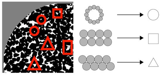
Figure 1. Schematic representation of cross-sectional pore and throat structures simplified based on porous media topology.
Early investigations of snap-off phenomena usually employed glass tubes with circular cross-sections as representative flow media [52][53][54][55][56]. Circular shapes, due to their relatively simple geometry, were convenient for construction. Additionally, the predictability and ease of modeling fluid flow through pores with circular cross-sections made them a popular choice in related studies. However, it is essential to acknowledge that such geometries may not fully capture the intricacies of irregularly shaped pores.
Noncircular cross-sections can have various effects on fluid flow and interface behavior compared to simple circular cross-sections, primarily due to factors like the corner effect and shape-dependent surface tension. Experimental observations have demonstrated that the snap-off process occurs more rapidly in channels with noncircular cross-sections when compared to circular cross-sections [57]. This outcome is attributed to reduced flow resistance within the noncircular channels, primarily due to the presence of corners. This corner effect, by reducing resistance, facilitates higher flow rates of the continuous wetting phase [57], thereby promoting the snap-off process.
Besides the corner effect, noncircular cross-sections can induce shape-dependent surface tension, which, in turn, affects the capillary pressure within porous media accommodating two-phase fluids due to the presence of more complex interfaces in such noncircular geometries. These interfaces comprise two distinct types: the main terminal meniscus (MTM) and arc menisci (AMs). The MTM, which divides wetting and nonwetting phases in the center of the pore and throat, represents the invading meniscus located at the pores and throats. It constitutes the primary curvature between the two phases and is present in both circular and noncircular cross-sectional geometries. In contrast, the AMs are interfaces that only exists in noncircular cross-sections, typically occurring at the corners of such geometries, and they are considered secondary curvatures [58]. The presence and characteristics of the AMs heavily depend on the specific angular geometry of the noncircular cross-section.
In the case of circular cross-sections, the principal radii of curvature (r1 and r2) represent the distances from the center of the circle to any point on the boundary along two perpendicular directions. In circular interfaces, all points on the boundary are equidistant from the center, making r1 = r2 = r, where r is the radius of the circular interface. Additionally, r can be further expressed as r = R/𝑐𝑜𝑠𝜃, where R represents the radius of the circular tube, σij signifies the interfacial tension, and θ denotes the contact angle. Therefore, Equation (1) can be simplified as shown in Equation (3),
In the case of noncircular cross-sections, the interface between the two-phase fluids becomes more complex. The curvature of the interface is assumed to be negligible in the plane perpendicular to that of the paper, which implies that the principal radii of curvature would be r1 = r and r2 = ∞ [58]. Under these circumstances, the capillary pressure across the interface can be simplified using Equation (4), where the specific value of r is closely related to the characteristics of the MTM and AMs in different noncircular cross-sections. In other words, the MTM and AMs exhibit distinct characteristics in various noncircular cross-sections, and the specific values of the capillary pressure for two-phase fluids in different noncircular cross-sections can be further calculated in detail using the MS-P theory [58][59][60] and the formulas introduced by Ma et al. for the curvature and radius variation calculations of the MTM and AMs [61].
The MS-P method is based on equating the pressure difference across the AMs at the capillary tube’s corners to that of the MTM [58]. In conjunction with a multiphase system at a constant temperature, the Helmholtz free energy (F) can be expressed as:
Here, for the bulk phase i and j, there are 𝑑𝐹𝑖=−𝑃𝑖𝑑𝑉𝑖, 𝑑𝐹𝑗=−𝑃𝑗𝑑𝑉𝑗, and 𝑑𝐹𝑖𝑛𝑡𝑒𝑟𝑓𝑎𝑐𝑒=−𝜎𝑖𝑗𝑑𝐴𝑖𝑗. Equation (5) can be further represented as Equation (6):
In a system with constant temperature and constant total volume, equilibrium is achieved when the Helmholtz free energy F reaches its minimum value, which is represented as
Combining Equations (6) and (7), for a noncircular cross-section containing two phases, water and oil, there is
By incorporating the geometric relationships [58] among water, oil, and the soil surface (Equation (9)) into Equation (8), the final expression for the capillary pressure in a noncircular cross-section [58] is derived as Equation (10),
where 𝜎𝑜𝑤 represents the interfacial tension between water and oil, 𝐿𝑛𝑜𝑤 is contact line between water and oil after displacement, 𝐿𝑛𝑜𝑠 is contact line between the oil and solid surface after displacement, 𝜃𝑜𝑤 denotes contact angle of water on the reservoir porous medium, and 𝐴𝑛𝑜 is the contact area of the oil on the solid surface.
Upon comparing Equations (3) and (10), it becomes evident that the determination of the capillary pressure involved in the two-phase fluids within porous media featuring circular cross-sections is relatively straightforward, requiring the interfacial tension, contact angle, and pore cross-section radius. However, in porous media characterized with angular cross-sectional structures, determining the capillary pressure becomes notably intricate. It involves considerations of the interfacial tension, contact angle, and contact status of water–oil–solid surface (encompassing the water–oil contact line, oil–solid surface contact line, and oil–solid surface contact area). Notably, irrespective of whether the pore geometry features a circular or noncircular cross-section, the capillary pressure exhibits a dependence on the contact angle, which is dictated by wettability. This observation signifies that changes in the wettability can induce alterations in the capillary pressure within any pore geometry.
3.3.2. Pore–Throat Connection
Porous media fundamentally consist of network systems composed of relatively larger-volume pores interconnected by smaller-volume throats or constrictions. This structural connectivity not only delineates porous media but also significantly influences fluid flow phenomena within them, particularly in multiphase flow scenarios.
In the context of pore–throat systems, the occurrence of snap-off phenomena is influenced by the geometric configuration of the pore–throat, specifically the ratio of the throat length to the pore diameter, abbreviated as the length-to-diameter ratio. Yao et al. conducted experiments using microfluidic pore–throat systems in which they systematically varied the length-to-diameter ratio during oil–water imbibition experiments to analyze the impact of pore–throat connections on snap-off phenomena [12][34][49][62]. The experimental results demonstrated that, under different length-to-diameter ratios, distinct displacement behaviors occurred, as depicted in Figure 2.
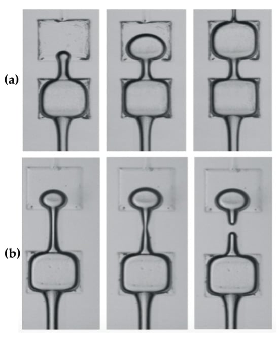
Figure 2. Two-phase flow behaviors within pore–throat connections with different length-to-diameter ratios. (a) Piston-like displacement at the length-to-diameter ratio of 2.22. (b) Snap-off at the length-to-diameter ratio of 3.44.
After confirming the possibility of snap-off occurrence through the Rayleigh–Plateau instability theory, the volume and position of the resulting snap-off bubble or droplet can be determined based on the aspect ratio, which is defined as the ratio of the throat length to the throat width [34]. Regarding the volume of the snap-off droplet, when the throat width remains constant, the volume decreases as the aspect ratio increases. In terms of the location where the snap-off droplet forms, when the aspect ratio exceeds 1, the resulting droplet forms within the throat. Conversely, when the aspect ratio is less than 0.75, the snap-off droplet forms in the wider pore region after passing through the throat. When the aspect ratio falls within the range of 0.75 to 1, both of these scenarios may occur [34]. Compared to larger droplets formed in narrow structures, smaller droplets or those formed in wider pore locations exhibit improved flow characteristics.
4. Impacts of Snap-Off
4.1. Unrecoverable Oil Droplet Formation
Unrecoverable oil droplets represent a direct outcome of the snap-off phenomenon, and they play a pivotal role in shaping the microscopic distribution of the remaining oil within porous media in reservoirs [54][63]. In the context of reservoir exploitation, waterflooding stands as a prevalent method. During waterflooding operations, the nonwetting phase, typically crude oil, undergoes displacement by the wetting phase, which is water. Within this process, snap-off events may transpire. To elaborate, when crude oil is displaced to the central region of pore throats and gradually dislodged from the pore walls by the advancing wetting phase, snap-off occurrences lead to the formation of oil droplets. These oil droplets become entrapped within the pores, rendering them immobile and resistant to further displacement, hence the designation unrecoverable oil droplets. The impact of these unrecoverable oil droplets on crude oil production is substantial [64].
4.2. Oil Bridging Effect
The oil bridging effect [54][65] represents a significant potential outcome of snap-off phenomena, particularly noteworthy in heterogeneous reservoirs characterized by a diverse range of pore sizes and geometries. This effect arises from the intricate interplay between snap-off events and the inherent properties of such heterogeneous porous media. It results in the entrapment of nonwetting-phase droplets within pore throats, giving rise to bridging-like structures or obstructions [66][67], rather than spherical shapes.
In these heterogeneous oil reservoirs, significant disparities exist in the dimensions of pores and throats, manifesting substantial differences in their interactions with fluids. Larger pores, characterized by their expansive cross-sectional areas and lower hydraulic resistance, tend to facilitate fluid flow, resulting in heightened fluid–pore interactions and consequential alterations in surface properties, particularly wettability. Conversely, smaller throats, characterized by their reduced cross-sectional areas and higher hydraulic resistance, impede fluid flow, maintaining their inherent wettability with limited fluid interactions. In instances where larger pores with significantly modified wettability are interconnected with smaller throats exhibiting unaltered wettability, forming integrated pore–throat systems, the formation of snap-off-induced droplets leads to distinct interfacial tension at interfaces near pore surfaces and those adjacent to throat surfaces. This variance in interfacial tensions results in droplet deformation, ultimately culminating in the formation of bridge-like structures.
4.3. Drainage–Imbibition Hysteresis
Snap-off serves as the fundamental cause of drainage–imbibition hysteresis [56][68][69], a phenomenon characterized by distinct variations in flow dynamics during drainage (the expulsion of liquid from pores) and imbibition (the infiltration of liquid into pores) processes within porous media.
This hysteresis can significantly influence fluid behaviors and flow mechanisms in such media, most notably evident in the nonalignment of relative permeability curves for the wetting phase during drainage and imbibition processes [32][70]. During drainage, the relative permeability of the wetting phase is higher, indicating relatively easier pore occupancy. However, in the imbibition process, particularly in porous media with nonuniform pore structure or microscale heterogeneity [71], the relative permeability of the wetting phase decreases, indicating the challenges for the wetting phase in completely occupying the pore space.
4.4. Strong Foam Generation
Foam generation is essentially synonymous with gas bubble generation [72]. Consequently, the production of foam within porous media is closely intertwined with snap-off phenomena. Foam generation denotes the occurrence wherein gas bubbles form within the porous medium during the multiphase flow, with the wetting phase and nonwetting phase within the porous medium assuming the roles of liquid and gas phases, respectively. Previous studies on the mechanism of gas bubble formation have identified snap-off as one primary principal mechanism responsible for the generation of strong foam [73][74][75].
During multiphase fluid flow, foam generation can be classified into different categories, including strong foam and weak foam. Strong foam is the term used to describe relatively large and stable gas bubbles that are produced when the wetting phase rapidly pinches off the nonwetting phase. In contrast, weak foam consists of smaller and less stable bubbles. In porous media where gas and liquid coexist, gas, acting as the nonwetting phase, undergoes separation from the wetting liquid phase through snap-off phenomena, leading to the formation of larger gas bubbles.
4.5. Transient/Dynamic Effects
Apart from the aforementioned microscale consequences, snap-off can also exert an influence on specific macroscopic or continuum-scale parameters within the realm of porous media and multiphase flow. These effects are categorized as transient/dynamic effects, which are typically more pronounced in porous media characterized by coarser textures [76][77].
Droplets and bubbles, generated through snap-off, have been proven to influence fluid redistribution and introduce macroscale inhomogeneities at transient state [76][78]. When snap-off events occur, the entrapment of oil droplets or gas bubbles occupies a portion of the pore volume within the porous medium. Consequently, this augments the relative proportion of the nonwater phase in the reservoir, leading to a reduction in water saturation. It is essential to note that water saturation maintains a well-established constitutive relationship with relative permeability [76]. During multiphase flow, the decline in water saturation typically coincides with a decrease in the water relative permeability. This decrease implies greater challenges in displacing oil or gas by water, ultimately resulting in a reduced oil-recovery rate.
4.6. Interconnections between Effects
The various effects induced by snap-off, as previously elucidated, are not isolated but rather interconnected. The most conspicuous and common effect of snap-off is the formation of unrecoverable oil droplets. When these unrecoverable oil droplets occur within heterogeneous oil reservoirs characterized by a wide range of pore sizes and geometries, factors such as disparities in the interfacial tension, local pressure, and saturation, resulting from significant variations in pore and throat dimensions, lead to the deformation of trapped oil droplets, transforming them from spheres into bridge-like shapes and giving rise to the oil bridging effect.
Whether in the form of spherical trapped oil droplets or deformed oil bridges, these entities, serving as obstacles within the porous medium, can alter fluid distribution at the microscopic level. Consequently, this alteration initiates drainage–imbibition hysteresis and transient/dynamic effects, leading to a reduction in key macroscopic parameters, such as water saturation within the porous medium and water relative permeability in the context of two-phase flow. This reduction has a significant adverse impact on oil- or gas-recovery processes.
5. Prevention and Utilization of Snap-Off
5.1. Prevention of Snap-Off in Waterflooding for Oil Production
During the crude oil production through waterflooding, the occurrence of snap-off typically exerts a detrimental influence on crude oil-recovery rates. This adverse impact arises from the interaction of oil and water phases during the waterflooding process, where the oil phase frequently undergoes snap-off events [49][66]. Consequently, this leads to the formation of unrecoverable oil droplets, some of which may become entrapped in the narrow constrictions of the reservoir’s porous media. These trapped oil droplets pose significant challenges to effective displacement, rendering them irrecoverable residual oil droplets. Furthermore, the subsequent oil bridging effect, induced by the presence of these residual oil droplets resulting from snap-off, further obstructs the unimpeded flow of the displacing phase within the porous media. This additional hindrance substantially diminishes crude oil-recovery rates.
Essentially, during the waterflooding process, the formation of unrecoverable oil droplets, the oil bridging effect, and drainage–imbibition hysteresis caused by the snap-off phenomenon collectively contribute to an increased volume of trapped oil within subterranean reservoirs. This trapped oil becomes inaccessible, ultimately leading to lower oil recovery. Therefore, extensive research and technological advancements within the petroleum industry are directed towards mitigating or preventing the snap-off phenomenon to enhance recovery rates [79][80].
5.2. Utilization of Snap-Off in CO2-EOR
CO2-EOR, also referred to as CO2 flooding, is a reservoir engineering technique employed to enhance oil recovery using CO2 [81][82][83]. Typically, it finds application in reservoirs where conventional waterflooding has been conducted, yet a substantial quantity of crude oil remains within the porous media of reservoirs. The fundamental principle underlying CO2-EOR involves the injection of CO2 into the reservoir, primarily to reduce the viscosity of crude oil by blending with it within the interstitial spaces of the porous medium. This process plays a pivotal role in enhancing the flowability of crude oil, consequently elevating the sweep efficiency, and thereby increasing both the oil-production efficiency and oil-recovery rate. Furthermore, during the implementation of CO2-EOR, the introduction of appropriate foaming agents alongside CO2 can lead to interactions with reservoir fluids that induce the occurrence of snap-off phenomena [84]. This phenomenon results in the formation of gas bubbles within the oil phase, which are effectively stabilized by the foaming agents.
5.3. Utilization of Snap-Off in CO2 Storage
During the process of CO2 geological storage, the occurrence of the snap-off phenomenon significantly enhances storage efficiency [81]. The characteristics of CO2 storage in saline aquifers share similarities with oil production through waterflooding in oil reservoirs, both involving immiscible two-phase fluids within porous media. Typically, brine or water serves as the wetting phase, while CO2 gas or oil function as the nonwetting phase. Therefore, findings related to snap-off in oil reservoirs can contribute to a deeper understanding of the theoretical aspects and mechanisms behind CO2 storage in saline aquifers.
In summary, CO2 geological storage in saline aquifers leverages the strong foam generation effect of snap-off to promote the formation of large, stable CO2 bubbles. Subsequently, transient/dynamic effects induced by snap-off lead to a reduction in water saturation. As a consequence, water relative permeability decreases, impeding water flow within the porous medium, thereby facilitating the primary goal of stably storing CO2 bubbles within saline aquifer porous media. To optimize the efficient application of snap-off for CO2 geological storage, several technical measures should be considered. It is necessary to evaluate the storage capacity and sealing properties of the selected saline aquifers. The CO2 injection flow rate and pressure should be controlled within manageable ranges. Additionally, the implementation of numerical simulations before CO2 injection, real-time monitoring during injection, and long-term poststorage monitoring are essential components of this process.
References
- Morrow, N.R.; Mason, G. Recovery of Oil by Spontaneous Imbibition. Curr. Opin. Colloid Interface Sci. 2001, 6, 321–337.
- Zhou, X.; Torsæter, O.; Xie, X.; Morrow, N.R. The Effect of Crude-Oil Aging Time and Temperature on the Rate of Water Imbibition and Long-Term Recovery by Imbibition. SPE Form. Eval. 1995, 10, 259–265.
- Babadagli, T. Temperature Effect on Heavy-Oil Recovery by Imbibition in Fractured Reservoirs. J. Pet. Sci. Eng. 1996, 14, 197–208.
- Wang, X.; Peng, X.; Zhang, S.; Du, Z.; Zeng, F. Characteristics of Oil Distributions in Forced and Spontaneous Imbibition of Tight Oil Reservoir. Fuel 2018, 224, 280–288.
- Clarkson, C.; Yuan, B.; Zhang, Z.; Tabasinejad, F.; Behmanesh, H.; Hamdi, H.; Anderson, D.; Thompson, J.; Lougheed, D. Anomalous Diffusion or Classical Diffusion in an Anomalous Reservoir? Evaluation of the Impact of Multi-Phase Flow on Reservoir Signatures in Unconventional Reservoirs. In Proceedings of the 7th Unconventional Resources Technology Conference, Denver, CO, USA, 22–24 July 2019.
- Lin, D.; Wang, J.; Yuan, B.; Shen, Y. Review on Gas Flow and Recovery in Unconventional Porous Rocks. Adv. Geo-Energy Res. 2017, 1, 39–53.
- Zhu, D.; Li, B.; Zheng, L.; Lei, W.; Li, B.; Li, Z. Effects of CO2 and Surfactants on the Interface Characteristics and Imbibition Process in Low-Permeability Heavy Oil Reservoirs. Colloids Surf. A Physicochem. Eng. Asp. 2023, 657, 130538.
- Yao, J.; Li, G.; Wu, J. Application of In-Situ Combustion for Heavy Oil Production in China: A Review. J. Oil Gas Petrochem. Sci. 2018, 1, 69–72.
- Yao, J.; Song, Y. Dynamic Analysis Approach to Evaluate In-Situ Combustion Performance for Heavy Oil Production. J. Oil Gas Petrochem. Sci. 2019, 2, 42–47.
- Aghaeifar, Z.; Strand, S.; Puntervold, T. Significance of Capillary Forces during Low-Rate Waterflooding. Energy Fuels 2019, 33, 3989–3997.
- Li, J.; McDougall, S.R.; Sorbie, K.S. Dynamic Pore-Scale Network Model (PNM) of Water Imbibition in Porous Media. Adv. Water Resour. 2017, 107, 191–211.
- Yao, J. A Microfluidic Model for Visualizing Snap-off During Imbibition. Ph.D. Dissertation, University of Wyoming, Laramie, WY, USA, 2017.
- Andersen, P.Ø.; Salomonsen, L.; Sleveland, D.S. Characteristic Forced and Spontaneous Imbibition Behavior in Strongly Water-Wet Sandstones Based on Experiments and Simulation. Energies 2022, 15, 3531.
- Liu, Y.; Berg, S.; Ju, Y.; Wei, W.; Kou, J.; Cai, J. Systematic Investigation of Corner Flow Impact in Forced Imbibition. Water Resour. Res. 2022, 58, e2022WR032402.
- Nguyen, V.H.; Sheppard, A.P.; Knackstedt, M.A.; Pinczewski, W.V. A Dynamic Network Model for Imbibition. In Proceedings of the SPE Annual Technical Conference and Exhibition, Houston, TX, USA, 26–29 September 2004.
- Prodanović, M.; Bryant, S.L. A Level Set Method for Determining Critical Curvatures for Drainage and Imbibition. J. Colloid Interface Sci. 2006, 304, 442–458.
- Meng, Q.; Liu, H.; Wang, J. Entrapment of the Non-Wetting Phase during Co-Current Spontaneous Imbibition. Energy Fuels 2015, 29, 686–694.
- Cai, J.; Yu, B.; Zou, M.; Luo, L. Fractal Characterization of Spontaneous Co-Current Imbibition in Porous Media. Energy Fuels 2010, 24, 1860–1867.
- Takahashi, S.; Kovscek, A.R. Spontaneous Countercurrent Imbibition and Forced Displacement Characteristics of Low-Permeability, Siliceous Shale Rocks. J. Pet. Sci. Eng. 2010, 71, 47–55.
- Kashchiev, D.; Firoozabadi, A. Analytical Solutions for 1D Countercurrent Imbibition in Water-Wet Media. SPE J. 2003, 8, 401–408.
- Pooladi-Darvish, M.; Firoozabadi, A. Cocurrent and Countercurrent Imbibition in a Water-Wet Matrix Block. SPE J. 2000, 5, 3–11.
- Tanino, Y.; Zacarias-Hernandez, X.; Christensen, M. Oil/Water Displacement in Microfluidic Packed Beds under Weakly Water-Wetting Conditions: Competition between Precursor Film Flow and Piston-like Displacement. Exp. Fluids 2018, 59, 35.
- Rezaei Dehshibi, R.; Sadatshojaie, A.; Mohebbi, A.; Riazi, M. A New Insight into Pore Body Filling Mechanism during Waterflooding in a Glass Micro-Model. Chem. Eng. Res. Des. 2019, 151, 100–107.
- Roof, J.G. Snap-Off of Oil Droplets in Water-Wet Pores. Soc. Pet. Eng. J. 1970, 10, 85–90.
- Falls, A.H.; Hirasaki, G.J.; Patzek, T.W.; Gauglitz, D.A.; Miller, D.D.; Ratulowski, T. Development of a Mechanistic Foam Simulator: The Population Balance and Generation by Snap-Off. SPE Reserv. Eng. 1988, 3, 884–892.
- Gauglitz, P.A.; Laurent, C.M.S.; Radke, C.J. Experimental Determination of Gas-Bubble Breakup in a Constricted Cylindrical Capillary. Ind. Eng. Chem. Res. 1988, 27, 1282–1291.
- Goldsmith, H.L.; Mason, S.G. The Movement of Single Large Bubbles in Closed Vertical Tubes. J. Fluid Mech. 1962, 14, 42–58.
- Mast, R.F. Microscopic Behavior of Foam in Porous Media. In Proceedings of the Fall Meeting of the Society of Petroleum Engineers of AIME, San Antonio, TX, USA, 8–11 October 1972.
- Ransohoff, T.C.; Radke, C.J. Laminar Flow of a Wetting Liquid along the Corners of a Predominantly Gas-Occupied Noncircular Pore. J. Colloid Interface Sci. 1988, 121, 392–401.
- Aghaei, A.; Piri, M. Direct Pore-to-Core up-Scaling of Displacement Processes: Dynamic Pore Network Modeling and Experimentation. J. Hydrol. 2015, 522, 488–509.
- Zankoor, A.; Khishvand, M.; Mohamed, A.; Wang, R.; Piri, M. In-Situ Capillary Pressure and Wettability in Natural Porous Media: Multi-Scale Experimentation and Automated Characterization Using X-Ray Images. J. Colloid Interface Sci. 2021, 603, 356–369.
- Fulcher, R.A.; Ertekin, T.; Stahl, C.D. Effect of Capillary Number and Its Constituents on Two-Phase Relative Permeability Curves. J. Pet. Technol. 1985, 37, 249–260.
- Guo, H.; Dou, M.; Hanqing, W.; Wang, F.; Yuanyuan, G.; Yu, Z.; Yansheng, W.; Li, Y. Proper Use of Capillary Number in Chemical Flooding. J. Chem. 2017, 2017, 4307368.
- Olbricht, W.L. Pore-Scale Prototypes of Multiphase Flow in Porous Media. Annu. Rev. Fluid. Mech. 1996, 28, 187–213.
- Yao, J.; Oakey, J. Geometrically-Mediated Snap-off of Water-in-Oil Emulsion Droplets in Microfluidic Flow Focusing Devices. J. Oil Gas Petrochem. Sci. 2018, 1, 42–46.
- Li, Z.; Gu, Z.; Li, R.; Wang, C.; Chen, C.; Yu, C.; Zhang, Y.; Shu, Q.; Su, J. Investigation on Droplet Dynamic Snap-off Process in a Short, Abrupt Constriction. Chem. Eng. Sci. 2021, 235, 116496.
- Peña, T.J.; Carvalho, M.S.; Alvarado, V. Snap-off of a Liquid Drop Immersed in Another Liquid Flowing through a Constricted Capillary. AIChE J. 2009, 55, 1993–1999.
- Tsai, T.M.; Miksis, M.J. Dynamics of a Drop in a Constricted Capillary Tube. J. Fluid Mech. 1994, 274, 197–217.
- Yao, J. Microfluidic Studies on Snap-Off during Imbibition Process. Master’s Thesis, China University of Petroleum (East China), Qingdao, China, 2014.
- Herring, A.L.; Gilby, F.J.; Li, Z.; McClure, J.E.; Turner, M.; Veldkamp, J.P.; Beeching, L.; Sheppard, A.P. Observations of Nonwetting Phase Snap-off during Drainage. Adv. Water Resour. 2018, 121, 32–43.
- Bai, X.; Yan, G.; Kong, S.; Yang, T.; Yao, J.; Wen, P.; Li, G. Study on the Mechanism of the Influence of Surfactant Alkyl Chain Length on the Wettability of Anthracite Dust Based on EDLVO Theory and Inverse Gas Chromatography. Fuel 2023, 353, 129187.
- Bai, X.; Yan, G.; Kong, S.; Yao, J.; Wen, P.; Li, G.; Li, J.; Zhang, J. Suppression of Anthracite Dust by a Composite of Oppositely-Charged Ionic Surfactants with Ultra-High Surface Activity: Theoretical Calculation and Experiments. Fuel 2023, 344, 128075.
- Amirmoshiri, M.; Zhang, L.; Puerto, M.C.; Tewari, R.D.; Bahrim, R.Z.B.K.; Farajzadeh, R.; Hirasaki, G.J.; Biswal, S.L. Role of Wettability on the Adsorption of an Anionic Surfactant on Sandstone Cores. Langmuir 2020, 36, 10725–10738.
- Amott, E. Observations Relating to the Wettability of Porous Rock. Trans. AIME 1959, 216, 156–162.
- Wardlaw, N.C. The Effects of Geometry, Wettability, Viscosity And Interfacial Tension On Trapping In Single Pore-Throat Pairs. J. Can. Pet. Technol. 1982, 21, PETSOC-82-03-01.
- Yu, L.; Wardlaw, N.C. The Influence of Wettability and Critical Pore-Throat Size Ratio on Snap—Off. J. Colloid Interface Sci. 1986, 109, 461–472.
- Al-Futaisi, A.; Patzek, T.W. Impact of Wettability Alteration on Two-Phase Flow Characteristics of Sandstones: A Quasi-Static Description. Water Resour. Res. 2003, 39, 1042.
- Stratford, K.; Adhikari, R.; Pagonabarraga, I.; Desplat, J.-C.; Cates, M.E. Colloidal Jamming at Interfaces: A Route to Fluid-Bicontinuous Gels. Science (1979) 2005, 309, 2198–2201.
- Melle, S.; Lask, M.; Fuller, G.G. Pickering Emulsions with Controllable Stability. Langmuir 2005, 21, 2158–2162.
- Yao, J. Microfluidic Studies of Geometrically-Mediated Snap-Off. Master’s Thesis, University of Wyoming, Laramie, WY, USA, 2014.
- Sulerud, T.; Sami, A.B.; Li, G.; Kloxin, A.; Oakey, J.; Gatlin, J. Microtubule-Dependent Pushing Forces Contribute to Long-Distance Aster Movement and Centration in Xenopus Laevis Egg Extracts. Mol. Biol. Cell 2020, 31, 2791–2802.
- Li, G. 3D Printed Microfluidic Devices for Controlled Biomaterial Fabrication. Ph.D. Dissertation, University of Wyoming, Laramie, WY, USA, 2020.
- Chen, J.D. Measuring the Film Thickness Surrounding a Bubble inside a Capillary. J. Colloid Interface Sci. 1986, 109, 341–349.
- Gauglitz, P.A.; Radke, C.J. The Dynamics of Liquid Film Breakup in Constricted Cylindrical Capillaries. J. Colloid Interface Sci. 1990, 134, 14–40.
- Chatzis, I.; Morrow, N.R.; Lim, H.T. Magnitude and Detailed Structure of Residual Oil Saturation. Soc. Pet. Eng. J. 1983, 23, 311–326.
- Westborg, H.; Hassager, O. Creeping Motion of Long Bubbles and Drops in Capillary Tubes. J. Colloid Interface Sci. 1989, 133, 135–147.
- Yu, L.; Wardlaw, N.C. Mechanisms of Nonwetting Phase Trapping during Imbibition at Slow Rates. J. Colloid Interface Sci. 1986, 109, 473–486.
- Arriola, A.; Willhite, G.P.; Green, D.W. Trapping of Oil Drops in a Noncircular Pore Throat and Mobilization Upon Contact With a Surfactant. Soc. Pet. Eng. J. 1983, 23, 99–114.
- Mohammad Piri Pore-Scale Modeling of Three-Phase Flow. Ph.D. Dissertation, Imperial College London, London, UK, 2003.
- Sedghi, M.; Piri, M.; Goual, L. Molecular Dynamics of Wetting Layer Formation and Forced Water Invasion in Angular Nanopores with Mixed Wettability. J. Chem. Phys. 2014, 141, 194703.
- Anbari, A.; Lowry, E.; Piri, M. Estimation of Capillary Pressure in Unconventional Reservoirs Using Thermodynamic Analysis of Pore Images. J. Geophys. Res. Solid Earth 2019, 124, 10893–10915.
- Ma, S.; Mason, G.; Morrow, N.R. Effect of Contact Angle on Drainage and Imbibition in Regular Polygonal Tubes. Colloids Surf. A Physicochem. Eng. Asp. 1996, 117, 273–291.
- Qu, Z.; Yao, J.; Yang, Y.; Wang, B.; He, L. Laboratory Experiments of a Microfluidic Model for Imbibition. J. Petrochem. Univ. 2014, 37, 64–66.
- Chatzis, I.; Dullien, F.A.L. Dynamic Immiscible Displacement Mechanisms in Pore Doublets: Theory versus Experiment. J. Colloid Interface Sci. 1983, 91, 199–222.
- Larson, R.G. The Influence of Phase Behavior on Surfactant Flooding. Soc. Pet. Eng. J. 1979, 19, 411–422.
- Nayberg, T.M. Laboratory Study of Lost Circulation Materials for Use in both Oil-Based and Water-Based Drilling Muds. SPE Drill. Eng. 1987, 2, 229–236.
- Morrow, N.R. Wettability and Its Effect on Oil Recovery. J. Pet. Technol. 1990, 42, 1476–1484.
- Dickinson, E.; Flint, F.O.; Hunt, J.A. Bridging Flocculation in Binary Protein Stabilized Emulsions. Food Hydrocoll. 1989, 3, 389–397.
- Delshad, M.; Pope, G.A. Comparison of the Three-Phase Oil Relative Permeability Models. Transp. Porous Media 1989, 4, 59–83.
- Fayers, F.J.; Matthews, J.D. Evaluation of Normalized Stone’s Methods for Estimating Three-Phase Relative Permeabilities. Soc. Pet. Eng. J. 1984, 24, 224–232.
- Jerauld, G.R.; Salter, S.J. The Effect of Pore-Structure on Hysteresis in Relative Permeability and Capillary Pressure: Pore-Level Modeling. Transp. Porous Media 1990, 5, 103–151.
- Lenormand, R.; Zarcone, C.; Sarr, A. Mechanisms of the Displacement of One Fluid by Another in a Network of Capillary Ducts. J. Fluid Mech. 1983, 135, 337.
- Almajid, M.M.; Kovscek, A.R. Pore-Level Mechanics of Foam Generation and Coalescence in the Presence of Oil. Adv. Colloid Interface Sci. 2016, 233, 65–82.
- Kovscek, A.R.; Radke, C.J. Pressure-Driven Capillary Snap-off of Gas Bubbles at Low Wetting-Liquid Content. Colloids Surf. A Physicochem. Eng. Asp. 2003, 212, 99–108.
- Almajid, M.M.; Kovscek, A.R. Pore Network Investigation of Trapped Gas and Foam Generation Mechanisms. Transp. Porous Media 2020, 131, 289–313.
- Ransohoff, T.C.; Radke, C.J. Mechanisms of Foam Generation in Glass-Bead Packs. SPE Reserv. Eng. 1988, 3, 573–585.
- Yan, G.; Li, Z.; Galindo Torres, S.A.; Scheuermann, A.; Li, L. Transient Two-Phase Flow in Porous Media: A Literature Review and Engineering Application in Geotechnics. Geotechnics 2022, 2, 32–90.
- Hassanizadeh, S.M.; Celia, M.A.; Dahle, H.K. Dynamic Effect in the Capillary Pressure-Saturation Relationship and Its Impacts on Unsaturated Flow. Vadose Zone J. 2002, 1, 38–57.
- Malaya, C.; Sreedeep, S. Critical Review on the Parameters Influencing Soil-Water Characteristic Curve. J. Irrig. Drain. Eng. 2012, 138, 55–62.
- Shams, M.; Singh, K.; Bijeljic, B.; Blunt, M.J. Direct Numerical Simulation of Pore-Scale Trapping Events During Capillary-Dominated Two-Phase Flow in Porous Media. Transp. Porous Media 2021, 138, 443–458.
- Barkley, S.; Scarfe, S.J.; Weeks, E.R.; Dalnoki-Veress, K. Predicting the Size of Droplets Produced through Laplace Pressure Induced Snap-Off. Soft Matter 2016, 12, 7398–7404.
- Yao, J.; Han, H.; Yang, Y.; Song, Y.; Li, G. A Review of Recent Progress of Carbon Capture, Utilization, and Storage (CCUS) in China. Appl. Sci. 2023, 13, 1169.
- Liu, Y.; Rui, Z. A Storage-Driven CO2 EOR for a Net-Zero Emission Target. Engineering 2022, 18, 79–87.
- Li, G.; Yao, J.; Song, Y.; Tang, J.; Han, H.; Cui, X. A Review of the Metallogenic Mechanisms of Sandstone-Type Uranium Deposits in Hydrocarbon-Bearing Basins in China. Eng 2023, 4, 1723–1741.
-
P c = P i − P j = σ i j ( 1 r 1 + 1 r 2 ) - Morrow, N.R.; Mason, G. Recovery of Oil by Spontaneous Imbibition. Curr. Opin. Colloid Interface Sci. 2001, 6, 321–337.
More
Information
Subjects:
Engineering, Petroleum
Contributors
MDPI registered users' name will be linked to their SciProfiles pages. To register with us, please refer to https://encyclopedia.pub/register
:
View Times:
1.6K
Revisions:
2 times
(View History)
Update Date:
27 Nov 2023
Table of Contents


Notice
You are not a member of the advisory board for this topic. If you want to update advisory board member profile, please contact office@encyclopedia.pub.
OK
Confirm
Only members of the Encyclopedia advisory board for this topic are allowed to note entries. Would you like to become an advisory board member of the Encyclopedia?
Yes
No
${ textCharacter }/${ maxCharacter }
Submit
Cancel
Back
Comments
${ item }
|
${ item.createdUser.fullName }
${ item.createdAt }
${ item.vote }
${ item.reply }
Delete
${ reply.createdUser.fullName }
${ reply.createdAt }
${ reply.vote }
Delete
There is no reply to this comment~
${ item.replyTextCharacter }/${ item.replyMaxCharacter }
Submit
Cancel
More
No more~
There is no comment~
${ textCharacter }/${ maxCharacter }
Submit
Cancel
${ selectedItem.replyTextCharacter }/${ selectedItem.replyMaxCharacter }
Submit
Cancel
Confirm
Are you sure to Delete?
Yes
No