Your browser does not fully support modern features. Please upgrade for a smoother experience.
Submitted Successfully!
 +1 credit
Thank you for your contribution! You can also upload a video entry or images related to this topic.
For video creation, please contact our Academic Video Service.
| Version | Summary | Created by | Modification | Content Size | Created at | Operation |
|---|---|---|---|---|---|---|
| 1 | Lisha Peng | -- | 1176 | 2023-11-16 07:56:59 | | | |
| 2 | Jessie Wu | Meta information modification | 1176 | 2023-11-17 02:06:32 | | | | |
| 3 | Jessie Wu | Meta information modification | 1176 | 2023-11-17 02:07:50 | | |
Video Upload Options
We provide professional Academic Video Service to translate complex research into visually appealing presentations. Would you like to try it?
Cite
If you have any further questions, please contact Encyclopedia Editorial Office.
Huang, S.; Peng, L.; Sun, H.; Li, S. Magnetic Flux Leakage Testing Technique of Oil Pipelines. Encyclopedia. Available online: https://encyclopedia.pub/entry/51648 (accessed on 27 June 2026).
Huang S, Peng L, Sun H, Li S. Magnetic Flux Leakage Testing Technique of Oil Pipelines. Encyclopedia. Available at: https://encyclopedia.pub/entry/51648. Accessed June 27, 2026.
Huang, Songling, Lisha Peng, Hongyu Sun, Shisong Li. "Magnetic Flux Leakage Testing Technique of Oil Pipelines" Encyclopedia, https://encyclopedia.pub/entry/51648 (accessed June 27, 2026).
Huang, S., Peng, L., Sun, H., & Li, S. (2023, November 16). Magnetic Flux Leakage Testing Technique of Oil Pipelines. In Encyclopedia. https://encyclopedia.pub/entry/51648
Huang, Songling, et al. "Magnetic Flux Leakage Testing Technique of Oil Pipelines." Encyclopedia. Web. 16 November, 2023.
Copy Citation
Magnetic flux leakage testing (MFL) is the most widely used nondestructive testing technology in the safety inspection of oil and gas pipelines.
oil and gas pipeline
magnetic flux leakage
object detection
CNN
data
1. Introduction
Pipelines are the most commonly used facilities for transporting oil and gas resources over long distances. Given the rapid increases in the service age, geological changes, medium erosion, man-made damage, and other factors, the problem of oil and gas pipeline failures has attracted extensive attention globally. Regular detection and evaluation are effective means to ensure the integrity and reliability of oil and gas pipelines. There are many defect detection techniques, such as the electromagnetic ultrasonic guided wave (EUGW) test [1][2], the magnetic flux leakage (MFL) test [3][4], the eddy current (EC) [5][6] test, microwave detection [7][8], and acoustic emission (AE) detection [9][10]. Among these, the MFL testing technique is one of the most widely used pipeline detection methods owing to its advantages, such as high reliability, low requirements on the detection environment without a couplant, a good detection effect on high-permeability pipe defects, etc.
2. Basic Principles of Magnetic Flux Leakage Testing
Magnetic flux leakage (MFL) testing is an effective technique to detect the anomalies of oil and gas pipelines. In MFL testing, the ferromagnetic pipe wall is saturated magnetization by an external magnetic field. Magnetic sensors are placed near the surface of the pipe wall to detect the MFL signals. The magnetic field forms a closed loop through the magnet, magnetic yoke, and pipe wall. Due to the change of pipe wall thickness near defects or other anomalies, magnetic field lines will be distorted under the saturated magnetization state of the pipeline. As a result, partial magnetic field lines will leak from the pipe wall, which forms magnetic flux leakage. The magnetic sensors are then used to detect the MFL signal so as to conduct qualitative and quantitative analysis of the pipeline. Figure 1 shows the basic schematic diagram of pipeline MFL testing.
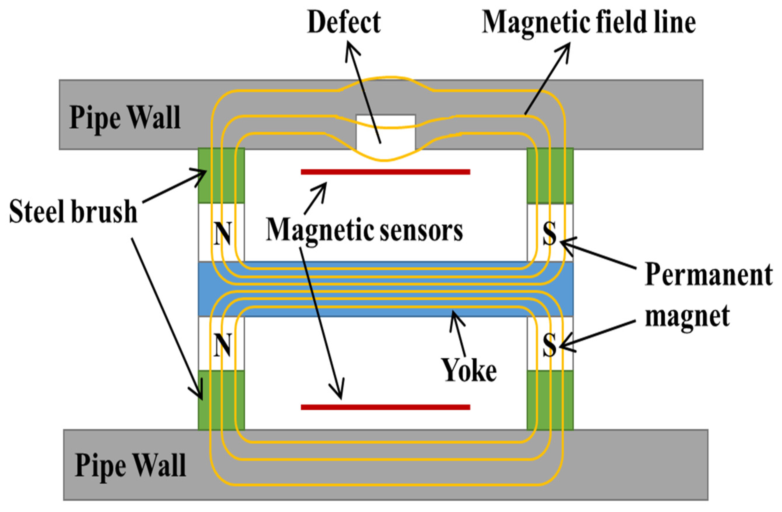
Figure 1. Basic schematic diagram of pipeline MFL testing.
3. Main Anomalies of Oil and Gas Pipelines
The pipe anomalies can usually be divided into three categories: defects, welds, and special components. Due to the morphological difference between these pipe anomalies and the pipe wall, MFL signals will be generated near them. It is meaningful to know about these anomalies for MFL analysis.
- (1)
-
Defects
Pipeline defects mainly include metal loss, corrosion, sag, weld defect, etc. Figure 2 shows these defects of pipeline. Among them, the metal loss is a common kind of defect in the pipeline. It contains metal scratches, pits, and so on, mainly due to man-made damage. The corrosion occurs due to outside environmental erosion (air or soil) and inside medium erosion (oil or gas). The increase in corrosion area will pose a severe threat to the pipeline’s safe operation. The sag is the cross-section change caused by permanent plastic deformation of the pipeline, which generally occurs during the excavation of pipeline construction. The weld defect is caused by the incompleteness of welded joints, mainly containing welding cracks, incomplete welding, slag inclusion, pores, etc. Weld defects tend to cause pipe-welding fractures.
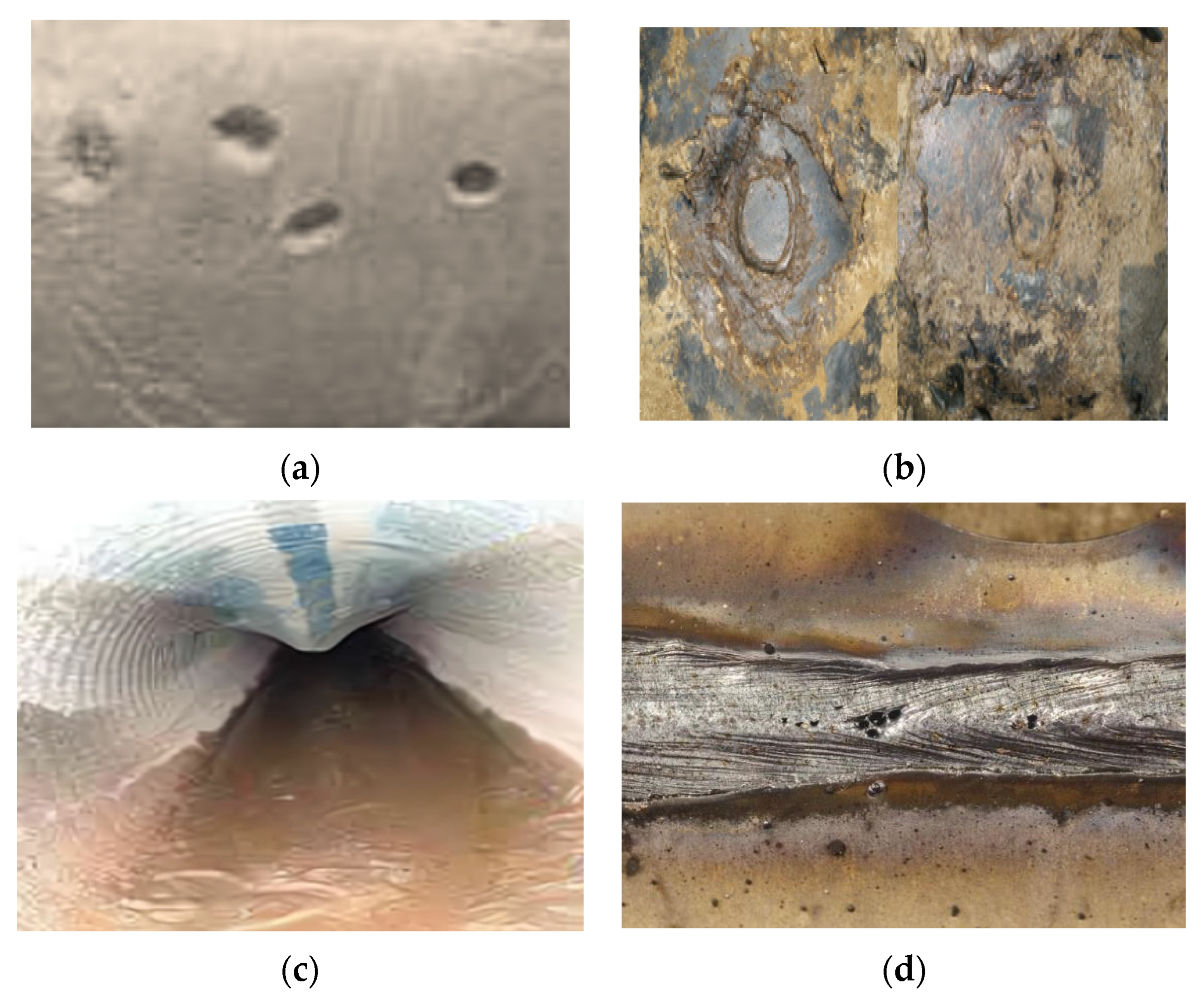
Figure 2. Defects of a pipeline. (a) metal loss; (b) corrosion; (c) sag; (d) weld defect.
- (2)
-
Welds
Welds are the most important anomalies of the long-distance oil and gas pipelines, which are used to connect the pipe segments. Pipeline welds commonly include girth, spiral, and straight welds. Figure 3 shows these welds of pipeline. Among them, the girth weld is formed by connecting straight pipes through welding technology. The spiral welds and straight welds are produced by the spiral or straight welding process of steel plates or strips, respectively. Since the material at the weld is quite different from the pipe, and the wall thickness at the welding is usually not uniform, the leakage magnetic field will be generated around the weld.
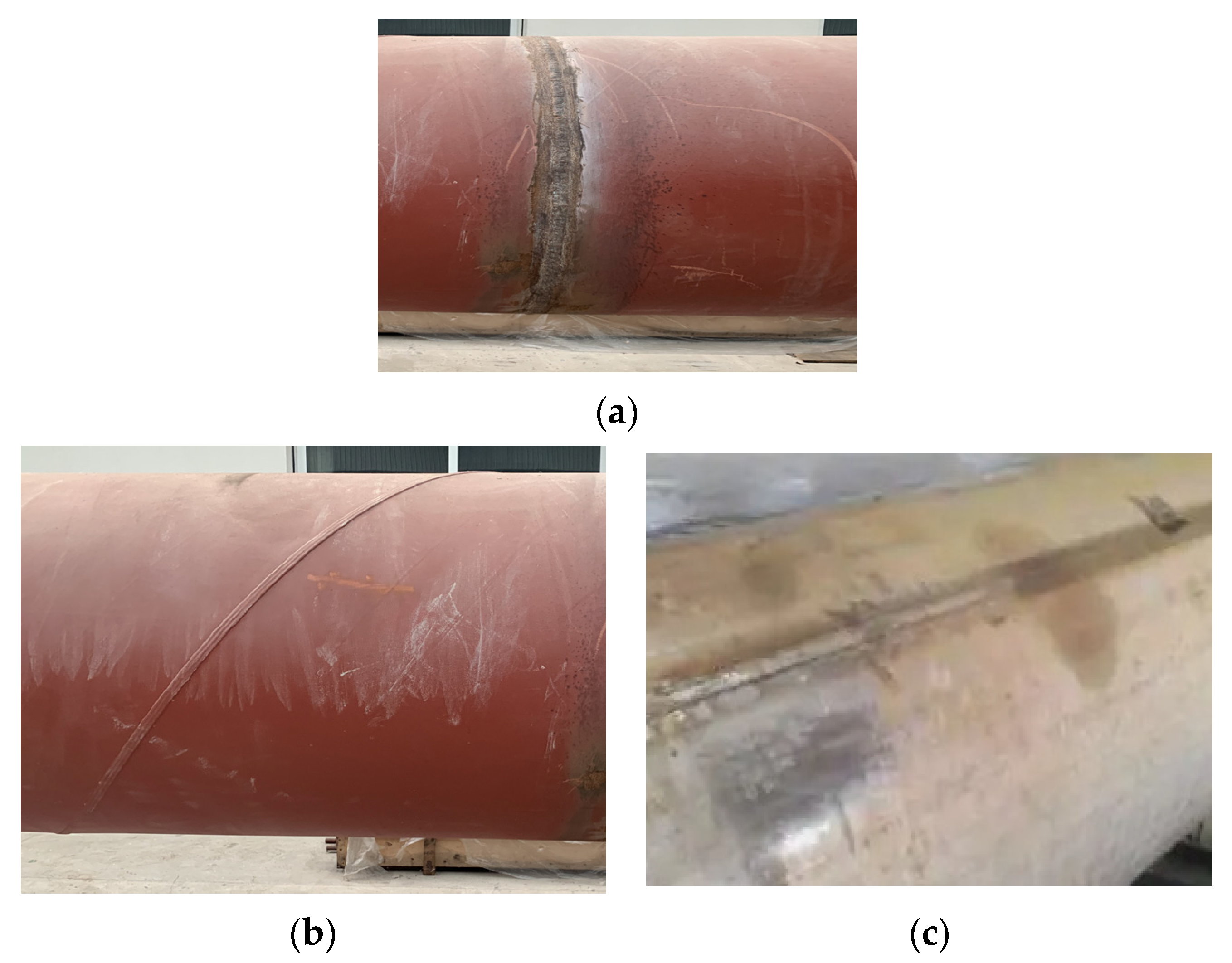
Figure 3. Welds of a pipeline. (a) girth weld; (b) spiral weld; (c) straight weld.
- (3)
-
Special components
The special components of a pipeline usually include the flange, tee, small opening, valve, patch, elbow, etc. Figure 4 shows these special components. The flange and tee are both connections between the pipes, which will form a gap at the joint. The small opening, valve, patch, elbow, and other pipeline components will change the structural characteristics of the pipeline, thus forming a leakage magnetic field.
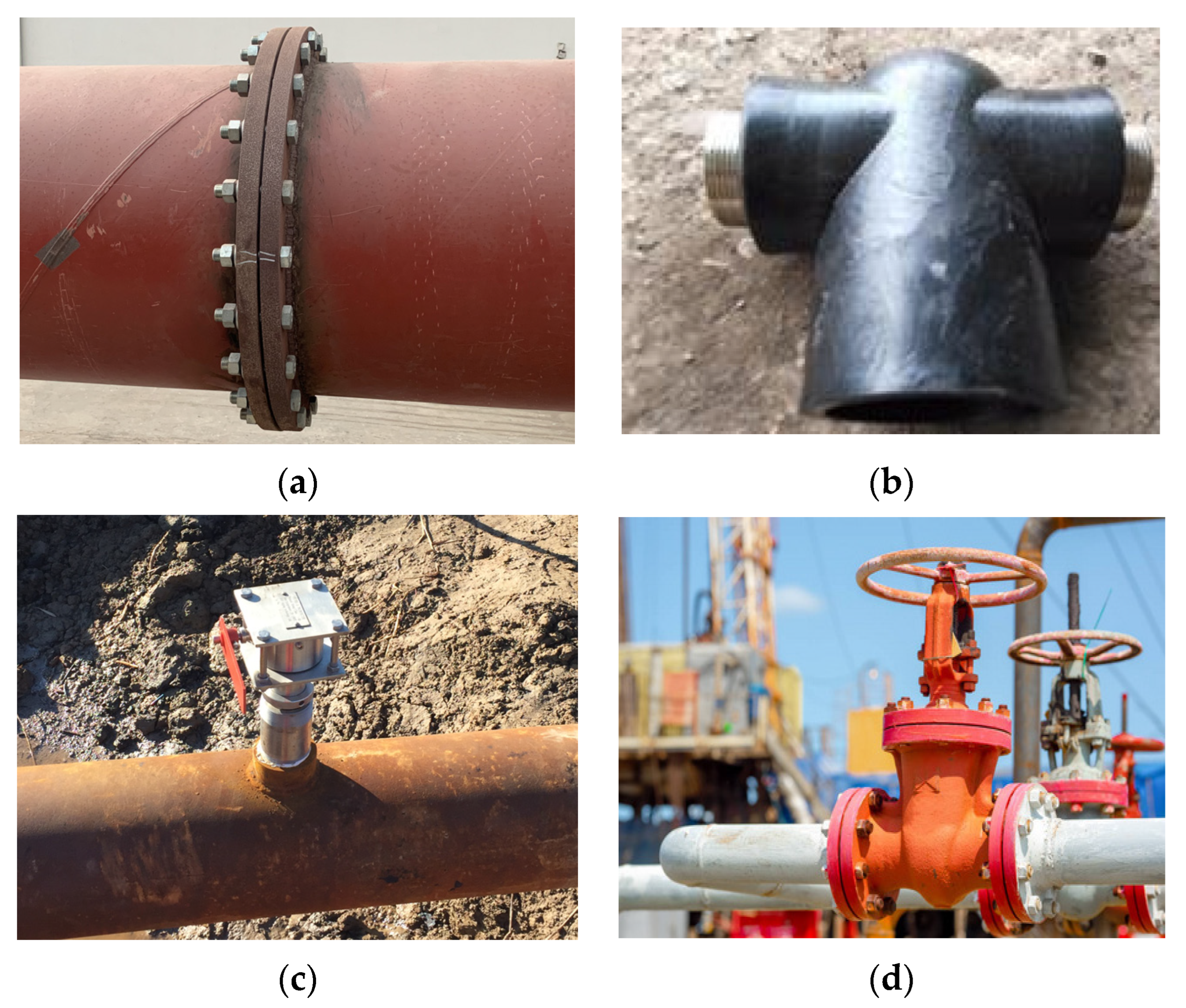
Figure 4. Special components of a pipeline. (a) flange; (b) tee; (c) small opening; (d) valve.
These main anomalies of oil and gas pipelines will cause the distortion of the leakage magnetic field in MFL testing. Among them, the defects are the most important anomalies used to assess the damaged state of pipelines. The welds and special components are common anomalies in pipelines and are mainly used for positioning and calibration. Therefore, after acquiring MFL detection signals, identifying and classifying these pipeline anomalies is of great significance.
4. Pipeline Safety Assessment Process
The process of pipeline safety assessment is shown in Figure 5, which is usually divided into five steps as follows.

Figure 5. Process of pipeline safety assessment.
Step 1: MFL detection and signal acquisition. The structure of the MFL internal detector is shown in Figure 6. It consists of a drive section, detection section, storage section, battery section, and mileage wheel, and a universal joint connects each part. After entering the pipeline, the detector is driven forward by oil and gas pressure, magnetizing the pipeline wall and collecting the MFL signal simultaneously. The collected MFL data will be recorded into the storage device. After the detector comes out of the pipeline, the data will be exported from the detector to the host computer for further display and analysis.
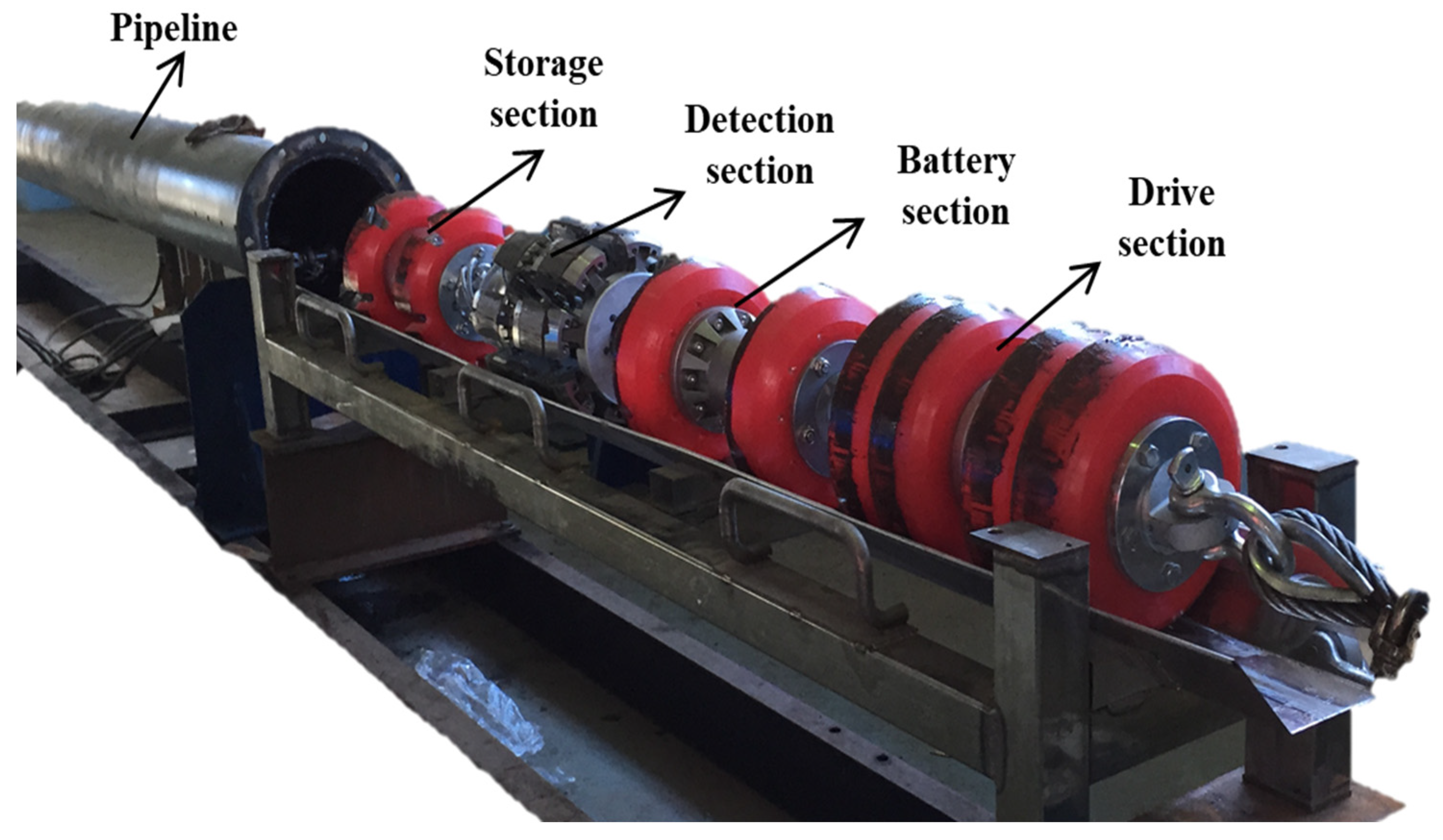
Figure 6. Structure of MFL internal detector.
Step 2: Signal preprocessing and display. Pre-processing for the MFL signal is necessary before comprehensive analysis. The first step is to calibrate the MFL data, considering the inconsistency of each channel sensor. Usually, the channel sensors will be tested before detection to obtain the calibration parameters. The second step is to perform the DC component filtering operation on the calibrated data. The preprocessed MFL signal can be displayed as a curve graph, gray-scale image, or pseudo-color image to present the pipeline MFL signal clearly and completely.
Step 3: Anomaly recognition. After signal pre-processing, it is necessary to effectively identify all kinds of pipeline anomalies from the MFL signal. Anomaly recognition mainly includes two parts: classification and location. The anomaly classification operation can distinguish defects from other pipeline anomalies and obtain the defects’ regions for the following defect inversion and damage assessment process. The accurate anomaly location can guide the subsequent pipeline excavation and repair work efficiently.
Step 4: Defect quantification. After extracting the MFL signal from the defect area, the defect can be quantitatively analyzed, obtaining its equivalent length, width, and depth. The depth of defect is the most important parameter for pipeline damage evaluation.
Step 5: Safety assessment and prediction. The safety assessment and prediction of the pipeline is the last step of the MFL inspection process. It is combined with the defect inversion results, historical data, and pipeline operation parameters to evaluate and predict the state so as to grasp the pipeline operation state more comprehensively.
References
- Murav’eva, O.V.; Len’kov, S.V.; Murashov, S.A. Torsional waves excited by electromagnetic-acoustic transducers during guided-wave acoustic inspection of pipelines. Acoust. Phys. 2016, 62, 117–124.
- Herdovics, B.; Cegla, F. Long-term stability of guided wave electromagnetic acoustic transducer systems. Struct. Health Monit. 2020, 19, 3–11.
- Ravan, M.; Amineh, R.K.; Koziel, S.; Nikolova, N.K.; Reilly, J.P. Sizing of multiple cracks using magnetic flux leakage measurements. IET Sci. Meas. Technol. 2016, 4, 1–11.
- Peng, L.S.; Huang, S.L.; Wang, S.; Zhao, W. A Simplified lift-off correction for three components of the magnetic flux leakage signal for defect detection. IEEE Trans. Instrum. Meas. 2021, 70, 6005109.
- Wasif, R.; Tokhi, M.O.; Shirkoohi, G.; Marks, R.; Rudlin, J. Development of permanently installed magnetic eddy current sensor for corrosion monitoring of ferromagnetic pipelines. Appl. Sci. 2022, 12, 1037.
- Duan, J.Y.; Song, K.; Xie, W.Y.; Jia, G.M.; Shen, C. Application of Alternating Current Stress Measurement Method in the Stress Detection of Long-Distance Oil Pipelines. Energies 2022, 15, 4965.
- Ma, H.M.; Xu, Y.; Yuan, C.; Yang, Y.G.; Wang, J.H.; Zhang, T.; Li, T. Measurement characteristics of a novel microwave sensor based on orthogonal electrodes method. IEEE Sens. J. 2022, 22, 6553–6565.
- Cataldo, A.; De Benedetto, E.; Cannazza, G.; Leucci, G.; De Giorgi, L.; Demitri, C. Enhancement of leak detection in pipelines through time-domain reflectometry/ground penetrating radar measurements. IET Sci. Meas. Technol. 2017, 11, 696–702.
- Quy, T.B.; Kim, J.M. Leak detection in a gas pipeline using spectral portrait of acoustic emission signals. Measurement 2020, 152, 107403.
- Xu, C.; Du, S.; Gong, P.; Li, Z.; Chen, G.; Song, G. An improved method for pipeline leakage localization with a single sensor based on modal acoustic emission and empirical mode decomposition with Hilbert transform. IEEE Sens. J. 2020, 20, 5480–5491.
More
Information
Subjects:
Engineering, Petroleum
Contributors
MDPI registered users' name will be linked to their SciProfiles pages. To register with us, please refer to https://encyclopedia.pub/register
:
View Times:
1.3K
Revisions:
3 times
(View History)
Update Date:
17 Nov 2023
Table of Contents


Notice
You are not a member of the advisory board for this topic. If you want to update advisory board member profile, please contact office@encyclopedia.pub.
OK
Confirm
Only members of the Encyclopedia advisory board for this topic are allowed to note entries. Would you like to become an advisory board member of the Encyclopedia?
Yes
No
${ textCharacter }/${ maxCharacter }
Submit
Cancel
Back
Comments
${ item }
|
${ item.createdUser.fullName }
${ item.createdAt }
${ item.vote }
${ item.reply }
Delete
${ reply.createdUser.fullName }
${ reply.createdAt }
${ reply.vote }
Delete
There is no reply to this comment~
${ item.replyTextCharacter }/${ item.replyMaxCharacter }
Submit
Cancel
More
No more~
There is no comment~
${ textCharacter }/${ maxCharacter }
Submit
Cancel
${ selectedItem.replyTextCharacter }/${ selectedItem.replyMaxCharacter }
Submit
Cancel
Confirm
Are you sure to Delete?
Yes
No