1. Dense Media Separation
1.1. General Characteristics
A dense medium, also known as a heavy medium, is a liquid whose density is higher than that of the lighter fractions of a given granular feed stream. This causes the lighter fraction to float on the dense medium, while the heavier material sinks. Dense media can be comprised of organic liquids (such as bromoform, perchloroethylene, carbon tetrachloride, etc.), saline solutions, or suspended solids
[1]. Organic liquids are expensive, toxic, and often corrosive, making them suitable only for lab-scale sink-and-float analysis of density distribution of samples. Saline solutions, such as NaCl, CaCl
2, or ZnCl
2 are relatively easy to obtain and handle. However, they have a limited maximum medium density of approximately 1.8 g/cm
3 (for ZnCl
2) at room temperature
[2], which may not be high enough, depending on the intended application. Some soluble tungstate salts, such as sodium polytungstate, enable the attainment of solution densities up to 3.1 g/cm
3 [3]. However, their high costs and difficulties associated with their recovery normally restrict their application to lab-scale operations.
Therefore, dense media usually consists of a pulp, which is a mixture of water and finely comminuted solids, with an intermediate density between the phases to be separated. By mixing this pulp with the material to be beneficiated, products with lower and higher densities than the dense medium are obtained, resulting in floated and sunken products, respectively. Ferrosilicon (FeSi) with 15–16% silicon and magnetite powders, with grain sizes ranging from 150 µm to less than 45 µm, are the most used materials (or ‘media’) for preparing dense media due to their ease of recovery and reuse within the processing plant using magnetic separation
[1][3].
A suitable dense medium should achieve the required density with minimal viscosity and high stability (i.e., with no or limited segregation of the material composing the medium). Meeting all these conditions can be complex, as it depends on several factors, such as the solid fraction, grain density, and size distribution of the medium, as well as the presence of contaminants like slimes that may alter the apparent density and viscosity of the medium. Simply, the density of a dense medium can be determined by:
where
𝜙𝑠𝑜𝑙 and
𝜌𝑠𝑜𝑙 are the volumetric solid content and solid density of the medium, respectively. For example, if
𝜙𝑠𝑜𝑙 = 0.3 and
𝜌𝑠𝑜𝑙 = 6.7 g/cm
3 (FeSi), then the medium density would be 2.71 g/cm
3.
Beyond a certain point, typically around 12 centipoise
[1], the viscosity of the medium increases exponentially with density, resulting in a critical density above which the operation becomes impractical due to the significant changes in viscosity caused by even small variations in density. Generally, the critical density corresponds to
𝜙𝑠𝑜𝑙 ≈ 0.4 (about 3.5 g/cm
3 for ferrosilicon), although this can vary depending on secondary factors such as the size and shape of particles and the presence of contaminants, among others.
A less common alternative method to creating a dense medium involves using a “magnetic fluid”, which consists of submicron ferromagnetic particles suspended in water, silicones, or hydrocarbons. These particles are subjected to an adjustable magnetic gradient, which indirectly allows control of the medium’s density. A well-known magnetic fluid is “Magfluid”, composed of an aqueous suspension of colloidal iron salts stabilized with lignosulfonate to maintain particle dispersion
[1].
1.2. Equipment
Dense media separators can be classified into static and dynamic types based on the dominant external force used for the separation process
[3]. In static separators, the dominant force is gravitational, while in dynamic separators, the centrifugal force is predominant. Static separators are basically tanks, vessels, or drums where material (ores or wastes) and a previously prepared dense medium are continually fed, and density separation takes place directly. The light product (floated) overflows over the top to a weir, while the heavy material (sunken) settles at the bottom of the separator. The removal of the sunken material varies depending on the equipment design: fins or baffles, air lifters or pumps (cone-type separators), or bucket elevators or drag conveyors (drum-type separators)
[4]. A gentle agitation is usually provided to keep the medium in suspension (so that the denomination “static” separator is only a convenient approximation).
Static separators are mostly restricted to coarse feeds of around 5 mm or larger, due to the high residence time required to effectively separate finer particles. One alternative to increasing the velocity of particles is increasing the acceleration of the field through the tangential injection of pulp and dense medium into a closed stationary container. Such a feature characterizes dynamic dense media separators, which can generate centrifugal accelerations up to 40 times greater than gravity, allowing the effective separation of materials as fine as 0.1 mm
[3]. Although they facilitate the separation of finer particles, the centrifugal forces that act on dynamic separators impose strict constraints on the stability of the medium. This is due to the occurrence of density gradients caused by segregation of the medium, which require a more robust strategy for separation control.
Dynamic separators can be classified according to the geometry of the separation chamber into cylindrical and cylindrical-conical types. The former is available in a variety of models, such as Dyna Whirlpool
[3], Vorsyl
[5], and Larcodems
[6] separators. The latter type includes traditional dense-medium cyclones, which are widely used in mineral processing.
Dense-medium cyclones consist of two adjacent sections, one cylindrical and one conical (Figure 1). The separation process is achieved by introducing a mixture of the material to be separated and dense medium into the cyclone through a tangential feed inlet near the top of the cylindrical section. The resulting centrifugal force causes the denser particles to move towards the inside of the outer walls of the cyclone, describing a downward motion and being removed as underflow through the “apex”, an orifice located at the end of the conical section. The lighter particles are displaced towards the centre, being captured by an upward spiral flow generated by the pressure drop in the central portion of the cyclone. They are discharged as overflow through the “vortex finder” tube, which is located near the top of the cylindrical section.
Figure 1. Scheme of a conventional dense-medium cyclone.
1.3. Advantages and Disadvantages
In general, dense media separation, if conducted properly, is the technique that comes closest to ideal density separation, since it is relatively unaffected by particle size and geometry. Thanks to its direct mechanism for separating materials with different densities, it has become an obvious choice for preliminary investigation on waste recycling, as demonstrated by early studies on scraps and plastics beneficiation. On the other hand, it requires a high number of accessory operations such as medium preparation, dense-medium recovery and regeneration circuits, and pulp recirculation, which makes it particularly costly for many secondary materials and low-value-added wastes. Another significant challenge in its use for material recycling is the possibility of high losses of dense medium. These losses, which can be as high as 5 kg of FeSi per processed ton
[1], are generally associated with the absorption of the medium by porous materials like foams and rubbers.
2. Counter-Current Flow Separation
2.1. General Characteristics
Counter-current flow separation (CCFS) comprises a range of methods and equipment, wherein the granular mixture is fed into a vessel and interacts with a regulated upward flow of fluid. The upward velocity of the fluid is adjusted to match the settling velocity of the finest particles in the dense fraction
[3], so that only the denser particles can overcome fluid resistance and settle into the underflow, while the lighter particles are carried upward and exit the equipment as overflow.
In hydraulic separators, CCFS can be used for both size classification and density separation, as the terminal velocity (Equation (6)) is influenced by the size and density of particles. However, CCFS classification is typically employed when free-settling conditions prevail, which happens when the solids percentage is below 15% by weight
[7]. On the other hand, density separation is carried out with concentrated pulps, where the occurrence of particle–particle interactions becomes more apparent. When particles are well dispersed in the liquid, forming a pulp or slurry, the pulp behaves as a dense medium with a density equal to that of the pulp, rather than the density of water. As a result, hindered-settling conditions prevail. The combined effect of complex particle interactions, fluid density, and system viscosity makes the modelling of hindered-settling separators more challenging compared with free-settling ones.
The high water consumption per ton processed in CCFS makes the use of dry separators more attractive for recycling applications. Dry CCFS separators necessitate high air stream velocities to compensate for the significantly lower density of air (approximately 800 times lower than water). As a result, the fluid dynamics of separation under dry conditions become more turbulent and challenging to control. Consequently, dry separators generally exhibit lower efficiency compared with hydraulic separators.
Figure 2 illustrates such a situation for a hypothetical separation of polyethylene terephthalate (PET) from polyamide (PA) using CCFS under both wet and dry conditions. It can be noted that, at a water fluidization velocity of approximately 20 cm/s, density separation dominates within the size range of 4–15 mm (Figure 2a). On the other hand, for an air fluidization velocity of 1000 cm/s, the size range operation should be limited to only 3–4 mm to prevent a significant influence of size segregation (Figure 2b). Therefore, a meticulous feed preparation is necessary in the case of dry CCFS, ensuring a narrower distribution of feed sizes to achieve effective density separations.
Figure 2. Terminal velocities of spherical particles of PET and PA in different particle sizes. (a) Terminal velocities in water; (b) Terminal velocities in air.
Despite that, dry CCFS devices (also known as “air classifiers”) are recognized as viable options for treating various types of solid waste. They have proven effective in removing light contaminants such as dust, small foam particles, paper, glass powders, and polymer foils from several waste streams. Some cases include: (a) processing municipal solid waste
[8][9]; (b) removing light loose particles and fibers from shredded automotive scrap, generating the shredder light fraction, also known as “fluff”
[10][11]; and (c) general separation of plastics and metals in metallic and electronic scraps
[12][13][14].
2.2. Equipment
CCFS separators include the so-called fluidized bed separators, also known as hindered-bed separators or teetered-bed separators. These tanks consist basically of cubic or cylindrical shapes in which the material to be separated is fed from the top, being separated according to the differential interaction of fractions with different densities and sizes with the upward flow of water injected from the bottom of the equipment (the light fraction leaves the equipment through overflow, while the dense fractions sink and are discharged as underflow) (
Figure 3a). Among some commercial models, the AllFlux
[15], CrossFlow
[16], Hydrosort
[17], and Floatex
[18] separators can be mentioned, which differ from each other mainly due to the mechanisms employed for material distribution in the feed and injection of the upward water stream. Ultrasonic and electromagnetic sensors are commonly used for measuring and regulating the apparent pulp density and the upward velocity of water, respectively, which are the main controlled operational parameters.
Figure 3. (a) Scheme of a typical hydraulic CCFS separator; (b) Scheme of a ZigZag separator.
Among the hydraulic separators, the Reflux Classifier
[19] is perhaps the newest commercially available equipment for CCFS separation used on a large scale. In this system, instead of the conventional upward flow, the fluidizing water is forced to pass through parallel inclined channels located only a few millimeters apart from each other. Thus, the denser and coarser particles tend to move counter-currently, sliding over the inclined channels and leaving the system as underflow, while the lighter and finer particles move concurrently and are discharged in the overflow. The combined effect of the augmented residence time due to the inclined upward flow and the laminar regime generated by the narrow spacing between the channels allows the separation of materials as fine as 0.15 mm
[20].
Air classifiers feature a vertical tube with one or more air injectors positioned between the tube’s base and central section. When the material enters the tube, it encounters drag induced by the upward airflow. This airflow efficiently lifts lighter particles upward while denser ones settle downward.
One of the most well-known separators in this category is the ZigZag classifier, which consists of an upright rectangular channel with multiple sharp bends (
Figure 3b). This unique design incorporates particle collisions with the channel walls as an additional factor that influences particle motion. As a result, it slows down particle movement, effectively prolonging their exposure to the airflow for an extended duration
[20][21][22]. Kaas, Mütze, and Peuker
[9] have indicated that industrial ZigZag separators have feed rates ranging from 5 to 15 ton/m
2/h, with minimum air velocities of about 2 m/s and a solid-to-air ratio of up to 2 kg/m
3.
One advantage of the ZigZag classifier over straight-channel air classifiers is the constricted airflow in certain zones during its rising through the device. This creates an acceleration-deceleration effect on particles, denominated as “passive pulsing”, which has been demonstrated to be advantageous for density-based separation
[23]. Duan et al.
[12], for instance, showed that the beneficiation of electronic scrap using passive pulsed-air classifiers was more effective than using non-pulsed classifiers. Based on this, so-called “active pulsing air classifiers” have been developed, in which adjustable-frequency air pulses are generated by passing the feed air through a controllable valve
[24]. While their application in urban mining is still under development, they have shown promising results in concentrating valuable metals from spent catalysts and scraps
[14][25].
2.3. Advantages and Disadvantages
Counter-current flow separation is among the most fundamental techniques of gravity separation, featuring equipment with straightforward construction, low cost, and relatively easy operation. Although there are relatively few studies addressing the application of hydraulic separators in the processing of secondary raw materials and wastes, it can be inferred that they can potentially separate wastes into different density fractions, as indicated by Hu and Calo
[26] and Baigabelov et al.
[27], which achieved very good separation results in the separation of mixtures of plastic mixtures such as PVC, PET, polycarbonate (PC), and polystyrene (PS). However, the high water consumption per ton processed may pose limitations for large-scale recycling applications, particularly for low-value-added waste.
Air classifiers, on the other hand, can achieve reasonably satisfactory efficiencies in separating mixtures containing materials with significantly different densities, such as plastics and metals, for example. Their simplicity and low cost make them an excellent option as a first stage of separation for cleaning dense waste, especially when the presence of organic matter and plastics is undesirable. However, their high sensitivity to particle size variations can significantly limit their efficiency or require additional investments in prior stages of feed classification. The use of pulsed-air classifiers (passive or active pulsation) can be an option to minimize the influence of size on density-based separation.
3. Jigging
3.1. General Characteristics
Jigging is a technique that involves the repeated expansion of a particle bed using fluid pulses, momentarily increasing its porosity. This allows grains with varying properties to move relative to each other, resulting in the segregation of particles with distinct characteristics. Jigging differs significantly from dense media and CCFS methods, as in the latter, particles are sparsely distributed in the fluid, creating a flow more akin to a fluidized state. In jigging, however, the grains move collectively in a dense and compacted manner, with friction preventing free flow of particles through the fluid.
The amplitude, frequency, and waveform of the vertical fluid pulse are fundamental operational parameters that define the so-called ‘jigging cycle’, which refers to the pattern of cyclic expansions and contractions experienced by the material passing through the jig. In turn, adjusting the appropriate jigging cycle depends on factors such as the particle size distribution, the density of the materials comprising the bed, and the separation objective, aiming to maximize the effect of specific mechanisms involved in jigging (or minimize the influence of others)
[28].
The so-called thermodynamic theory of jigging, initially proposed by Mayer
[29] and later refined by King
[30] and Tavares and King
[31], is the most widely accepted theory for describing the jigging phenomenon. In this theory, the jigging bed is considered a thermodynamic system, and the pulses simply serve to release the latent potential energy of the bed. The lowered center of mass in the stratified bed, due to denser material at the bottom, results in the lowering of the potential energy of the system, facilitated by the kinetic energy delivered by the fluid during pulsation.
Besides providing insights into the underlying mechanisms of jigging, the thermodynamic model is useful for enabling practical interpretations. In practical terms, the reduction of potential energy involves the compaction (increase in packing density) of the bed, allowing size or shape-based particle segregation to overlap with density-based segregation, if it results in a higher compaction of the system. Thus, for example, particles with a tabular or planar shape will tend to be expelled from a bed of spherical particles, as the packing of tabular particles is more irregular and porous (less compacted) compared with that of spherical ones. Moreover, if the pulse intensity (fluid velocity) is too high (i.e., excessive injection of kinetic energy), it can lead to bed remixing, thereby impairing segregation.
It is important to highlight that jigging is a complex technique, involving intricate particle–particle and particle–fluid interactions, and presenting phenomena that are still not fully understood, such as horizontal segregation, granular convection, and wall effects
[28]. Thus, a theoretical model that encompasses all the particularities involved in the jigging process is yet to be developed.
3.2. Equipment
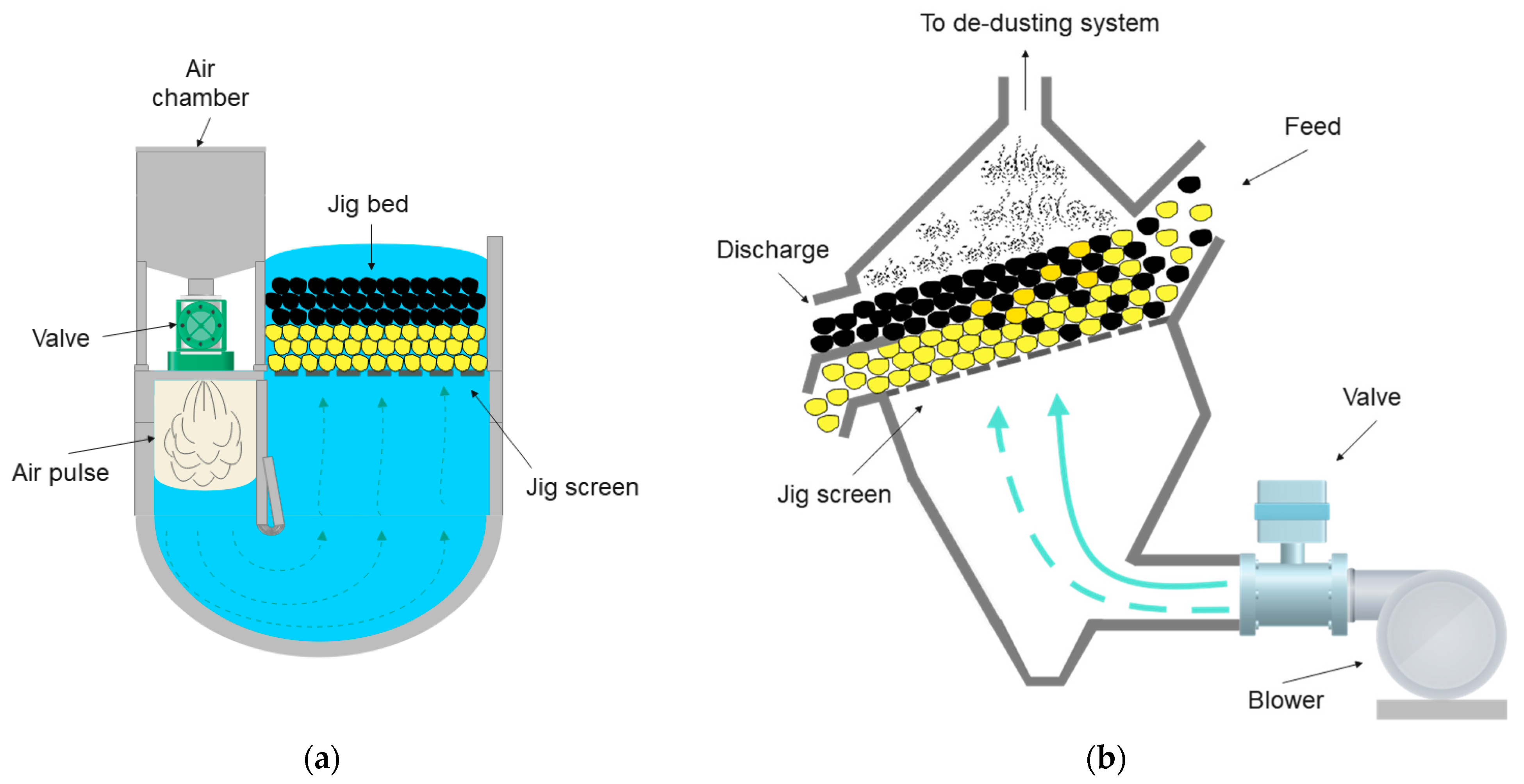
Conventional hydraulic jigs consist of a tank or chamber divided horizontally into two sections: one section containing the screen (perforated plate supporting the bed of material) and another integrating the water pulsation mechanism, which can be comprised of a piston, diaphragm, or air chamber. The latter characterizes modern air-pulsated jigs, such as the Baum and Batac models, which utilize control over the frequency of opening and closing of valves to allow pressurized air to enter the jig chamber, either pushing or suctioning the water, thereby generating the pulsating motion (Figure 4a). The separation density or ‘cut point’, which divides the stratified bed into light and dense products, is controlled by a floating mechanism with a density corresponding to the intended separation density, aligning its vertical position in the bed with the cut point height. Air-pulsated hydraulic jigs represent the state-of-the-art in mineral beneficiation and tend to provide excellent separation results for solid waste such as CDW and slags.
Figure 4. (a) Scheme of a typical air-pulsed hydraulic jig; (b) Scheme of a dry jigging equipment.
On the other hand, dry jigs consist of a single chamber containing the screen through which an upward pulse of air is injected from the base of the equipment (Figure 4b). The pulse is generated by the passage of an air stream generated by a blower through a rotary piston valve, whose rotation frequency can be controlled and directly related to the frequency of the air pulse. Prior to passing through the valve, a portion of the air stream is diverted to provide a continuous flow of air at a lower flow rate than the pulsating flow. This continuous flow increases the porosity of the bed, minimizing the occurrence of short circuits during the passage of the upward pulse of air. Nuclear density sensors are placed close to the deck’s discharge end, allowing control over the bed level and the cut height.
Dry jigs perform well in separating wastes with significantly different densities, such as plastics and wood from rocks and metals. In some specific cases, like separating gypsum from CDW, they are also very effective. Although their unit efficiency is lower compared to that of hydraulic jigs, it can be compensated, in some cases, by employing multiple stages of separation. Moreover, prior research has demonstrated the potential of dry jigs as multi-separators, enabling the segregation of light organic materials (such as paper, plastics, etc.) from a dense bed, while the conventional stratification process occurs. This allows them to function effectively as ‘two-in-one’ separators.
Some jig models are specifically designed for processing waste, particularly plastics. One of these is the “hybrid jig”, which incorporates an air bubbler at its base to exploit differences in hydrophobicity among particles, combining aspects of flotation with jigging. Another model is the “reverse jig”, where the screen is positioned above the bed to retain and facilitate the separation of plastics lighter than water. Specifically tailored for separating extremely lightweight materials, these jig models enable the separation of plastics with very close densities, such as polypropylene (PP) and high-density polyethylene (HDPE)
[32].
3.3. Advantages and Disadvantages
Jigging is by far the most robust gravity separation technique applicable in the processing of coarse solid wastes (above 0.75 mm). It is more cost-effective and less sensitive to fluctuations in the properties of the liquid medium (in the case of hydraulic jigs) compared with dense-medium separators, and it can operate over a wider size range than counter-current flow separators. Like CCFS separators, hydraulic jigging requires significant water flow rates (up to 6 m
3/h of water per m
2 of screen area), making water recycling crucial in the plant. However, unlike with dense-medium and CCFS separation, it is not necessary for the water to be clarified, as the presence of slimes does not significantly influence the separation process
[1].
Similarly, dry jigging is the primary option for dry gravity beneficiation of coarse materials, competing with sophisticated techniques of sensor-based sorting (SBS). For instance, previous work involving the treatment of construction and demolition waste (CDW)
[33] indicated that dry jigging achieved removal efficiencies of impurities such as organics, wood, and gypsum over 90%, which was comparable to that reported for near-infrared SBS
[34]. Its main disadvantage is related to the general limitations of dry beneficiation, including the need to operate with relatively coarse material (+1 mm) and within a narrower size range, compared with hydraulic jigging, to minimize the effect of particle size on the separation. Additionally, the requirement for high air velocities (in the range of tens of m/s) may result in excessive dust generation, necessitating the use of dust collection systems attached to the equipment.
4. Flowing-Film Separation
4.1. General Characteristics
Flowing-film separation encompasses a variety of techniques in which gravity separation is achieved by flowing a pulp over an inclined surface at a constant velocity. It is probably the oldest method of gravity separation, and its application in the beneficiation of various minerals was already widespread in medieval times, as demonstrated in the classic text ‘De Re Metallica’ (‘On the nature of metals’) written by Georgius Agricola in 1556
[35].
Sluices are the most basic and oldest devices used for flowing-film separation, consisting simply of an inclined surface over which the pulp flows to allow the sedimentation of the dense fraction while discharging the light fraction along with the water film. The surface of the sluice can feature riffles to trap the dense material and prevent its re-fluidization, or it can be a smooth surface with pulp splitters positioned at the discharge point to separate the light product from the dense one, as seen in the ‘pinched sluice’
[3]. While widely used in artisanal gold mining, there is little evidence of the modern application of sluices in recycling, as more efficient and sophisticated options are available. Nonetheless, their operation has served as the basis for designing modern flowing-film separators. Among these, two types of separators stand out in urban mining applications: spiral concentrators and shaking tables. They are described in detail in the following section.
4.2. Equipment
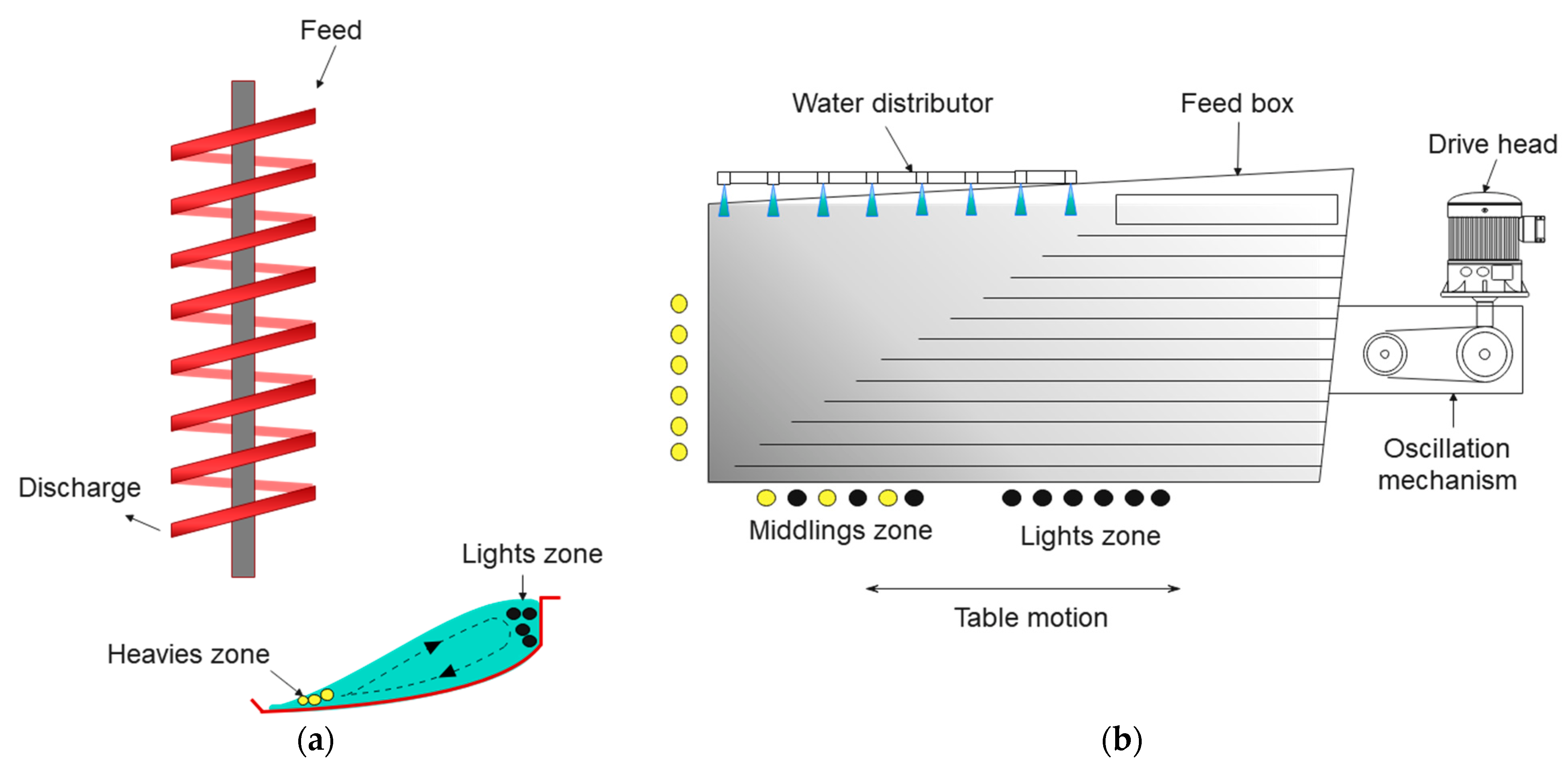
The spiral concentrator consists essentially of a helical-shaped channel with a modified semi-circular section, supported by a central column, into which a feed slurry is introduced through a feeding box positioned at the top of the equipment (
Figure 5a). The separation occurs due to the combined action of gravitational, centrifugal, drag, dispersive, and frictional forces as the slurry descends in a spiral motion
[1]. Denser particles concentrate in the lower portion of the fluid film and are displaced towards the central column (inner edge of the trough) along with the liquid layer. In contrast, lighter particles in the upper portion of the fluid film are dragged towards the outer edge of the trough due to the more intense centrifugal force in that region. The result is the generation of a radial segregation profile within the spiral, with denser particles positioned in the inner portion and lighter particles in the outer portion of the helicoidal trough. The separation of products can be carried out along the channel, using flow diverters, or at its end, using adjustable splitters.
Figure 5. (a) Scheme of a spiral concentrator; (b) Scheme (top view) of a wet shaking table.
Particle separation in spirals involves complex mechanisms, such as the influence of the Bagnold force
[36][37], that can lead to the so-called ‘reverse classification’
[3], where fine particles tend to concentrate with the dense ones, and coarse particles tend to concentrate with the light ones. Also, the separation dynamics occur within the ‘secondary flow’ of the spiral (
Figure 5a), which moves radially from the outer to the inner trough, with a significantly lower magnitude than the primary downward flow of the fluid. Recent work by Ye et al.
[38] has explored the possibility of enhancing the secondary flow through variations in the spiral design and operation, such as the reduction of the pitch (vertical distance between similar points in successive turns of the spiral helix) and the flow rate.
The operational size range that can be processed in spirals is typically 3 mm to 0.075 mm
[39], with preferred narrower intervals. The feed rate is generally considered the main operational variable, showing a tendency to decrease recovery and increase the grade of dense product as the feed rate increases, due to the shorter residence time in the trough. However, recent experimental work by Boisvert et al.
[40] indicated that the fluid volume in the trough of the spiral varies proportionally to the feed rate, meaning that the residence time is relatively insensitive to the feed rate.
Shaking tables are devices that perform density-based separation with the help of horizontal shearing resulting from the oscillatory motion of the surface on which the flowing film flows. They consist of a rectangular or rhomboidal deck partially or fully covered with riffles distributed along its length (
Figure 5b). Oscillations are induced along the horizontal axis of the table (parallel to the riffles) by a drive mechanism located near the feed box. The oscillations have an asymmetrical profile, with a slow forward stroke followed by rapid return strike to promote particle slippage towards the discharge
[41]. Water is distributed along the entire table surface, forming a film that flows perpendicularly to the riffles, in the transverse direction of the deck, following its slope (from 0 to 6°)
[42]. The Wilfley table, developed in 1896, is one of the most popular models
[2].
According to Sampaio and Tavares
[1], particle separation on shaking tables can be conducted within the range of 2 mm to 40 µm and is governed by the combined action of three mechanisms: (a) differential velocity of particles in the water film; (b) asymmetric oscillating motion of the deck, transverse to the water film; and (c) stratification of particles between the riffles. The combined action of these mechanisms, along with the riffles’ configuration (varying in height as they approach the dense product discharge), generates a diagonal separation profile, where dense and fine materials are more influenced by the deck oscillations due to their entrapment between the riffles, tending to move along the table surface and be discharged in the quadrant opposite to the feed. On the other hand, light and coarse materials are more susceptible to the flowing-film action and are rapidly washed away by the wash water. The separation of products is achieved with a splitter positioned in the discharge chute. Feed variations, including grade, feed rate, and solids concentration, can significantly impact the positions of the product bands on the table. Employing automatic splitters equipped with color-sensitive image sensors may enhance process efficiency.
Air tables, also known as pneumatic tables, operate on principles similar to those of wet shaking tables. Originally designed for seed separation in the food industry
[43], they have gained attention in recent years for recycling applications, such as sorting of bottom ash from municipal solid waste incinerators
[44] and separation of polymers from ceramics and metals contained in auto shredder residue
[11]. Its operating principle combines the induction of particle sliding on the deck through longitudinal oscillations, like those used in shaking tables, with the injection of a continuous upward air flow, similar to that used in air classifiers. Therefore, although not strictly a flowing-film separator, its design and operation closely resemble that of a shaking table.
Air tables have perforated decks (with openings smaller than the smallest particle in the feed) through which an upward air stream of up to 4 m/s can be adjusted. The frequency of deck oscillation is also adjustable, reaching up to 13.3 strokes per second
[43]. The overall effect of deck oscillation is to spread and lift denser particles (in greater contact with the surface) towards the higher side of the table, while lighter particles are fluidized by the air stream and drift down along the deck’s lateral inclination due to gravitational pull. Both fractions are channeled towards the discharge due to the longitudinal slope of the table. Splitters positioned at the opposite end of the feed allow for the separation of discharges into dense and light product. Operational parameters like airflow velocity, vibration frequency, and lateral and longitudinal slope of the deck may be adjusted in controllers attached to the table
[45].
4.3. Advantages and Disadvantages
From a broad perspective, the versatility of the flowing-film separation technique lies in its ability to adapt its underlying physical principle to diverse equipment configurations, each offering complementary attributes. Spiral concentrators, for instance, are cost-effective, with no moving components, and easy to implement, making them well-suited for initial concentration stages in processing circuits (‘rougher’ stages), where the goal is to eliminate part of the contaminants while ensuring high product recovery. Conversely, shaking tables stand out as the most selectively efficient non-centrifugal gravity separators, yielding substantial enrichment ratios (concentrate-to-feed grade ratio). Consequently, it is a common practice in mineral processing that circuits employing spiral concentration are succeeded by shaking-table processes (‘cleaning’ stages, in which the goal is achieving the target grade). Also, both have the advantage of enabling the visualization of product separation on their surfaces during operation, facilitating image data acquisition for use in supervisory control in modern machine vision systems
[46][47].
However, a common drawback among flowing-film separators is their limited unit processing capacity (tons processed per square meter of equipment), requiring the deployment of multiple units in parallel to achieve a specific processing capacity. For instance, the handling capacity of shaking-table units ranges from up to 2 ton/h for coarse sand (about 1.5 mm) to as low as 0.5 ton/h for material below 100–150 µm
[3]. This attribute is recognized in the process industry as a significant ‘footprint’ and could entail the requirement for a substantial area for equipment installation. Furthermore, the utilization of multiple lower-capacity units introduces maintenance complexities due to the need for coordinated operations among these units. This can pose challenges in terms of integrating them into the control system, and a broader range of replacement components and parts. Not surprisingly, due to their limited unit capacity, flowing-film separators have been facing growing competition from intensive centrifugal separators.
Finally, it is noteworthy that spiral concentrators may necessitate operation within very narrow size ranges (e.g., 0.8–0.4 mm, 0.3–0.1 mm, etc.) to achieve optimal performance. This is attributed to their hydrodynamics, which tend to include coarse or excessively fine particles, even if dense, in the light product fraction
[1].
5. Centrifugal Separation
5.1. General Characteristics
Centrifugal separators, also known as enhanced gravity concentrators, operate by harnessing controlled centrifugal acceleration to efficiently separate fine and ultrafine particles. Their main distinction from other separators involving centrifugal force (such as cyclones, spirals, etc.) lies in their adjustable centrifugal acceleration achieved through regulating the rotation speed of a container, often with a cylindrical or truncated cone shape, rotating at high velocities. This dynamic design contrasts with conventional gravity separators, where the control volume remains fixed. Hence, in addition to its ability to concentrate particles smaller than 10 µm, centrifugal separation enables high unit processing rates for ultrafine materials, which is often unattainable through conventional gravity-based separation methods.
The realization that centrifugal separation enhances fines separation dates to the 19th century, as evidenced by the earliest patents
[1]. However, due to the lack of abrasion-resistant materials for high-speed operations, its substantial development only became feasible from the 1980s onwards. Since then, centrifugal separators have competed with other physical techniques for ultrafine material separation, like froth flotation and high-intensity magnetic separation.
5.2. Equipment
The core element of all centrifugal separators is a container (‘basket’) with either a cylindrical or truncated cone shape, rotating at high speeds (usually more than 1000 rotations per minute). The material to be separated is introduced as slurry through a conduit at the central base of the container, subsequently propelled towards the lateral walls by the centrifugal force resulting from the cone’s rotation (Figure 6). The slurry forms a thin film on the inner walls of the container, flowing upward due to the container’s lateral wall inclination, especially when it has a truncated cone shape. It is primarily during this upward movement of the slurry that the mechanisms of density, size, and shape segregation of particles come into play. These mechanisms vary depending on the specific centrifugal separator model used.
Figure 6. General scheme of centrifugal gravity separator.
The main centrifugal gravity separation equipment includes the Knelson separator, Falcon separator, and centrifugal jigs. There is also a fourth model, known as the Multi-Gravity Separator (MGS), whose application, however, is more suitable for laboratory or pilot scale investigation. All of them can be viewed as centrifugal adaptations of conventional gravity separation techniques.
In the Knelson separator, a conical container is equipped with equidistant rings along its inner surface
[48]. The pulp fed near the base of the container is subjected to accelerations of up to 180 G (i.e., 180 times the acceleration due to gravity), although most units operate at approximately 60 G
[49]. Bed compaction is prevented by counter-pressure water injection (from outside to inside) through perforations distributed along the container surface. By controlling the water injection pressure, it is possible to selectively fluidize the lighter particles, which are then expelled and carried over the rings to the light product discharge area at the top of the container. Dense particles trapped within the rings are periodically removed by briefly stopping the rotation of the container. This enables the particles to be washed away, directed towards a discharge orifice located at the base of the container. The separation process in the Knelson can thus be viewed as a centrifugal version of counter-current flow separation, where the separation arises from the interplay between centrifugal forces (container rotation) and drag forces (fluidization water)
[50].
Recent studies
[51][52] have evaluated Knelson separators using air as the medium to explore the dry separation of synthetic mineral mixtures. While notable recovery of dense materials was achieved under optimum conditions, the concentrate grades were considerably poorer compared with those attainable with wet operating conditions.
The Falcon separator also features a truncated cone-shaped container but distinguishes itself from the Knelson separator by lacking rings and not requiring any fluidization water, enabling higher centrifugal accelerations. The latest model, the Ultrafine (UF) Falcon, can reach accelerations of up to 600 G and is designed to handle materials with particle sizes ranging from 3 to 75 µm
[53]. During operation, the pulp fed at the bottom of the cone is distributed across the smooth walls by the centrifugal acceleration generated by the rotating bowl, progressively moving upwards. In this process, dense particles tend to concentrate against the wall within the liquid film, while lighter particles are carried upward by the water flow, resembling flowing-film separators
[54]. The upper part of the container has a cylindrical shape parallel to the rotation axis, nullifying the axial component of the centrifugal force (which lifts the pulp). At the top, a retaining ring, with a smaller diameter than the container, holds the dense fraction against the wall, allowing the light fraction to exit as overflow. In some models, pneumatic valves positioned near this retention zone enable continuous removal of the dense product
[55].
The centrifugal jig consists of a cylindrical container with openings (the container itself can be made of a woven mesh screen) where ragging material formed by small steel spheres or similar material spreads on the container surface during operation
[56]. In operation, the pulp fed at the center of the container spreads over its internal surface and moves upwards, as in other centrifugal separators. The container is placed within a pressurized water jacket, whose external casing is equipped with diaphragms generating radial pulses. Thus, during its ascent, the bed undergoes the effect of pulses similar to those occurring in conventional jigs (though horizontal), leading to the stratification of the bed. Dense and fine particles pass through the ragging bed and the screen opening into the hutch, subsequently flowing through a spigot, and gathering in a reservoir
[55]. Light particles are carried away before passing through the ragging material, and then leave the system as overflow at the top of the equipment.
Unlike other separators, where process control can be simplified to adjusting the container rotation (and water pressure for fluidization, in the Knelson separator), centrifugal jigs have several other operational variables, such as water pressure, thickness of the ragging layer, amplitude and frequency of pulsation, and screen opening
[1], which can make the operational adjustment particularly complex.
5.3. Advantages and Disadvantages
In general, centrifugal separation is the only viable option for gravity separation of ultrafine materials (less than 75 µm), with the exception, in some cases, of shaking tables. By allowing fine adjustment of the field force acting in the separation (the centrifugal force), they make it possible to achieve high unit processing rates (ton/hour of solids) for fine and ultrafine materials, which would require dozens or even hundreds of non-centrifugal units (such as spirals and tables) to match. Furthermore, being compact and high-capacity equipment, they allow the concentration of operational and maintenance efforts on a few processing units.
Centrifugal separators operate with a maximum size of 2 mm and should preferably handle finer material. Consequently, they are suitable for wastes below this particle size or those that have been previously milled to liberate the target elements. The design and operation of these separators are primarily tailored to their original application: the recovery of fine alluvial gold, often with very low grades
[57]. As a result, they typically yield a very low mass fraction of dense product, around 0.1%
[50]. Although continuous and fully automated models can yield significantly higher, the mass yield of the dense product will likely be considerably lower than in many non-centrifugal separators. Similar scenarios could arise in urban mining processes, such as recovering precious metals from printed circuit boards or platinum-group metals from automotive catalyst waste, where target element contents are in the ppm range. However, references to these applications are still scarce in the literature.
Lastly, it is noteworthy that centrifugal separators have a relatively high water consumption. The centrifugal jig equipment, in particular, can reach water consumption levels of up to 15 m
3 per ton of processed solids
[1].
 +1 credit