 +1 credit
| Version | Summary | Created by | Modification | Content Size | Created at | Operation |
|---|---|---|---|---|---|---|
| 1 | Andre Vervoort | -- | 1403 | 2023-11-01 10:18:28 | | | |
| 2 | Catherine Yang | -9 word(s) | 1394 | 2023-11-03 01:52:56 | | |
Video Upload Options
The strength of rock is a non-intrinsic property, and this means that numerous parameters influence the strength values. In most laboratory experiments, specimens are free of stress at the start of the tests, and the load is increased systematically until failure occurs. Around excavations, the opposite path occurs, i.e., the rock is in equilibrium under a triaxial stress state and at least one stress component decreases while another component may increase. Hence, the stress paths in classic laboratory experiments are different from the in situ stress paths. In the research presented, the effect of these different stress paths on the failure processes and failure envelopes was studied. The micro-fracturing when loading rock (from zero or low stress state) until failure was different from the micro-fracturing when unloading rock (from the in situ stress state) until failure. And, hence, by this difference in weakening processes, the failure envelopes were significantly different. The conventional loading resulted in the largest strength and, thus, overestimated the rock strength in comparison to the real in situ behavior. This finding, after being confirmed by additional experiments, will have a direct effect on how one characterizes rock material and on the design of rock excavations.
1. Introduction
One of the most significant challenges in rock mechanics is understanding the mechanisms involved in the behavior and failure of rock. Hence, numerous research projects focus on conducting laboratory experiments and simulating them. One of the key issues in conducting such investigations is to get a better understanding of the variability and uncertainty of rock characteristics, e.g., moduli, uniaxial compressive strength and Brazilian tensile strength. The strength of rock is a non-intrinsic property, which means that its value is influenced (1) by the geometric characteristics of the specimen (e.g., its volume, shape, and orientation), (2) by environmental aspects (e.g., humidity and temperature), (3) by the loading rate (e.g., conventional loading rates, dynamic loading, and creep), and (4) by the test set-up. The three most common tests are the Brazilian tensile tests, uniaxial or unconfined compression tests, and conventional triaxial tests. Based on the combination of these tests, the failure envelopes are determined, and the latter are used as input for design projects.
Nearly all such experiments are started from an isotropic stress state, followed by an increase in at least one of the principal stress components. The initial isotropic stress state is either a fully zero-stress state or a non-zero, isotropic stress state. The latter stress state is created by increasing equally the three principal stresses starting from a state of zero stress. No damage should be induced during the initial equal stress increase. From a practical point of view, such loading experiments are entirely logical. Cored or cut specimens are, by definition, not loaded. However, as is well known, this procedure is the opposite of what happens in situ. The rock is in equilibrium under a state of triaxial stress, and at least one stress component decreases due to the excavation, resulting in damage (e.g., micro-fracturing) and, possibly, even in the failure of the rock. The facts that unloading stress paths occur around excavations and can result in fracturing and failure is common knowledge for all rock mechanical engineers. The most illustrative example of this is the discing phenomenon that occurs when cores are drilled in deep boreholes[1].
The research presented recently[2] aimed to evaluate with an open mind if different stress paths could lead to different failure envelopes. A distinct element model was used, whereby, it was essential that (micro-)fracturing is being integrated into the simulated failure process[3]. The study focused on a small representative volume element (RVE). However, the values of the various input parameters were based on past calibration of laboratory experiments[4][5]. The behavior of the RVE model was also verified by modelling published laboratory experiments applying complex stress paths[6].
2. Loading and unloading stress paths
Three basic types of stress paths were modeled in 2D[2]. All three started from an isotropic stress state, including a zero-stress state. The first type was characterized by an increase in successive steps of the major principal stress until failure, for a constant minor principal stress. This stress path is similar to the conventional compressive testing, but it is not exactly the same. This type of stress path was abbreviated as S1(loa),S3(=). The second type was just the other way, S1(=),S3(unl), i.e., the minor principal stress was decreased and the major principal stress remained constant. The third type was a combination of the previous two types. The major principal stress was increased, and the minor principal stress was decreased with the same stress increments. This type of stress path is abbreviated as S1(loa),S3(unl). In comparison to the previous two types, the change in deviatoric stress was larger for the third type.
The simulations that started from an initial isotropic stress state, followed by unloading one stress component, resulted in the weakest failure envelope (Figure 1). The simulations close to the conventional loading resulted in the strongest failure envelope and, thus, significantly overestimated the real in situ strength. The third basic type of stress path was the simultaneous increase in the major principal stress and decrease in the minor principal stress with the same absolute stress increments. The failure envelope of this third type was situated between the two previous envelopes. If the second type of stress paths was applied, but starting from an anisotropic stress state, the failure envelope for a large anisotropy moved closer to the one of the conventional loading paths[2]. For these additional simulations, the initial minor principal stress was decreased.
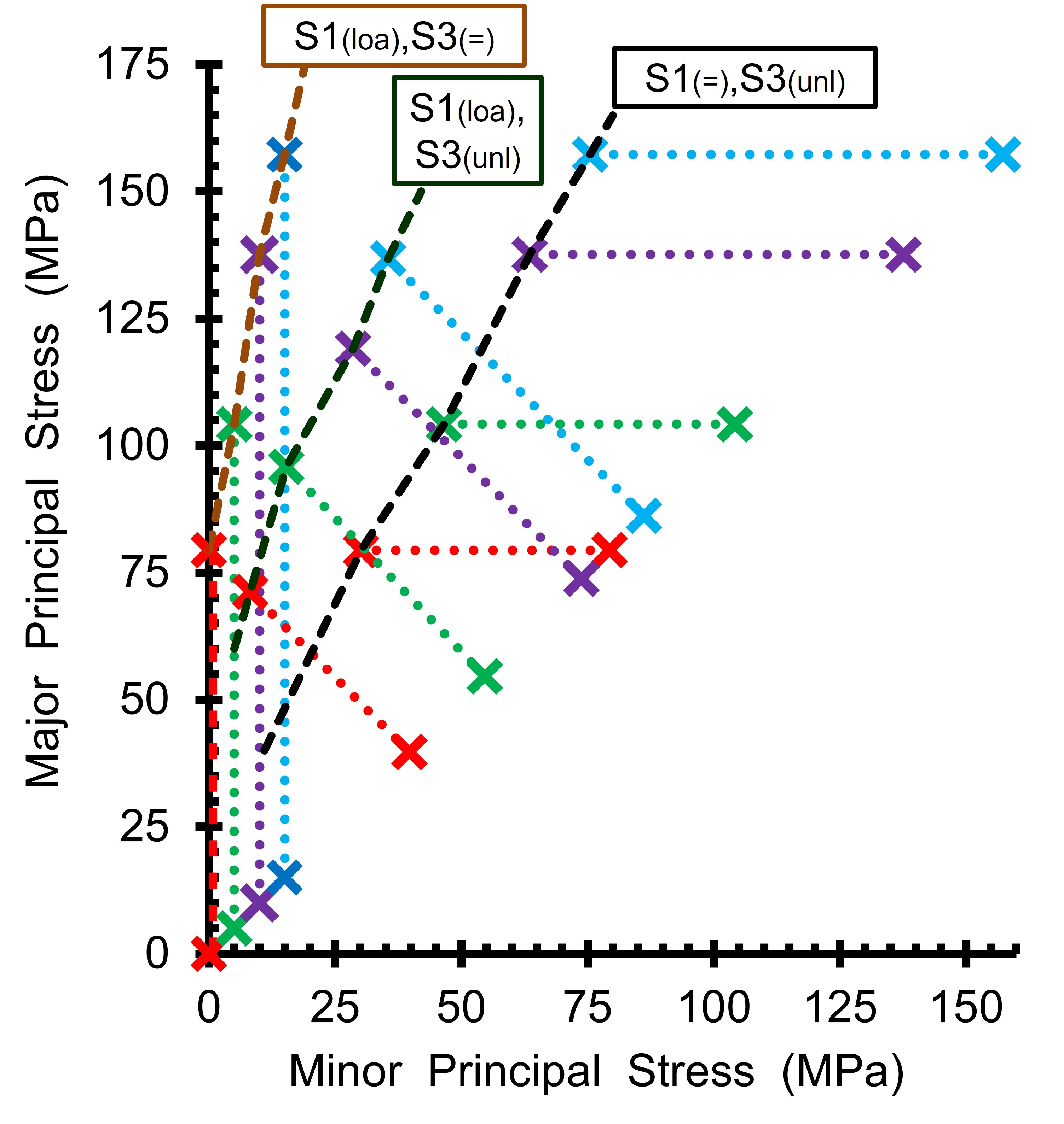
Figure 1. Failure envelopes for the three basic types of stress paths (i.e., uniaxial loading (S1(loa),S3(=)), uniaxial unloading (S1(=),S3(unl)), and simultaneous loading and unloading (S1(loa),S3(unl))[2]. The start of each stress path (i.e., an isotropic stress state) and failed stress states are indicated by crosses.
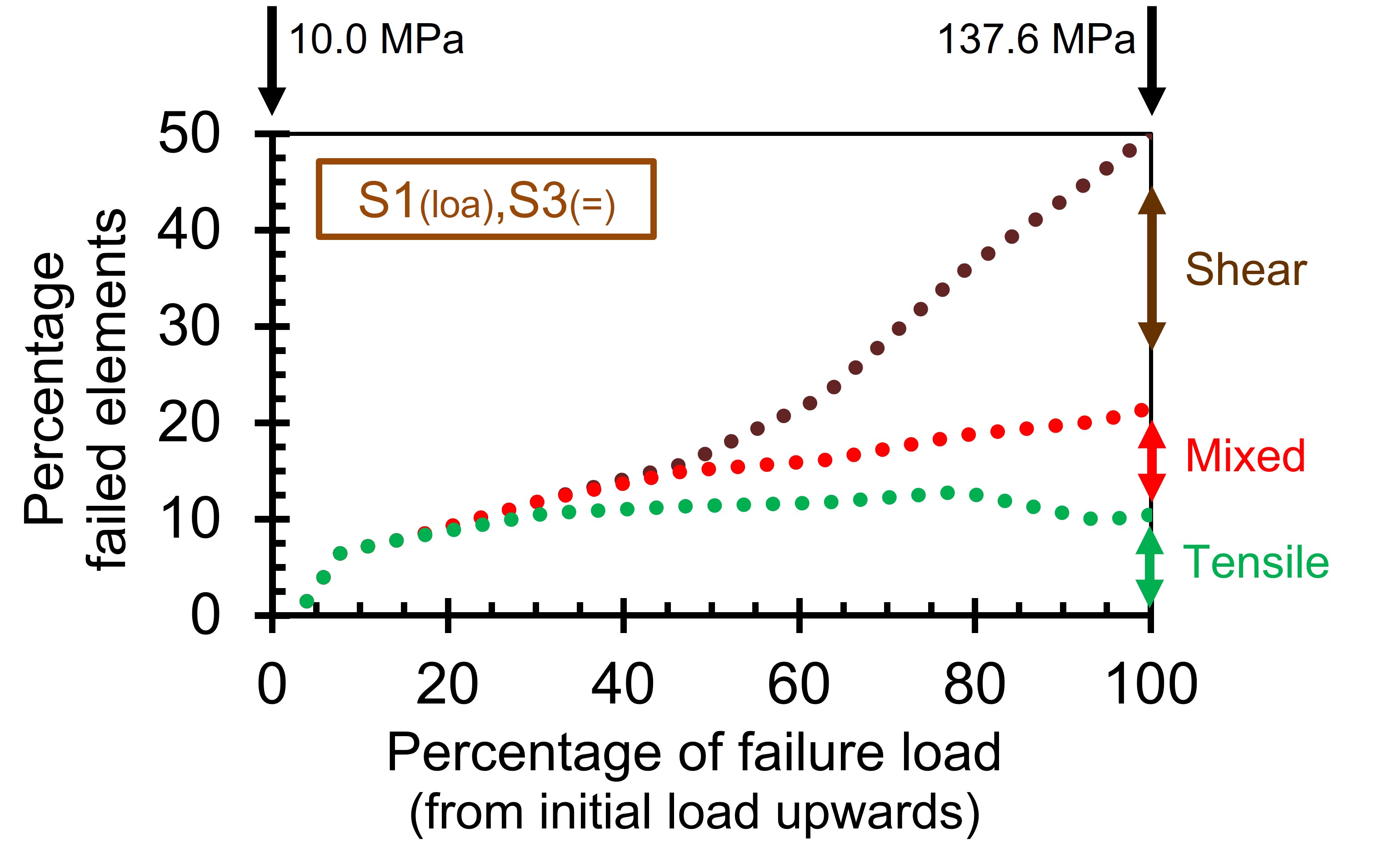
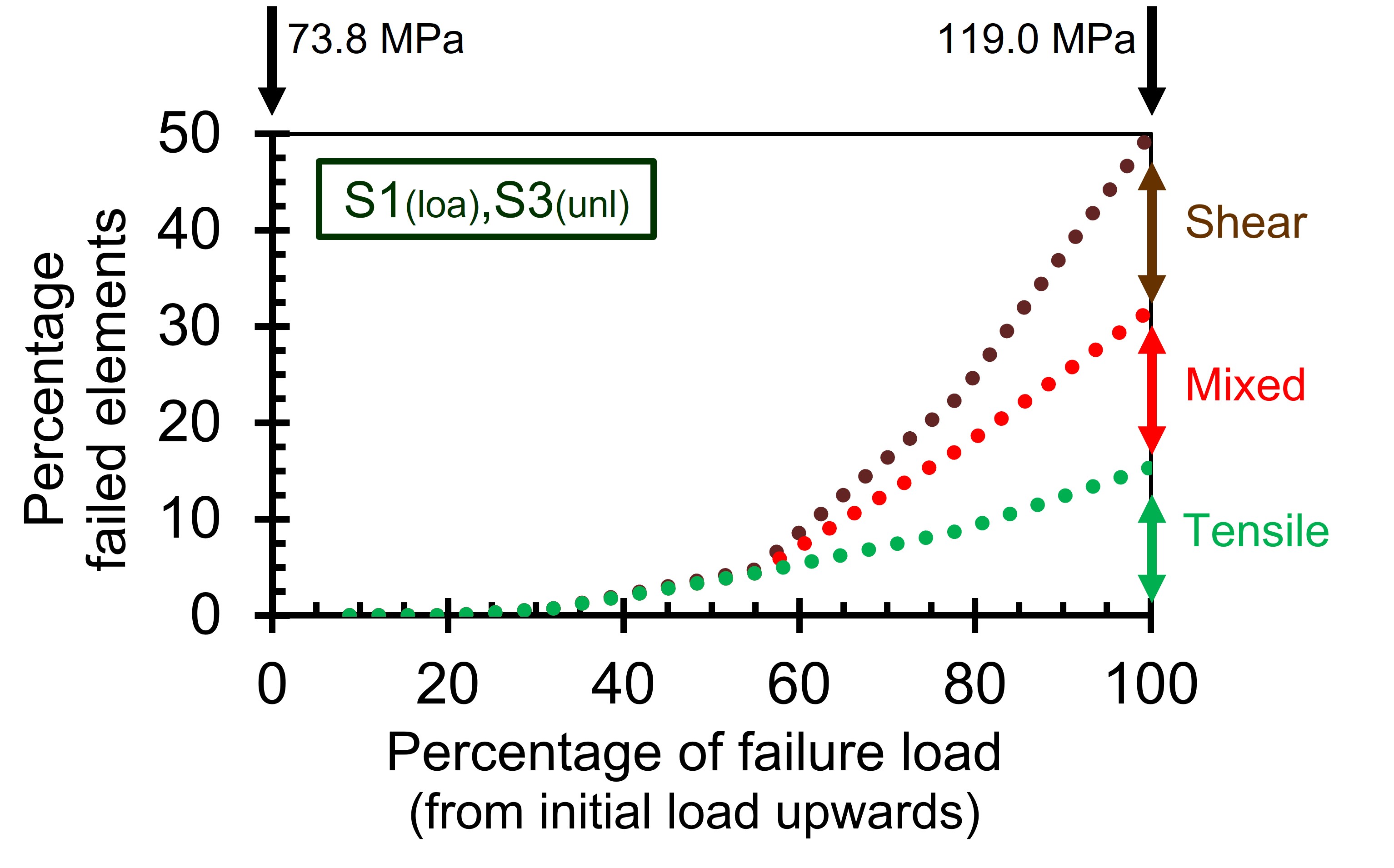
The variation of the fracture mode (i.e., tensile, shear, or mixed) during the stress changes showed some interesting observations (Figure 2). The start of all (micro-)fracturing in the simulations was characterized by tensile failure. This tensile (micro-)fracturing started at small load increases of the major principal stress for the stress paths close to the conventional loading experiments (Figure 2a). At the end of the stress path, the predominant fracturing mode was shear. At the point of macro-failure, the sum of the proportion of shear and mixed modes varied between 64% (unconfined loading) and 82% (largest confinement stresses) of all activated contact elements. For the simulations of the two other basic stress paths with an unloading component (with and without an increase in the major principal stress), no activation occurred in the first 20% to 30% of the entire stress interval until failure (Figure 2b). At the point of macro-failure, no activation mode of the three was predominant.
a.
b.
Figure 2. Variation of the contact failure modes (i.e., tensile only, shear only, and mixed mode) as a function of the stress path, i.e., from the initial isotropic stress state until the load level of failure, corresponding to 50% failed contacts[2]. Two types of stress paths are presented as an example. The initial and final failure loads in absolute values are presented at the top of each graph. (a) Uniaxial loading, S1(loa),S3(=), major principal stress levels are presented; (b) simultaneous loading and unloading, S1(loa),S3(unl), major principal stress levels are presented.
3. Discussion
Although the original aim of the study certainly was not to suggest a revolutionary change in how rock specimens should be best tested in the laboratory. However, one could not deny at the end of the study, that the impact of the stress paths was in some combinations significant. Strength reduction values of up to 40% were calculated. These strength reduction values in the simulations seemed to be realistic when compared to some published laboratory experiments[6][7][8]. Therefore, it is advisable for certain projects and from time to time to also apply stress paths in laboratory, which are closer to the in situ stress paths. This will help the rock mechanical community to better understand the behavior of in situ rock. A change in the way rock is characterized has a direct impact on the design of rock excavations in a high-stress environment.
References
- Mingzhong, G.; Haichun, H.; Shouning, X.; Tong, L.; Pengfei, C.; Yanan, G.; Jing, X.; Bengao, Y.; Heping, X. Discing behavior and mechanism of cores extracted from Songke-2 well at depths below 4,500 m.. International Journal of Rock Mechanics and Mining Sciences 2022, 149, 104976.
- Andre Vervoort; Different Stress Paths Lead to Different Failure Envelopes: Impact on Rock Characterisation and Design. Appl. Sci. 2023, 13, 11301.
- P. Ganne; A. Vervoort; Effect of stress path on pre-peak damage in rock induced by macro-compressive and -tensile stress fields. Int. J. Fract. 2007, 144, 77-89.
- G. Van Lysebetten; A. Vervoort; J. Maertens; N. Huybrechts; Discrete element modeling for the study of the effect of soft inclusions on the behavior of soil mix material. Comput. Geotech. 2013, 55, 342-351.
- Debecker, B.; Vervoort, A. Two-dimensional discrete element simulations of the fracture behavior of slate. Int. J. Rock Mech. Min. Sci. 2013, 61, 161-170.
- Zhixiang Song; Junwen Zhang; Shanyong Wang; Xukai Dong; Yang Zhang; Energy Evolution Characteristics and Weak Structure-“Energy Flow” Impact Damaged Mechanism of Deep-Bedded Sandstone. Rock Mech. Rock Eng. 2022, 56, 2017-2047.
- R.M Holt; M Brignoli; C.J Kenter; Core quality: quantification of coring-induced rock alteration. Int. J. Rock Mech. Min. Sci. 2000, 37, 889-907.
- Yingjie Zhang; Jiangteng Li; Gang Ma; Shuangfei Liu; Unloading Mechanics and Energy Characteristics of Sandstone under Different Intermediate Principal Stress Conditions. Adv. Civ. Eng. 2021, 2021, 1-9.

