Your browser does not fully support modern features. Please upgrade for a smoother experience.
Submitted Successfully!
 +1 credit
Thank you for your contribution! You can also upload a video entry or images related to this topic.
For video creation, please contact our Academic Video Service.
| Version | Summary | Created by | Modification | Content Size | Created at | Operation |
|---|---|---|---|---|---|---|
| 1 | Shiladitya Paul | -- | 2926 | 2023-10-30 09:48:40 | | | |
| 2 | Alfred Zheng | Meta information modification | 2926 | 2023-10-31 02:39:17 | | |
Video Upload Options
We provide professional Academic Video Service to translate complex research into visually appealing presentations. Would you like to try it?
Cite
If you have any further questions, please contact Encyclopedia Editorial Office.
Penot, C.; Martelo, D.; Paul, S. Corrosion and Scaling in Geothermal Heat Exchangers. Encyclopedia. Available online: https://encyclopedia.pub/entry/50921 (accessed on 10 June 2026).
Penot C, Martelo D, Paul S. Corrosion and Scaling in Geothermal Heat Exchangers. Encyclopedia. Available at: https://encyclopedia.pub/entry/50921. Accessed June 10, 2026.
Penot, Corentin, David Martelo, Shiladitya Paul. "Corrosion and Scaling in Geothermal Heat Exchangers" Encyclopedia, https://encyclopedia.pub/entry/50921 (accessed June 10, 2026).
Penot, C., Martelo, D., & Paul, S. (2023, October 30). Corrosion and Scaling in Geothermal Heat Exchangers. In Encyclopedia. https://encyclopedia.pub/entry/50921
Penot, Corentin, et al. "Corrosion and Scaling in Geothermal Heat Exchangers." Encyclopedia. Web. 30 October, 2023.
Copy Citation
Geothermal power is an attractive and environmentally friendly energy source known for its reliability and efficiency. Unlike some renewables like solar and wind, geothermal energy is available consistently, making it valuable for mitigating climate change. Heat exchangers play a crucial role in geothermal power plants, particularly in binary cycle plants, where they represent a significant portion of capital costs. Protecting these components from deterioration is essential for improving plant profitability. Corrosion is a common issue due to direct contact with geothermal fluid, which can lead to heat exchanger failure.
geothermal plant
heat exchanger
corrosion
1. Introduction
Geothermal power production presents an appealing energy resource characterized by low cost, minimal environmental impact, and global availability [1][2]. Its continuous availability throughout the day and year makes it a pivotal player in climate change mitigation compared to other renewables like solar and wind energy [3]. Geothermal energy holds immense growth potential. Nevertheless, it falls short of the International Energy Agency’s (IEA) Net Zero Emissions by 2050 Scenario, which demands a 13% compound average annual growth rate in geothermal power generation from 2020 to 2030 [4].
In 2015, global geothermal power plant capacity reached 12,635 MWe (megawatt electrical), projected to rise to 21,443 MWe by 2020 [5]. Although geothermal energy presently contributes a small fraction to the overall energy mix, it is set to expand due to its advantageous attributes for a sustainable energy future: widespread availability, base-load capacity without storage, minimal land footprint, and low emissions [6]. A current challenge in harnessing geothermal resources for power generation relates to managing corrosive geothermal fluids. Geothermal power plants extract energy from deep underground water pumped to the surface. During its underground residence at elevated temperatures (150–300 °C), the water interacts with subsurface rock reservoirs, leading to high salinity and acidity/alkalinity. These characteristics cause corrosion and scaling issues in wells and surface installations, long recognized as economic concerns [7][8].
Heat exchangers are among the most critical components in geothermal power plants, particularly in organic Rankine cycle (ORC) power plants [9], where heat exchangers account for a substantial portion of capital costs. Consequently, protecting these components from in-service deterioration is essential to enhance plant profitability. The protection of heat exchangers presents formidable challenges due to the array of potential damage mechanisms. Corrosion is a prevalent issue, occurring due to direct contact with geothermal fluid that can result in complete heat exchanger failure [10]. Additionally, the temperature drop within the heat exchanger invariably leads to scaling, which can impede heat transfer efficiency [11] or completely obstruct the heat exchanger tubes [12].
2. Heat Exchangers in Geothermal Power Plants
2.1. Types of Geothermal Plants
Geothermal power plants use subsurface heat sources to produce electricity. Each plant is different and adapts to the geothermal source available. Relevant parameters include the type of geothermal fluid (liquid, vapor), temperature, and pressure. These parameters define the plant design that will convert heat into electricity most efficiently. Four main types of geothermal plants can be distinguished.
-
Dry Steam Power Plants: These plants use high-pressure, high-temperature steam directly from underground reservoirs to turn turbines and generate electricity. The steam is separated from any liquid water or brine that may be present in the reservoir. Dry steam plants are the oldest and most straightforward type of geothermal power plant. Vapor-dominated fields with such plants include Larderello and Monte Amiata (Italy), The Geysers (California), and Kamojang (Indonesia) [13].
-
Flash Steam Power Plants: In these plants, high-pressure, high-temperature water from the geothermal reservoir is released into a lower-pressure environment, causing it to “flash” into steam. The steam is then used to drive a turbine. The remaining water is usually reinjected into the reservoir. Flash steam plants are the most common type of geothermal power plant [14].
-
Binary Cycle Power Plants: Binary cycle plants use lower-temperature geothermal fluids, typically in the range of 93–166 °C. Instead of directly using the hot fluid to drive a turbine, they transfer the heat to a secondary fluid with a lower boiling point (such as isobutane, isopentane, or water and ammonia). This secondary fluid vaporizes and drives a turbine, which generates electricity. Binary cycle plants are more flexible in terms of the heat source they can use [15].
-
Hybrid Systems: Some geothermal power plants combine different technologies, such as binary cycle systems with flash steam systems. These hybrid systems can optimize power generation by efficiently using both high-temperature and lower-temperature resources. These plants are generally designed to optimize the exploitation of the geothermal source at hand accounting for parameters such as pressure, temperature, composition, and nature of the fluid.
In Dry Steam Power Plants and Flash Steam Power plants, geothermal fluid is directly used to activate the turbine hence no heat exchangers are required. Heat exchangers are mainly used for Binary Cycle Power Plants, which require the heat to be transferred from the low-temperature geothermal fluid to the organic working fluid, as illustrated in Figure 1. In these plants, the heat exchanger is a critical component for efficiently transferring heat and maximizing the conversion of geothermal energy into electricity.
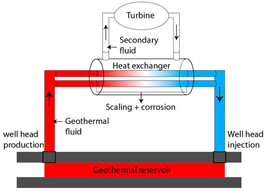
Figure 1. Schematic of a binary geothermal plant with a shell-and-tube type heat exchanger.
2.2. Types of Heat Exchangers
The most common heat exchanger design used in geothermal power plants include:
-
Shell and Tube Heat Exchangers: Shell and tube heat exchangers are frequently used in geothermal power plants, especially in binary cycle and hybrid systems. They are known for their versatility and effectiveness in handling high-temperature and high-pressure geothermal fluids. In binary cycle power plants, these heat exchangers are used to transfer heat from the geothermal fluid to the secondary working fluid (e.g., isobutane or isopentane) to drive a turbine.
-
Plate Heat Exchangers: Plate heat exchangers offer compact designs and efficient heat transfer capabilities, making them suitable for transferring heat between the geothermal fluid and the secondary working fluid.
-
Ground Heat Exchangers: They are used in geothermal heat pumps. The heat exchanger is in direct contact with the ground and allows heat transfer with the thermal fluid cooling/heating the building. This type of heat exchanger is mostly used for domestic applications and will not be covered here.
The choice of heat exchanger type in a geothermal power plant depends on factors like the temperature and pressure of the geothermal fluid, the characteristics of the secondary working fluid in binary systems, and the overall plant design.
2.3. In-Service Degradation
Heat exchangers in geothermal power plants are exposed to harsh operating conditions, including high temperatures, pressure fluctuations, and the presence of corrosive substances in geothermal fluids. These conditions can lead to various degradation mechanisms over time. The main degradation mechanisms for heat exchangers in geothermal power plants include:
-
Corrosion: Corrosion occurs when the metal surfaces of heat exchanger components react with the corrosive constituents present in geothermal fluids leading to impairment of the metal. These corrosive constituents, such as hydrogen sulphide (H2S), CO2, and other acidic compounds, can deteriorate the heat exchanger’s metal surfaces, leading to thinning of the materials and potential leakage. Corrosion can be mitigated via material selection, coatings, and water treatment.
-
Scaling: Scaling occurs when minerals and solids dissolved in the geothermal fluid precipitate and form deposits on heat exchanger surfaces. Common scale-forming minerals include calcium carbonate, silica, and various metal sulphides. Scaling reduces heat transfer efficiency, increases energy consumption, and can lead to mechanical damage if left unchecked. Regular cleaning or anti-scaling treatments are necessary to mitigate scaling.
-
Fouling: Fouling involves the accumulation of organic or inorganic materials on the heat exchanger surfaces, which can reduce heat transfer efficiency. Organic fouling may include microbial growth or algae, while inorganic fouling can result from particulate matter suspended in the geothermal fluid. Periodic maintenance, cleaning, and filtration can help prevent fouling.
-
Erosion: Erosion occurs when high-velocity geothermal fluid, containing abrasive particles, impinges on heat exchanger surfaces. Over time, this can lead to material loss and reduced heat transfer efficiency. Proper design and material selection can mitigate erosion, but some degree of wear is expected in high-velocity flow areas.
-
Hydrogen Embrittlement: In some geothermal environments with high H2S content, hydrogen embrittlement can occur. Hydrogen can diffuse into the metal microstructure of heat exchanger components, making them brittle and susceptible to cracking and failure. Prudent material selection and control of hydrogen exposure are essential to prevent this type of degradation.
3. Corrosion in Geothermal Environments
Corrosion presents a critical challenge in geothermal plants due to the aggressive nature of geothermal fluids. These fluids typically contain highly corrosive ions like chloride (Cl−) and may contain dissolved gases such as H2S and CO2. Moreover, elevated temperatures and dynamic flow conditions can accelerate corrosion by facilitating the mass transport of corrosive species and corrosion products. Corrosion is a multifactorial phenomenon that is inherently challenging to predict. In corrosion scenarios, the decision often revolves around accepting generalized and predictable corrosion or minimizing corrosion rates by opting for corrosion-resistant alloys (CRAs). The latter, however, exposes the system to unpredictable localized attacks. The former typically involves the use of cost-effective carbon steel (CS), a preference when replacement costs are low and outweigh the use of more expensive CRAs. Replacement costs are closely tied to the corrosion rate or unexpected corrosion-related failure, making it essential to determine the type of corrosion susceptible to occurring in the geothermal system.
3.1. Uniform Corrosion
Uniform corrosion, also known as general corrosion, is characterized by a relatively even and consistent corrosion attack that affects the entire exposed surface of a metal component. This type of corrosion typically occurs when geothermal fluids directly interact with metal surfaces over an extended period. Corrosion rates are commonly quantified in millimeters per year (mm year−1). Uniform corrosion is preferred over localized corrosion due to its predictable nature, which can be factored into design considerations. In general, an acceptable corrosion rate falls below 0.3 mm year−1 [16][17]. However, even this corrosion rate can be considered fairly high as such high corrosion rates would require significant corrosion allowance. Estimating the corrosion rate is particularly crucial when uniform corrosion poses the primary threat.
Under conditions of active dissolution, where soluble corrosion products are continuously exposed to the metal, the corrosion rate depends on thermodynamic factors such as temperature and acidity/alkalinity (pH). The corrosion rate increases with rising temperature and decreasing pH. However, in practical scenarios, even uniform corrosion becomes complex due to the deposition of corrosion products on the metal surface. In geothermal applications, the corrosion rate is influenced by various factors, including fluid composition, temperature, pH, pressure, metal material, and fluid flow characteristics.
The influence of temperature on the corrosion rate of CS in geothermal environments is not straightforward and can vary based on specific conditions. Nikitasari et al. [18] and Huttenloch et al. [19] observed that the corrosion rate tends to increase with rising temperature and decreasing pH. However, the presence of protective corrosion product layers can mitigate corrosion if they are sufficiently dense and adherent. For instance, Huttenloch et al. [19] noted a reduction in the corrosion rate at 160 °C compared to 80 °C and attributed this to the formation of a denser carbonate corrosion product layer [19]. Similar observations of lower corrosion rates at higher temperatures were reported for API L80 steel [20][21], although explanations were not provided.
Mundhenk et al. [22] identified different corrosion mechanisms at various temperatures (80, 120, and 160 °C) for API P110 steel. Corrosion was uniform at 80 and 160 °C, with a corrosion rate an order of magnitude lower at 160 °C. At 120 °C, corrosion was more localized. The corrosion products identified at 80 °C consisted of a Fe3C network, retained from the original metal microstructure, and impregnated with porous FeCO3, offering limited corrosion protection. Above 160 °C, a more protective crystalline Fe-oxide film formed, further lowering the corrosion rate [23]. Aristia et al. [24] also observed a reduction in the corrosion rate at 150 °C compared to 70 °C, attributed to the formation of a dense crystalline FeCO3 layer. At 70 °C, the corrosion product formation included chukanovite (Fe2(OH)2CO3) and siderite (FeCO3), which are less dense and, therefore, less protective.
In the liquid phase, the flow rate of the fluid significantly affects the corrosion rate, with increasing flow rate correlating with higher corrosion rates [18]. However, in the vapor phase, temperature is the dominant factor and the impact of flow rate is negligible [19]. In the vapor phase, corrosion is primarily induced by the formation of carbonic acid in condensed water in the presence of CO2. The presence of oxygen can accelerate corrosion, particularly when introduced during maintenance operations [20].
3.2. Localised Corrosion
Unlike uniform corrosion, localized corrosion is highly unpredictable and characterized by a rapid rate of metal penetration that can lead to premature component failure. Only a small section of the material is affected, with two primary forms of localized corrosion: pitting and crevicing.
Pitting corrosion occurs when the protective oxide film or deposit layer is breached at a local point, exposing a small area of the metal to the corrosive environment. The exposed metal dissolves, creating a pit that serves as an anode relative to the surrounding protected outer surface. Pitting is an autocatalytic process, where pit growth creates conditions that further encourage pit development [25]. Detecting pitting corrosion is challenging as it often results in minimal weight loss, making it difficult to identify. The formation of a pit can have severe consequences for the structural integrity of a component, as it represents a stress concentration feature. Under specific conditions, stress and pitting can interact, leading to stress corrosion cracking (SCC). Typically, pitting is associated with alloys like stainless steel, Ni-alloys, and titanium alloys that rely on the formation of a protective oxide film for corrosion resistance. Pitting corrosion is a stochastic phenomenon linked to material defects (such as slip planes, grain boundaries, or inclusions), design issues, or environmental factors.
Crevicing differs from pitting in terms of its initiation mechanism, which originates from geometric considerations. Crevicing occurs in narrow, enclosed spaces on the metal surface. This type of corrosion is often characterized by accelerated metal loss within the crevice or gap, driven by differences in oxygen (aeration cell) concentration, pH, or other factors between the crevice and the surrounding environment [26]. Crevices can form due to poor component design or after the deposition of scale deposits. Localized corrosion is exacerbated by the presence of chemical species in the geothermal fluid that promote depassivation, such as Cl−, SO4−, and H+ (low pH) [27].
3.3. Mechanically Assisted Corrosion
Mechanically assisted corrosion refers to a phenomenon where corrosion processes are accelerated due to the influence of mechanical forces, usually tensile stress. This acceleration can take different forms depending on the nature of the mechanical load. When the mechanical load involves erosive forces, it is specifically termed erosion–corrosion. Conversely, when cyclic stress is a contributing factor, it is referred to as corrosion fatigue. In systems where passivation is a key element of corrosion protection, mechanically assisted corrosion processes are believed to disrupt the protective passive film, thereby increasing the corrosion rate. In erosion–corrosion scenarios, corrosion is expedited by the relative motion between the metallic surface and the corrosive medium. This medium can take various forms, including fluids carrying suspended solid particles and/or bubbles, steam, or combinations thereof. This relative motion continually removes the passive film or corrosion products, exposing fresh metal surfaces to the corrosive medium [28]. Consequently, areas with higher flow velocity experience a faster rate of erosion–corrosion. In geothermal systems, erosion–corrosion occurs in high-velocity and pressure fluid conditions and may lead to distortion of heat exchanger tube shapes [12].
Corrosion fatigue, on the other hand, results from the combined effect of alternating stresses and exposure to a corrosive environment [29][30]. This mechanism is particularly significant in passivating metals, where stresses can facilitate pit formation. These pits act as stress concentrators and initiation sites for fatigue cracks. Corrosion fatigue typically leads to brittle fractures through the growth of transgranular cracks. In geothermal systems, sources of cyclic stress contributing to corrosion fatigue have been identified, such as steam turbine vibrations and the periodic expansion/contraction of pipelines due to fluctuations in the temperature of the transported steam or fluid [10].
3.4. Hydrogen and Hydrogen Related Stress Corrosion Cracking
Hydrogen cracking is a phenomenon characterized by the diffusion of hydrogen atoms into the crystalline lattice structure of a metal, causing subsequent damage. Hydrogen can originate from various sources, including manufacturing processes or as by-products of corrosion reactions (such as cathodic reactions involving reduction in water) [31][32]. These hydrogen atoms when inside the metal can recombine to form molecular hydrogen (H2), which occupies a significantly larger volume than the atoms. This localized accumulation of hydrogen can create areas of elevated stress within the metal, potentially initiating and propagating cracks. Under the influence of tensile stress, these cracks have the potential to propagate, ultimately leading to the brittle failure of the material. In the presence of certain substances, such as hydrogen sulphide (H2S) or arsenic compounds, the hydrogen cracking process accelerates. These substances act as recombination poison and delay the formation of molecular hydrogen (H2), extending the residence time of atomic hydrogen on the metal surface thus increasing the probability of atomic hydrogen ingress in the metal. When this phenomenon occurs in an environment saturated with H2S, followed by cracking of the metal in the presence of stress, it is commonly referred to as Sulphide Stress Cracking (SSC).
SCC shares similarities with hydrogen cracking with both qualifying as environmentally assisted cracking (EAC). The key difference is that corrosion serves as the catalyst for crack initiation and propagation in SCC. SCC requires both a corrosive environment and sustained surface tensile stress on a susceptible material [33][34]. Crack initiation can result from various factors, including the formation of a pit or crevice, microstructural defects, or high local stress. Once the crack initiates, the combined effects of the corrosive environment and stress accelerate crack propagation. Hydrogen cracking and SCC can occur simultaneously, further enhancing crack propagation.
References
- El Haj Assad, M.; Bani-Hani, E.; Khalil, M. Performance of geothermal power plants (single, dual, and binary) to compensate for LHC-CERN power consumption: Comparative study. Geotherm. Energy 2017, 5, 17.
- van der Zwaan, B.; Dalla Longa, F. Integrated assessment projections for global geothermal energy use. Geothermics 2019, 82, 203–211.
- Lukawski, M.; Tester, J.W.; Bendall, B.; Goldstein, B.; Hiriart, G.; Gutierrez-Negrin, L.; Bertani, R.; Bromley, C.; Huenges, E.; Ragnarsson, A.; et al. Geothermal Energy, Nature, Use, and Expectations. In Power Stations Using Locally Available Energy Sources: A Volume in the Encyclopedia of Sustainability Science and Technology Series, 2nd ed.; Bronicki, L.Y., Ed.; Springer New York: New York, NY, USA, 2018; pp. 35–46.
- IEA. Net Zero by 2050—A Roadmap for the Global Energy Sector; IEA: Paris, France, 2021.
- Bertani, R. Geothermal power generation in the world 2010–2014 update report. Geothermics 2016, 60, 31–43.
- Tester, J.W.; Anderson, B.J.; Batchelor, A.S.; Blackwell, D.D.; DiPippo, R.; Drake, E.M.; Garnish, J.; Livesay, B.; Moore, M.; Nichols, K. The future of geothermal energy. Mass. Inst. Technol. 2006, 358, 1–3.
- Shannon, D.W. Economic Impact of Corrosion and Scaling Problems in Geothermal Energy Systems; Battelle Pacific Northwest Labs.: Richland, WA, USA, 1975.
- Tardiff, G. Using Salton Sea Geothermal Brines for Electrical Power: A Review of Progress in Chemistry and Materials Technology, 1976 Status. 1977. Available online: https://www.osti.gov/biblio/7302949 (accessed on 9 August 2023).
- Karlsdottir, S.N.; Pálsson, H.; Manadao Bravo, A., Jr.; Stefánsson, A.; Boakye, G.O. Corrosion Testing of Coatings in Simulated ORC Geothermal Heat Exchanger Environment. In Proceedings of the AMPP Annual Conference + Expo, Denver, CO, USA, 19–23 March 2023; p. AMPP-2023-19444.
- Yang, J.K.; Li, C.; Pan, Y.; Huang, H. The Failure Mechanism of the 316 SS Heat Exchanger Tube in the Geothermal Water Environment. Materials 2022, 15, 8103.
- Ledésert, B.A.; Hébert, R.L.; Mouchot, J.; Bosia, C.; Ravier, G.; Seibel, O.; Dalmais, É.; Ledésert, M.; Trullenque, G.; Sengelen, X.; et al. Scaling in a Geothermal Heat Exchanger at Soultz-Sous-Forêts (Upper Rhine Graben, France): A XRD and SEM-EDS Characterization of Sulfide Precipitates. Geosciences 2021, 11, 271.
- Morake, J.B.; Mutua, J.M.; Ruthandi, M.M.; Olakanmi, E.O.; Botes, A. Failure analysis of corroded heat exchanger CuNi tubes from a geothermal plant. Eng. Fail. Anal. 2023, 153, 107543.
- Facca, G. Future of geothermal energy. Geotherm. Energy Mag. 1973, 1, 372.
- DiPippo, R. Geothermal Power Plants: Principles, Applications, Case Studies and Environmental Impact; Butterworth-Heinemann: Oxford, UK, 2012.
- Hijriawan, M.; Pambudi, N.A.; Biddinika, M.K.; Wijayanto, D.S.; Kuncoro, I.W.; Rudiyanto, B.; Wibowo, K.M. Organic Rankine Cycle (ORC) in geothermal power plants. J. Phys. Conf. Ser. 2019, 1402, 044064.
- Bäßler, R.; Keserovic, A.; Sobetzki, J.; Sarmiento Klapper, H.; Dimper, M. Materials evaluation for geothermal applications in different geothermal waters. In Proceedings of the World Geothermal Congress 2015, Melbourne, Australia, 19 April 2015; pp. 27011–27017.
- Huttenloch, P.; Zorn, R.; Makni, L.; Steger, H.; Schilling, F.R.; Hater, W. Inhibitor performance on carbon steel in the geothermal environment of the Upper Rhine graben (Central Europe)—A laboratory study. Geothermics 2019, 81, 198–208.
- Nikitasari, A.; Royani, A.; Priyotomo, G.; Sundjono, S. The effect of flow rate and temperature on corrosion rate of carbon steel pipe in condensate solution from geothermal power plant. Acta Metallurgica Slovaca 2021, 27, 133–138.
- Huttenloch, P.; Zorn, R.; Steger, H.; Schilling, F.; Hater, W. Performance of corrosion inhibitors on carbon steel in the geothermal environment of the Upper Rhine Graben (URG) depending on inhibitor concentration, temperature and hydrodynamic conditions-A laboratory study. Geothermics 2021, 92, 102047.
- Vallejo Vitaller, A.; Angst, U.M.; Elsener, B. Laboratory tests simulating corrosion in geothermal power plants: Influence of service conditions. Geotherm. Energy 2020, 8, 9.
- Vitaller, A.V.; Angst, U.M.; Elsener, B. Corrosion Behaviour of L80 Steel Grade in Geothermal Power Plants in Switzerland. Metals 2019, 9, 331.
- Mundhenk, N.; Knauss, K.G.; Bandaru, S.R.S.; Wonneberger, R.; Devine, T.M. Corrosion of carbon steel and the passivating properties of corrosion films formed under high-PT geothermal conditions. Sci. Total Environ. 2019, 677, 307–314.
- Mundhenk, N.; Carrero, S.; Knauss, K.G.; Wonneberger, R.; Undisz, A.; Wu, Y. Kinetic and thermodynamic analysis of high-temperature CO2 corrosion of carbon steel in simulated geothermal NaCl fluids. Corros. Sci. 2020, 171, 108597.
- Aristia, G.A.G.; Hoa, L.Q.; Bäßler, R. Corrosion of Carbon Steel in Artificial Geothermal Brine: Influence of Carbon Dioxide at 70 °C and 150 °C. Materials 2019, 12, 3801.
- Trethewey, K.R.; Chamberlain, J. Corrosion for Science and Engineering. 1995. Available online: https://www.osti.gov/biblio/378108 (accessed on 9 August 2023).
- Scully, J.C. Fundamentals of Corrosion. 1975. Available online: https://www.osti.gov/biblio/7116490 (accessed on 9 August 2023).
- Frankel, G.S. Pitting Corrosion of Metals: A Review of the Critical Factors. J. Electrochem. Soc. 1998, 145, 2186.
- Brownlie, F.; Hodgkiess, T.; Pearson, A.; Galloway, A.M. A study on the erosion-corrosion behaviour of engineering materials used in the geothermal industry. Wear 2021, 477, 203821.
- Wolf, M.; Afanasiev, R.; Böllinghaus, T.; Pfennig, A. Investigation of Corrosion Fatigue of Duplex Steel X2CrNiMoN22-5 3 Exposed to a Geothermal Environment under Different Electrochemical Conditions and Load Types. Energy Procedia 2017, 114, 5337–5345.
- Pfennig, A.; Wiegand, R.; Wolf, M.; Bork, C.P. Corrosion and corrosion fatigue of AISI 420C (X46Cr13) at 60 °C in CO2-saturated artificial geothermal brine. Corros. Sci. 2013, 68, 134–143.
- Lichti, K.A.; Firth, D.M.; Karstensen, A.D. Hydrogen Induced Cracking of Low Strength Steels in Geothermal Fluids. In Proceedings of the World Geothermal Congress 2005, Antalya, Turkey, 24–29 April 2005; pp. 24–29.
- Karlsdottir, S.N.; Thorbjornsson, I.O. Hydrogen Embrittlement And Corrosion In High Temperature Geothermal Well. In Proceedings of the Corrosion 2012, Salt Lake City, UT, USA, 11–15 March 2012; p. NACE-2012-1467.
- Hurley, M.F.; Olson, C.R.; Ward, L.J.; Jaques, B.J.; Johnson, K.A.; Gunnerson, J.K.; Butt, D.P. Transgranular stress corrosion cracking of 304L stainless steel pipe clamps in direct use geothermal water heating applications. Eng. Fail. Anal. 2013, 33, 336–346.
- Qi, W.; Gao, Q.; Zhao, Y.; Zhang, T.; Wang, F. Insight into the stress corrosion cracking of HP-13Cr stainless steel in the aggressive geothermal environment. Corros. Sci. 2021, 190, 109699.
More
Information
Contributors
MDPI registered users' name will be linked to their SciProfiles pages. To register with us, please refer to https://encyclopedia.pub/register
:
View Times:
2.0K
Revisions:
2 times
(View History)
Update Date:
31 Oct 2023
Table of Contents


Notice
You are not a member of the advisory board for this topic. If you want to update advisory board member profile, please contact office@encyclopedia.pub.
OK
Confirm
Only members of the Encyclopedia advisory board for this topic are allowed to note entries. Would you like to become an advisory board member of the Encyclopedia?
Yes
No
${ textCharacter }/${ maxCharacter }
Submit
Cancel
Back
Comments
${ item }
|
${ item.createdUser.fullName }
${ item.createdAt }
${ item.vote }
${ item.reply }
Delete
${ reply.createdUser.fullName }
${ reply.createdAt }
${ reply.vote }
Delete
There is no reply to this comment~
${ item.replyTextCharacter }/${ item.replyMaxCharacter }
Submit
Cancel
More
No more~
There is no comment~
${ textCharacter }/${ maxCharacter }
Submit
Cancel
${ selectedItem.replyTextCharacter }/${ selectedItem.replyMaxCharacter }
Submit
Cancel
Confirm
Are you sure to Delete?
Yes
No