Submitted Successfully!
To reward your contribution, here is a gift for you: A free trial for our video production service.
Thank you for your contribution! You can also upload a video entry or images related to this topic.
Version Summary Created by Modification Content Size Created at Operation
1 -- 4210 2023-10-18 11:42:53 |
2 Reference format revised. Meta information modification 4210 2023-10-19 02:42:05 | |
3 Main text format revised. Meta information modification 4210 2023-10-19 02:42:55 |

Video Upload Options

Do you have a full video?

Confirm

Are you sure to Delete?
Cite
If you have any further questions, please contact Encyclopedia Editorial Office.
Jeremias, F.T.; Cripps, J. Laboratory Testing and Classification of Mudrocks. Encyclopedia. Available online: https://encyclopedia.pub/entry/50453 (accessed on 19 May 2024).
Jeremias FT, Cripps J. Laboratory Testing and Classification of Mudrocks. Encyclopedia. Available at: https://encyclopedia.pub/entry/50453. Accessed May 19, 2024.
Jeremias, Filipe Telmo, John Cripps. "Laboratory Testing and Classification of Mudrocks" Encyclopedia, https://encyclopedia.pub/entry/50453 (accessed May 19, 2024).
Jeremias, F.T., & Cripps, J. (2023, October 18). Laboratory Testing and Classification of Mudrocks. In Encyclopedia. https://encyclopedia.pub/entry/50453
Jeremias, Filipe Telmo and John Cripps. "Laboratory Testing and Classification of Mudrocks." Encyclopedia. Web. 18 October, 2023.
Laboratory Testing and Classification of Mudrocks
Edit

Mudrocks are fine-grained clay-rich rocks that comprise different lithotypes forming more than 60% of all sedimentary rocks, and thus, they occur frequently in engineering projects either as natural ground or as made ground. These rocks may display a range of engineering behaviours controlled mostly by their composition and structural features. Due to rapid breakdown and susceptibility to volume changes, they may cause problems both during and after construction. Research into the susceptibility of mudrocks to breakdown aims to predict problematic behaviour and provide guidance for avoiding or mitigating these effects. Low-durability materials that disintegrate during sampling and testing can be especially difficult to assess. 

mudrocks laboratory tests geological classifications engineering geological classifications durability

1. Introduction

In spite of constituting more than 60% of all sedimentary rocks [1], mudrocks have been less studied than other sedimentary rock types, such as sandstones or limestones [2]. This is attributed to them being encountered in a weathered condition at surface exposures, and furthermore, they are fine-grained materials with a complex composition that needs specific laboratory analysis for their determination [2][3][4].
The term mudrock is used to define fine-grained sedimentary rocks constituted by more than 50% of siliciclastic grains less than 63 μm in size [5] that are typically composed of over 90% clay minerals, quartz, and feldspar. Often clay minerals will make up about 60% of the total. Carbonates may occur as grains or cement; other non-detrital minor constituents, including pyrite and organic matter, and iron-bearing compounds that are important as pigmenting agents [1][4][5] may also be present.
Fabric and grain size are the most important textural features of mudrocks. Fabric characterizes the geometric arrangement of the particles, which is influenced by the environmental conditions prevailing during sedimentation and by post-depositional loading-unloading history. A common fabric type consisting of clay flakes arranged parallel to bedding (fabric lamination) imparts fissility to the rock. This feature, which may be enhanced by weathering processes, results in the tendency of the material to split along weak surfaces parallel to the stratification. The percentages of clay size (2 μm) and silt size (63 μm) fractions present in mudrocks constitute the criteria to differentiate the mudrock lithotypes, such as claystone, mudstone, and siltstone (see Figure 1) [6].
Figure 1. Lundegard and Samuels’s classification of mudrock.
Stratification is a common structural feature of mudrocks which is termed bedding or laminae, where the later applies for layering thinner than 10 mm [1]. Although there is no generally accepted geological classification of mudrock, stratification and grain size are the two parameters most widely adopted in the schemes used.
Several genetic factors, including composition, induration degree, and post-depositional diagenetic changes, strongly influence the engineering properties of mudrock, particularly plasticity, strength, deformability, swelling, and durability/slaking behaviour [7][8]. The increase in burial depth and the accompanying enhancement of diagenetic bonding produce a stronger, more brittle, and more durable material. On the other hand, the removal of overburden and weathering processes results in the release of strain energy and the weakening of diagenetic bonding.
The engineering properties of mudrocks can be determined by performing appropriate laboratory tests, according to whether the material displays rock- or soil-like characteristics. However, due to the sensitivity of clay-rich materials to changes in stress and moisture content, the processes of sampling and preparation for testing may have a serious impact on the results these reveal. A particular issue is that tests may only be performed on the more durable materials, which will impart an over-estimated view of mudrock geotechnical performance in civil engineering works [9].

2. Laboratory Testing of Mudrocks

2.1. Mineralogical, Textural, and Chemical Characterization

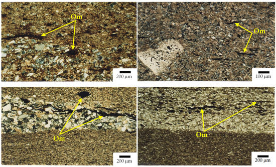
2.1.1. Polarizing Microscopy

Polarizing microscopy may be used to study the mineralogy and texture of sand-sized and silt-sized constituents of mudrocks, including features such as cross-bedding, particle shape, segregation and orientations, micro-lamination, and cementation/bonding. Figure 2 shows microphotographs in crossed polars of mudrocks from Abadia Beds (Lower Kimmeridgian—Portugal). Crossed polars refer to the use of polarized light to assist in the identification of the different mineral constituents.
Figure 2. Massive siltstone (upper left), massive mudstone (upper right), micro-laminated siltstone (lower left), micro-laminated mudstone (lower right), from Abadia Beds, Lower Kimmeridgian, Portugal; (Om) organic matter.
The process of preparation of the slide for microscope examination entails cutting a thin slice of the rock, which is then polished using fine-grinding carborundum power and attached with resin to a glass slide. The thickness of the slice is then reduced to 30 μm by grinding the surface; thus, only rocks can be examined using this technique. Weak rocks can be stabilized by casting them into a resin block before the slice is cut. This whole process is technically demanding, and the use of the microscope for the identification and description of textural features is a skilled operation. As the identification of the mineral components depends on the transmission of light through the grain, due to their small size, it is not possible to discern individual clay grains in thin sections.
Figure 2 shows both massive and laminated siltstone and mudstone. Massive mudrocks (upper microphotographs) are partly cemented and show partly oriented fabric with detrital and matrix carbonates. Laminated mudrocks (lower microphotographs) show coarser and fine lamina. The former consists mainly of rounded and sub-angular grains of quartz (white and grey), some fragments, and inter-granular cementing calcite (brightly coloured) with strands and pieces of organic material (black). The finer parts contain small grains of calcite and quartz, and there may be clay minerals, intergranular calcite cement, and fragments of organic matter. Much of the ground mass of the finer parts of the slide is too small for the grains to be identified. These mudrocks would easily split along the silty laminae due to the presence of weak organic material; however, the resulting fragments would probably be strong as the calcite cement would resist particle separation.

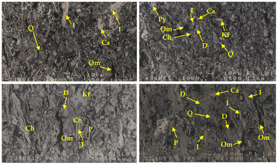
2.1.2. Scanning Electron Microscopy

Both mineralogical and textural aspects of mudrocks may be studied by scanning electron microscopy (SEM). Secondary electron images (SEI) are used to study textural features, including fabric, shape, and size of the grains and pore space geometry. Backscattered electron (BEI) images are useful in distinguishing minerals phases as they provide atomic number contrast. The mineralogy of grains can be identified by their visual appearance or the chemical composition of grains which may be determined by an energy-dispersive X-ray analysis system (EDS) joined to SEM. The data obtained allow the role of a specific mineral phase and/or the association between mineral phases to be determined within the mudrock fabric being analysed. As the area viewed is less than 1 mm across, it is not possible to identify textural features using SEM. Figure 3 shows BEI images with the identification of minerals phases present in both siltstones and mudstone samples from Abadia Beds (Lower Kimmeridgian—Portugal).
Figure 3. Massive siltstone (upper left), massive mudstone (upper right), micro-laminated siltstone (lower left), micro-laminated mudstone (lower right), from Abadia Beds, Lower Kimmeridgian, Portugal; (Q) quartz, (Fk) K-feldspar, (P) plagioclase, (Ca) calcite, (D) dolomite, (I) illite/mica, (Ch) chlorite, (Py) pyrite and (Om) organic matter.

2.1.3. X-ray Diffraction

Although both optical and SE microscopy may facilitate the identification of the mineralogical composition of mudrocks, neither method provides a quantitative analysis. The mineral phases of mudrocks are usually determined by X-ray diffraction, which can return both qualitative and semi-quantitative determinations. The soil or rock is ground to a fine powder and mounted randomly oriented on a slide that is exposed to a beam of X-rays. The spectrum of X-rays reflected from the minerals in the sample is used to identify the different mineral phases present in the rock. Identification of clay minerals is assisted by subjecting the sample to pre-treatments, including separation of the <2 μm fraction, glycolation, heating, and creating particle alignment by depositing a slurry on to a slide.
X-ray diffraction requires the use of sophisticated analytical hardware, specialised software to interpret the X-ray spectrum by an adequately trained operator. The equipment must be calibrated to perform quantitative analyses.

2.1.4. Porosimetry

Mercury intrusion porosimetry (MIP) and gas intrusion (BET) are used to determine effective porosity, pore distribution, surface porosity, and particle size of small intact samples of mudrocks. The characterization of those microtextural features is important as they are closely related to breakdown processes developed in mudrocks. Specialised equipment is used for the determinations.

2.1.5. Chemical Analyses

Several techniques, including wet chemical, Inductively Coupled Plasma Atomic Absorption Spectrometry (ICP-AAS), Atomic Absorption (AA), or X-ray Fluorescence (XRF) methods, may be used to determine bulk chemical analysis for both major and trace elements present in mudrocks (see BS1377-3:2018, [10]). Among those, XRF in which a powdered sample of the rock or soil is analysed, is a rapid procedure providing analysis of most mudrock components. However, chemical data have limited value in weathering assessment as only small changes in chemical composition accompany physical weathering processes if these predominate.
The amount of pyrite present in a mudrock sample can be determined by determining the total sulphur content by High-Temperature Combustion and then treating a sample with acid to remove any acid-soluble sulphur and analysing the resulting solution using ICP atomic emission spectroscopy or other means. In most geological materials, gypsum is the acid-soluble sulphur compound and pyrite is the only acid-insoluble sulphur compound, so the amount of pyrite can be calculated from the difference between total sulphur and acid-soluble sulphur.

2.2. Identification Test

2.2.1. Density and Porosity

Density and total and effective porosity may be determined by several testing procedures provided by the International Society for Rock Mechanics (ISRM) [11]. Alternative methods, such as mercury porosimetry, are used on samples that disintegrate under vacuum saturation.

2.2.2. Natural Water Content

The natural water content gives valuable information concerning the presence of hydrophilic compounds in rock, particularly clay minerals. Thus clay-rich mudrocks, especially those containing swelling species, have relatively high natural water contents. Water absorption and water adsorption contents are, respectively, determined by conducting immersion tests and exposure of samples of rock fragments to specific moisture conditions [11].

2.2.3. Particle Size and Atterberg Limits

Prior disaggregation of the material is necessary for the determination of particle size distribution [12] and Atterberg limits [13]. Methods of disaggregation include alternate wetting and drying, the use of acids or chemical dispersing agents, and mechanical crushing. However, inter-particle bonding in mudrocks may prevent the disaggregation of the material into individual particles, in which case the values obtained in these tests are highly dependent on the effectiveness of the disaggregation procedure.

2.2.4. Methylene Blue Adsorption

The methylene blue adsorption spot test may be used to evaluate the hydrophilic surface characteristics of the clay minerals and, thus, their capacity to retain water. Methylene blue is not adsorbed by inert minerals and thus may be used as a routine test to assess the swelling clay component in a powdered rock sample [14].

2.3. Strength and Deformability

2.3.1. Uniaxial Compressive Strength Tests

Uniaxial compressive strength procedures are given by ISRM [15] and ASTM [16]. The preparation of cylindrical or prismatic specimens for the test comprises the major drawback of this test in mudrock, especially material containing laminations that hamper the preparation of specimens with dimensions suitable for the test. The tests also entail drying the specimens, which may cause them to become damaged.

2.3.2. Tensile Strength Tests

Testing procedures for tensile strength are given in ISRM [17], but preparing samples and applying tensile forces to specimens are very challenging, so often diametral compression (Brazilian) tests are carried out. However, particularly on massive mudrocks, as diametral testing pre-determines the specimen failure surface, they give higher values than direct tensile strength tests.

2.3.3. Point Load Test

The point load strength test procedure is described in ISRM [18]. Although the damage to specimens is caused by coring or cutting equipment, the test is most suitable for testing indurated strong mudrock types. It is not appropriate for weak or weathered materials. Poor results are obtained for irregular block mudrock samples with an axial distance smaller than 25 mm. Equidimensional lumps tested with loading direction perpendicular to stratification or weakness planes provide the most consistent results. However, for mudrock strength, anisotropy assessments with loading directions normal and parallel to bedding must be carried out.

2.3.4. Schmidt Rebound Test-Hammer

The testing procedures for the Schmidt rebound test hammer are given by ISRM [19]. This equipment is mostly used for field testing of rock outcrops, but it is also used for laboratory testing on core and/or block samples. Determinations of rebound number using an N19 Schmidt rebound test hammer for UK mudstones are provided by Carter and Sneddon [20].

2.3.5. National Coal Board Cone Indenter (NCB)

The National Coal Board (NCB) cone intender [21] was developed to determine the strength of rock chips not greater than 12 × 12 × 6 mm in size, where the testing procedures are provided by the National Coal Board, UK [21]. It is a portable device that does not require elaborate specimen preparation. It is very suitable for testing thinly bedded or fractured mudrock fragments that would break up during the preparation of specimens for uniaxial compression tests. In the test, a steel cone is driven against the rock fragment until the deflection values of the steel beam reach 0.635 mm (standard test) or 0.23 mm (soft rock test).

2.4. Swelling

2.4.1. Swelling Strain

Axial swelling strain tests on radially confined remoulded specimens performed following the National Laboratory for Civil Engineering (LNEC) test standard E- 200 [22] provide data about the swelling of the mineralogical constituents of the material in the presence of water. The apparatus is illustrated in Figure 4a, where the sample consists of two 15 mm thick compacted layers of dry disaggregated material passing a #40 ASTM (425 μm) sieve. The compaction is performed using a specific plunger applying a force of 0.5 MPa. A micrometer dial gauge reading of 0.01 mm is used to record swelling strain resulting from immersion in water over a test time of 48 h.
Figure 4. Diagrammatic illustrations of the apparatus used to measure swelling strain [23]: (a) on radially confined remoulded specimens; (b) on rock specimens.
Uniaxial and triaxial swelling strain test procedures for intact rock specimens using the apparatus shown in Figure 4b are given by ISRM [11]. One of the orthogonal axes is perpendicular to the bedding or parting in the rock. The test specimens consist of pre-cut cubes of approximately 30 mm side lengths, and they are mounted with the z-axis normal to the bedding. Micrometer dial gauges reading to 0.001 mm record swelling strain due to immersion in water during a standard test time of 48 h or until swelling has ceased. Problems arise with cutting the cubes in weak and low-durability materials.

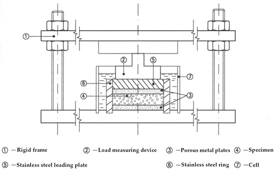
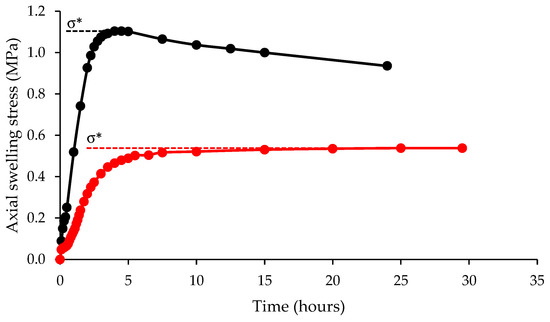
2.4.2. Swelling Stress

Swelling stress–strain test procedures are provided by ISRM [24], which require that the applied force is increased during the test to prevent the specimen from increasing in volume during the test. The apparatus described by Jeremias [23] consists of a rigid frame and an electrical load cell, as shown in Figure 5. The swelling stress developed under conditions of zero volume change on Portuguese mudrock samples of Cretaceous age is shown in Figure 6 [25].
Figure 5. Apparatus for measuring the axial swelling stress of an undisturbed radially confined rock specimen [23].
Figure 6. Axial swelling pressure versus time plots of Cretaceous Portuguese mudrocks measured perpendicular (black) and parallel (red) to bedding [25]. σ∗ —Maximum axial swelling stress.

2.5. Durability

2.5.1. Ageing Tests

Natural exposure and ageing tests provide means of mudrock durability assessment. Details of the long-term disintegration behaviour of mudrocks subjected to natural exposure tests are given by Shakoor and Gautam [26]. In ageing tests, a specific weathering process is reproduced, of which the most common are cyclic wetting and drying, freezing and thawing, and soundness tests. Although these tests are used in research studies, they are very time-consuming and not commonly used in routine investigations.

2.5.2. Slake Durability Test

Mudrock durability assessment in routine studies is usually based on slaking due to cyclic wetting and drying and mechanical disturbance evaluated using the slake durability test apparatus proposed by Franklin and Chandra [27]. This test was further recommended by ISRM [11] and standardized by ASTM [28]. The two-cycle slaking durability index (Id2) has been adopted in several classification schemes for mudrock durability assessment. For the test, 10 equidimensional dried rock lumps, each 40–60 g mass, are placed in a cylindrical drum formed out of 2 mm mesh that is rotated on a horizontal axis while partly submerged in a water bath. The amount of sample retained in the drum after 200 rotations is collected, dried, and expressed as a percentage of the original dry mass of the sample.

2.5.3. Static Slake Test

The static slake test consists of one cycle in which an oven-dried 40–50 mm sized cube of rock in which one face is perpendicular to the bedding, is immersed in water, and its behaviour is observed at specific times over a period of 24 h.
Several classification schemes have been proposed [29][30][31][32] to categorise the slaking behaviour of mudrocks. Santi [33] linked static slake categories to the types of slaking observed and proposed a six-category classification providing a standard visual basis for distinguishing between degrees of chip or fracture formation. Accordingly, category 1 refers to degradation to a mud-like consistency, and categories 2 and 3, respectively, describe the formation of flakes and chips. Categories 4 and 5 describe the formation of fractures and slabs, and category 6 is applied when no reaction is observed.

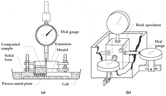
2.6. Compaction Tests

In this context, compaction tests are used to study the change of grading between uncompacted and compacted material, which reflects the breakdown of the particles during the compaction process. Several procedures have been proposed for this mudrock degradability assessment, but the test given by NF P94-066 [34] is one of the most used. In this test, degradability is expressed as the ratio between D10 determined in the initial grading curve for the sample and of D10 obtained in the grading curve after sample compaction with one hundred blows with a standard Proctor hammer using a CBR mould. Ratios higher than 7 express materials are prone to breakdown.

3. Mudrock Classifications

3.1. Geological Classifications

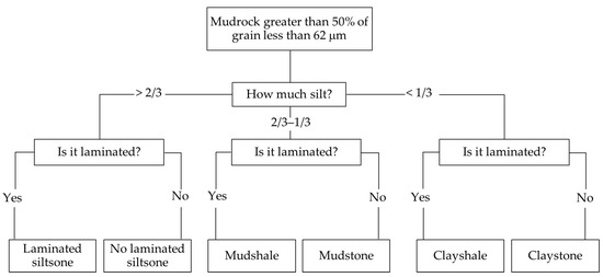
The descriptive schemes used for mudrock geological classification are based on features with some genetic significance. Table 1 shows the guidance given by Czerewko and Cripps [35] for the description of mudrock key features. Colour, mineralogy, fossil content, fracture type, and induration state are descriptive modifiers that complement the root names for a better mudrock characterization.

Table 1. Guide to the description of mudrock features [35].
Attribute Descriptive Adjectives
Induration Enables decision on description as soil or rock. If resistant to slaking in water and hard, it is rock; if susceptible to slaking in water, deformable, and ‘earthy consistency, it is soil. Strength depends on moisture state; dry sediment is stronger than wet, and rock strength varies with moisture content; sampling may impair strength.
Strength Strength is designated based on the degree of induration. For soil, use field consistency values based on manual assessment, e.g., stiff; when shear strength measurements are made, use strength terms, e.g., high strength. For rock, a definition based principally on manual field assessment using geological hammer and knife may be confirmed with UCS measurement: indurated mudrocks range from extremely weak to medium strong; metamudrocks are stronger depending on weathering.
Structure Standard terms for beds, laminae, and parting are provided by Potter et al. [1]. Include description of lithology and textural inter-relationship, as complex features may be present with structured strata such as ‘thin beds of cross bedded’ mudstone.
Colour Use Munsell colour chart for consistency. Important for correlation; likely environment of formation and indication of likely behaviour of material, i.e., red colour—likely formation under oxidizing continental environment. Most important to mudrocks is relationship between colour on the Fe3+/Fe2+ ratio. A decrease in this ratio gives an increase in colour from red → green → grey (more Fe2+ indicates the presence of pyrite). Organic carbon controls colour: <0.2–0.3%C = light-grey to olive grey; 0.3–0.5%C = mid-grey; >0.5%C = dark-grey to black.
Accessory minerals Calcareous (slightly to very, based on level of effervescence when assessed with HCl, carbonaceous, dolomitic, ferruginous, glauconitic, gypsiferous, pyritic, micaceous, sideritic, phosphatic.
Rock name See classification of Figure 1.
Additional information Presence of fossils—record type (generic such as bivalve and retain for identification), abundance, condition, orientation. Inclusions—nodules (with mineral type and details); gravel, sand, silt partings or pockets, etc.
State of weathering Alteration seen as distinct discoloration, significant strength reduction to discontinuities, and presence of lithorelicts (note orientation).
Fractures Use ISO 14689:2017 standard terms and procedures [36]. For rock supplements with details such as nature of fragmentation, e.g., conchoidal, hackly, brittle, splintery, slabby, fissile.
Full engineering descriptions of the intrinsic condition and mass properties using descriptive adjectives provided in ISO standards [36][37][38].
Texture (grain size) and structure are the most helpful geological properties for describing and classifying mudrocks. Texture describes the relationships between the silt- and clay-sized fractions in mudrock. The structure is characterized by fissility and stratification. Fissility is defined as the character of the rock being prone to separate along lamination or bedding planes. Stratification reflects the vertical changes in composition, colour, and/or fabric that occur in sedimentary sequences. In laminations, this occurs at a spacing of less than 10 mm, whereas bedding is thicker than this. Weathering processes tend greatly to enhance fissility such that some mudrocks are prone to split into very thin layers along planar weakness surfaces. 
Stratification as either laminae (<10 mm) or bedding (>10 mm) is a natural classification factor to distinguish between bedded massive mudrocks and laminated mudrocks [1]

3.2. Engineering Geological Classifications

Attempts at engineering definitions of mudrock have been proposed by several authors [39][40][41][42][43][44][45][46], and a main concern in the classification of such materials is the division between soil and rock. The distinction between ‘compaction shales’, which are consolidated muddy sediments without intergranular cement, and ‘cemented shales’, which contain intergranular cement, was proposed by Mead [41] and followed by Underwood’s classification [42].
The latter was the first to distinguish the control of soil-like and rock-like properties on mudrock breakdown behaviour. Additionally, as pointed out by Cripps and Taylor [7], induration, stress history, and weathering are factors that strongly influence engineering properties. Another approach to defining a soil/rock boundary is based on the strength characteristics of the materials [39][40][43][44][45].
However, it is recognized that there is no specific strength limit that is widely accepted as a soil/rock boundary, and there is a lack of standardization of the definition of weak rock, as different institutions and researchers suggested different UCS values [35][39][40][44][45], and whether loading results in brittle or plastic deformation depends on the confining conditions and the rate of loading.
The increase of civil engineering works dealing with mudrocks as natural ground on construction and ground engineering sites and as made ground, fill, and construction material promoted the development of several classification schemes based on mechanical and engineering properties. Such classifications aim to provide criteria to deal with mudrocks in design studies and in the organization and management of the construction process.
Erguler and Shakoor [47] proposed a mudrock durability classification based on the disintegration ratio (DR) and second-cycle slake durability index (Id2) following the six classes defined in Gamble’s classification. Accordingly, the six categories of the Erguler and Shakoor’s classification are as follows: very low (Id2 0–30%—DR 0.00–0.19), low (Id2 30–60%—DR 0.20–0.49), medium (Id2 60–85%—DR 0.50–0.78), medium-high (Id2 85–95%—DR 0.79–0.91), high (Id2 95–98%—DR 0.92–0.95) and very high (Id2 98–100%—DR 0.96–1.00).

4. Conclusions

Because of their small grain size, composition, and structural features and the possibility of mudrocks causing problems in engineering applications, a number of special techniques for investigation and assessment must be deployed. Guidance for both research studies and for routine investigation works for engineering concerning key features of mudrocks is given in standards and in the literature. Unfortunately, detailed characterization of mudrocks involving mineralogical, textural, and geotechnical determinations often entails the use of specialist investigations that are costly and time-consuming to perform. An alternative, more practical approach is to employ a selection of suitable index tests to distinguish problematic from non-problematic materials and to derive suitable values for key geotechnical design parameters. This methodology is particularly appropriate for the reconnaissance phase of projects, and suitable schemes for this are proposed by Jeremias [23], Czerewko and Cripps [29], Erguler and Shakoor [47] and Erguler and Ulusay [48]. However, these classification schemes were developed using data derived from rocks collected on particular geological formations (Portugal, the UK, the US, and Turkey). Therefore, for their general application, further testing involving other geological formations is needed. Furthermore, the particular problems liable to occur with a mudrock in the proposed engineering situation must be recognized and allowed to direct the investigation to avoid or mitigate any potential problems.
Siltstones, mudstones, and claystones are differentiated based on texture (grain size), and whether the material is massive or laminated depends on the spacing of the individual beds or laminae. For fieldwork and studies which do not comprise laboratory testing, the mudrock geological classifications proposed by Lundegrad and Samuels [6] and ISO 14689:2017 [36] are suitable. In studies requiring a more detailed classification of the mudrocks present, the quartz or quartz plus feldspar content method is a useful approach to distinguish between the different lithotypes of mudrocks following the criteria proposed by Spears [49] and Taylor [40].
Mudrock engineering geological classifications are based mainly on the results of index tests, and by adopting some of the concepts of previous classifications, Grainger’s scheme [39] provides valuable guidance for the assessment of the engineering performance of these rocks. However, this and many classifications require the preparation of standard sized rock specimens for UCS tests which is often a problematic task in mudrocks. It is argued that the Czerewko and Cripps [29], Jeremias [23], and Erguler and Shakoor [47] schemes overcome this drawback as they use index tests that do not need special sample preparation providing an approach for mudrock durability assessment, which may be applied easily in practice. The Erguler and Ulusay [48] classification based on field observations would also appear to be a useful addition to the available schemes.

References

  1. Potter, P.E.; Maynard, J.B.; Pryor, W.A. The Sedimentology of Shale: A Study Guide and Reference Source; Springer: New York, NY, USA, 1980; 306p.
  2. Picard, M.D. Classification of fine-grained sedimentary rocks. J. Sediment. Res. 1971, 41, 179–195.
  3. Taylor, R.K.; Spears, D.A. Laboratory investigation of mudrocks. Q. J. Eng. Geol. Hydrogeol. 1981, 14, 291–309.
  4. Tucker, M.E. Sedimentary Petrology, 2nd ed.; Blackwell: Oxford, UK, 1994; 260p.
  5. Stow, D.A. Fine-grained sediments: Terminology. Q. J. Eng. Geol. 1981, 14, 243–244.
  6. Lundegard, P.D.; Samuels, N.D. Field classification of fine-grained sedimentary rocks. J. Sediment. Res. 1980, 50, 781–786.
  7. Cripps, J.C.; Taylor, R.K. The engineering properties of mudrocks. Q. J. Eng. Geol. 1981, 14, 325–346.
  8. Shakoor, A.; Broch, D. Relationship between Fissility, composition and engineering properties of selected shales from northeast Ohio. Bull. Assoc. Eng. Geol. 1987, 24, 363–379.
  9. Jeremias, F.T.; Olarte, J.M.; Pinho, A.B.; Duarte, I.M.; Saroglou, H.; Torres-Suárez, M.C. Mudrocks as soft rocks—Properties and characteristics. In Soft Rock Mechanics and Engineering; Kanji, M., He, M., Sousa, L.R., Eds.; Springer Nature: Cham, Switzerland, 2020; pp. 37–108.
  10. BS 1377+A1 2021; Methods of Test for Soils for Civil Engineering Purposes—Part 3: Chemical and Electrochemical Tests. British Standards Institution: London, UK, 2018.
  11. ISRM. Determining water content, porosity, density, and related properties and swelling and slake-durability index properties. In The Complete ISRM Suggested Methods for Rock Characterization, Testing and Monitoring: 1974–2006, 1st ed.; Ulusay, R., Hudson, J., Eds.; ISRM Turkish National Group: Ankara, Turkey, 2007; pp. 83–98.
  12. ISO 17892-4; Geotechnical Investigation and Testing—Laboratory Testing of Soil—Part 4: Determination of Particle Size Distribution. ISO: Geneva, Switzerland, 2016; 31p.
  13. ISO 17892-12; Geotechnical Investigation and Testing—Laboratory Testing of Soil—Part 12: Determination of Liquid and Plastic Limits. ISO: Geneva, Switzerland, 2018; 27p.
  14. NF P94-068; Détermination de la Valeur de Blue de Méthylène d’un sol ou d’un Matériau Rocheux par I’essai à la Tache. Association Française de Normalisation (AFNOR): Paris, France, 1998; p. 8.
  15. ISRM. Determining uniaxial compressive strength and deformability of rock materials. In The Complete ISRM Suggested Methods for Rock Characterization, Testing and Monitoring: 1974–2006, 1st ed.; Ulusay, R., Hudson, J., Eds.; ISRM Turkish National Group: Ankara, Turkey, 2007; pp. 151–156.
  16. ASTM D7012; Standard Test Methods for Compressive Strength and Elastic Moduli of Intact Rock Core Specimens under Varying States of Stress and Temperatures. ASTM International: West Conshohocken, PA, USA, 2014.
  17. ISRM. Determining tensile strength of rock materials. In The Complete ISRM Suggested Methods for Rock Characterization, Testing and Monitoring: 1974–2006, 1st ed.; Ulusay, R., Hudson, J., Eds.; ISRM Turkish National Group: Ankara, Turkey, 2007; pp. 177–184.
  18. ISRM. Determining point load strength. In The Complete ISRM Suggested Methods for Rock Characterization, Testing and Monitoring: 1974–2006, 1st ed.; Ulusay, R., Hudson, J., Eds.; ISRM Turkish National Group: Ankara, Turkey, 2007; pp. 121–132.
  19. ISRM. Determination of the Schmidt rebound hardness. In The Complete ISRM Suggested Methods for Rock Characterization, Testing and Monitoring: 1974–2006, 1st ed.; Ulusay, R., Hudson, J., Eds.; ISRM Turkish National Group: Ankara, Turkey, 2007; pp. 107–108.
  20. Carter, P.G.; Sneddon, M. Comparison of Schmidt hammer, point load and unconfined compression tests in carboniferous strata. In Rock Engineering; Attewell, P., Ed.; British Geotechnical Society: Newcastle-upon-Tyne, UK, 1977; pp. 197–220.
  21. National Coal Board. NCB cone indenter. In Mining Research and Development Establishment Handbook No. 5; National Coal Board: London, UK, 1977; 5p.
  22. LNEC Standard No. 200; Soils. Soil Swelling Test. LNEC: Lisboa, Portugal, 1967; 5p. (In Portuguese)
  23. Jeremias, F.T. Geological Controls on the Engineering Properties of Mudrocks of the North Lisbon Area. Unpublished. Ph.D. Thesis, University of Sheffield, Sheffield, UK, 2000; 464p.
  24. ISRM. Laboratory testing of swelling rocks. In The Complete ISRM Suggested Methods for Rock Characterization, Testing and Monitoring: 1974–2006, 1st ed.; Ulusay, R., Hudson, J., Eds.; ISRM Turkish National Group: Ankara, Turkey, 2007; pp. 199–216.
  25. Jeremias, F.T. Importância da Expansibilidade na Durabilidade dos Materiais Rochosos e Técnicas Laboratoriais Para a sua Avaliação. Master’s Thesis, Nova University Lisbon, Lisbon, Portugal, 1991; 220p. Unpublished(In Portuguese).
  26. Shakoor, A.; Gautam, T.P. Influence of geologic and index properties on disintegration behavior of clay-bearing rocks. Environ. Eng. Geosci. 2015, 21, 197–209.
  27. Franklin, J.A.; Chandra, R. The slake-durability test. Int. J. Rock Mech. Min. Sci. Geomech. Abstr. 1972, 9, 325–341.
  28. ASTM D4644; Standard Test Method for Slake Durability of Shales and Other Similar Weak Rocks. ASTM International: West Conshohocken, PA, USA, 2016.
  29. Czerewko, M.A.; Cripps, J.C. Assessing the durability of mudrocks using the modified jar slake index test. Q. J. Eng. Geol. Hydrogeol. 2001, 34, 153–163.
  30. Lutton, R.J. Design and Construction of Compacted Shales Embankments: Vol. 3—Slaking Indexes for Design; Report No. FHWA-RD-77-1; Federal Highway Administration, US Department of Transportation: Washington, DC, USA, 1977; 94p.
  31. Dusseault, M.B.; Cimolini, P.; Soderberg, H.; Scafe, D.W. Rapid index tests for transitional materials. Geotech. Test. J. 1988, 15, 281–346.
  32. Hopkins, T.C.; Deen, R.C. Identification of shales. Geotech. Test. J. 1984, 7, 10–18.
  33. Santi, P.M. Improving the jar slake, slake index, and slake durability tests for shales. Environ. Eng. Geosci. 1998, 4, 385–396.
  34. NF P94-066; Coefficient de Fragmentabilité des Matériaux Rocheux. Association Française de Normalisation (AFNOR): Paris, France, 1992; p. 7.
  35. Czerewko, M.A.; Cripps, J.C. Mudrocks, clays and pyrite. In ICE Manual of Geotechnical Engineering; Burland, J., Chapman, T., Hilary, S., Michael, B., Eds.; Thomas Telford: London, UK, 2012; Volume 36, pp. 481–516.
  36. ISO 14689; Geotechnical Investigation and Testing—Identification, Description and Classification of Rock. ISO: Geneva, Switzerland, 2017; 21p.
  37. ISO 14688-1; Geotechnical Investigation and Testing—Identification and Classification of Soil—Part 1: Identification and Description. ISO: Geneva, Switzerland, 2017; 23p.
  38. ISO 14688-2; Geotechnical Investigation and Testing—Identification and Classification of Soil—Part 2: Principles for a Classification. ISO: Geneva, Switzerland, 2017; 11p.
  39. Grainger, P. The classification of mudrocks for engineering purposes. Q. J. Eng. Geol. 1984, 17, 381–387.
  40. Taylor, R.K. Coal measures mudrocks: Composition, classification and weathering processes. Q. J. Eng. Geol. 1988, 21, 85–99.
  41. Mead, W.J. Engineering geology of dam sites. In Transactions, 2nd International Congress on Large Dams; International Committee on Large Damas: Paris, France, 1936; Volume 4, pp. 183–198.
  42. Underwood, L.B. Classification and identification of shales. J. Soil Mech. Found. Div. 1967, 93, 97–116.
  43. Morgenstern, N.R.; Eigenbrod, K.D. Classification of argillaceous soils and rocks. J. Geotech. Eng. 1974, 100, 1137–1156.
  44. IAEG. Rock and soil description and classification for engineering geological mapping. Bull. Eng. Geol. 1981, 24, 235–274.
  45. ISRM. Basic geotechnical description of rock masses. Int. J. Rock Mech. Min. Sci. Geomech. Abstr. 1981, 18, 8–110.
  46. Hencher, S.R. Conference summary. In The Engineering Geology of Weak Rock; Cripps, J., Coulthard, J., Culshaw, M., Forster, A., Hencher, S., Moon, C., Eds.; Balkema: Rotterdam, The Netherlands, 1993; pp. 499–504.
  47. Erguler, Z.A.; Shakoor, A. Quantification of fragment size distribution of clay-bearing rocks after slake durability testing. Environ. Eng. Geosci. 2009, 15, 81–89.
  48. Ulusay, R.; Erguler, Z.A. Assessment of physical disintegration characteristics of clay-bearing rocks: Disintegration index test and a new durability classification chart. Eng. Geol. 2009, 105, 11–19.
  49. Spears, D.A. Towards a classification of shale. J. Geol. Soc. 1980, 137, 125–129.
More
Information
Contributors MDPI registered users' name will be linked to their SciProfiles pages. To register with us, please refer to https://encyclopedia.pub/register : ,
View Times: 155
Revisions: 3 times (View History)
Update Date: 19 Oct 2023
1000/1000