| Version | Summary | Created by | Modification | Content Size | Created at | Operation |
|---|---|---|---|---|---|---|
| 1 | Ahmed Nazmus Sakib | -- | 8341 | 2023-10-16 08:56:17 | | | |
| 2 | Camila Xu | Meta information modification | 8341 | 2023-10-16 10:09:41 | | | | |
| 3 | Camila Xu | Meta information modification | 8341 | 2023-10-16 10:11:16 | | |
Video Upload Options
Hydrogen is a possible alternative to fossil fuels in achieving a sustainable energy future. Unlike other, older energy sources, the suitability of materials for storing, distributing, and sealing systems in a hydrogen environment has not been comprehensively studied. Aging, the extended exposure of a material to an environmental condition, with hydrogen causes degradation and damage to materials that differ from other technologies. Improved understanding of the physical and chemical mechanisms of degradation due to a gaseous hydrogen atmosphere allows to better select and develop materials that are best suited to carrier and sealing applications. Damage to materials from aging is inevitable with exposure to high-pressure hydrogen.
1. Introduction
1.1. Prospects and Limitations of Hydrogen Energy in Terms of Aging
| Hydrogen | Natural Gas | Petrol | |
|---|---|---|---|
| Energy content per unit mass | 120.4 MJ/kg | 51.6 MJ/kg | 43 MJ/kg |
1.2. History of Hydrogen-Induced Aging
| Incident | Location and Casualties | Cause | Description | Reference |
|---|---|---|---|---|
| The Flixborough disaster | England, 1974 28 killed, 36 injured |
Cyclohexane plant leakage and gas cloud explosion | The chemical plant had a cyclohexane plant, where the reactor circuit leaked due to aging. As a result, a huge hydrocarbon gas cloud formed, which led to an explosion. | [11] |
| The Humber Refinery explosion | England, 2001 2 injured |
Pipe corrosion and rupture due to fouling problems and blockages from accumulated water | Steel pipe failure was the main reason behind the explosion. The steel pipe was coated with a passive layer of iron sulfide which was protecting it from corrosion. However, due to the aging, the protecting layer ruptured, and the pipe surface underwent corrosion. As a result, the thickness of the pipe was reduced to 0.3 mm from 7–8 mm and could not contain the internal pressure, causing it to burst. | [12] |
| The Chevron refinery accident | USA, 2012 | Pipe rupture by aging due to sulfidation corrosion | The main reason for this accident was the wall thinning of the pipe due to aging, which led to a catastrophic pipe rupture. Sulfur compounds found in crude oil feed, such as hydrogen sulfide, react with steel piping and equipment to cause sulfidation corrosion. |
[13] |
| Muskingum Power Plant | USA, 2007 | Storage tank failure and hydrogen explosion | The disaster began with the premature failure of the ruptured disk on the storage tank because of aging. The pressurized gas then caused the vent system to fail, allowing hydrogen to escape and causing an explosion. | [14] |
| Tesoro refinery | USA, 2010 | Heat exchanger damage and tubing rupture | The accident was the result of damage to the heat exchanger brought on by hydrogen aging at high temperatures, which led to carbon steel tubing being badly fractured and weakened, which in turn led to a rupture. | [15] |
| Kashima Oil Refinery | Japan, 1982 5 casualties |
High-pressure hydrogen aging and pipe deterioration | The explosion was caused by hydrogen aging under high pressure and high pressure in a hydrodesulfurization unit. Five casualties were caused by the gradual deterioration of the inner surface of a carbon steel pipe, which resulted in the discharge of process fluid after 12 years of operation. | [16] |
1.3. Impact of Operating Conditions on Hydrogen-Assisted Aging
1.4. Potential Reasons of Hydrogen-Assisted Aging
1.5. Potential Mechanism of Hydrogen-Induced Aging on Storage and Sealing Materials
2. Methods of Aging in a Hydrogen Environment
2.1. Thermal Aging
2.1.1. Mechanism of Thermal Aging
2.1.2. A Laboratory Test for Thermal Aging
2.2. Chemical Aging
2.2.1. Mechanism of Chemical Aging
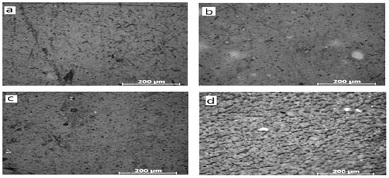
2.2.2. The Laboratory Test for Chemical Aging
2.3. Mechanical Aging
2.3.1. Mechanism of Mechanical Aging
2.3.2. The Laboratory Test for Mechanical Aging
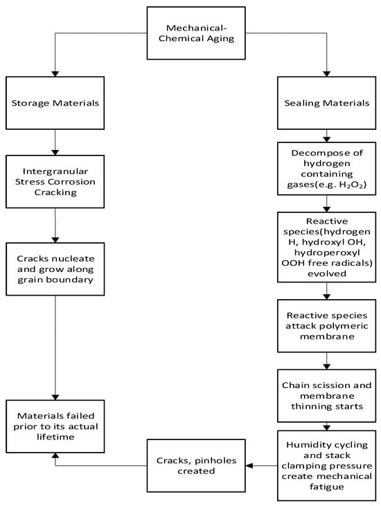
2.4. Mechanical–Chemical Aging
2.4.1. Mechanism of Mechanical–Chemical Aging
2.4.2. The Laboratory Test for Mechanical–Chemical Aging
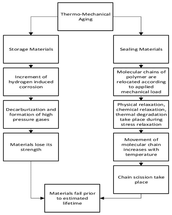
2.5. Thermo-Mechanical Aging
2.5.1. Mechanism of Thermo-Mechanical Aging
2.5.2. Laboratory Test for Thermo-Mechanical Aging
3. Durability Analysis of Hydrogen Sealing and Storage Materials through Aging Tests
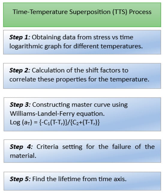
3.1. Durability Test Methods and Principles
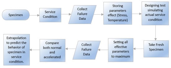
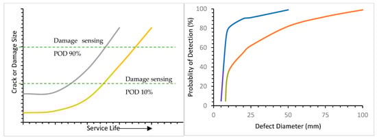
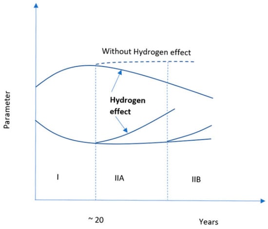
3.2. Service Life of Storage and Sealing Material under Simultaneous Multiple Aging
4. Key Factors Affecting Aging under the Hydrogen Environment
4.1. Effects of Temperature
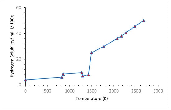
4.2. Effect of Pressure
4.3. Effects of Stress
4.4. Effects of Thermal Cycle
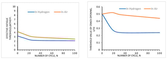
4.5. Effects of Environment
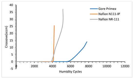
4.6. Effects of Alloying Elements
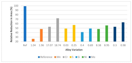
References
- Yue, M.; Lambert, H.; Pahon, E.; Roche, R.; Jemei, S.; Hissel, D. Hydrogen energy systems: A critical review of technologies, applications, trends and challenges. Renew. Sustain. Energy Rev. 2021, 146, 111180.
- Nicoletti, G.; Arcuri, N.; Nicoletti, G.; Bruno, R. A technical and environmental comparison between hydrogen and some fossil fuels. Energy Convers. Manag. 2015, 89, 205–213.
- Balasooriya, W.; Clute, C.; Schrittesser, B.; Pinter, G. A review on applicability, limitations, and improvements of polymeric materials in high-pressure hydrogen gas atmospheres. Taylor Fr. 2022, 62, 175–209.
- Fassbender, L. Hydrogen Safety Training for First Responders. 2010. Available online: https://www.hydrogen.energy.gov/docs/hydrogenprogramlibraries/pdfs/review10/scs015_fassbender_2010_o_web.pdf (accessed on 12 March 2023).
- Li, H.; Cao, X.; Liu, Y.; Shao, Y.; Nan, Z.; Teng, L.; Peng, W.; Bian, J. Safety of Hydrogen Storage and Transportation: An Overview on Mechanisms, Techniques, and Challenges. Energy Rep. 2022, 8, 6258–6269. Available online: https://www.sciencedirect.com/science/article/pii/S2352484722008332 (accessed on 13 March 2023).
- Barrera, O.; Bombac, D.; Chen, Y.; Daff, T.D.; Galindo-Nava, E.; Gong, P.; Haley, D.; Horton, R.; Katzarov, I.; Kermode, J.R.; et al. Understanding and mitigating hydrogen embrittlement of steels: A review of experimental, modelling and design progress from atomistic to continuum. J. Mater. Sci. 2018, 53, 6251–6290.
- Eghbali, P.; Gürbüz, M.U.; Ertürk, A.S.; Metin, Ö. In situ synthesis of dendrimer-encapsulated palladium(0) nanoparticles as catalysts for hydrogen production from the methanolysis of ammonia borane. Int. J. Hydrogen Energy 2020, 45, 26274–26285.
- Handbook on Ageing Management for Nuclear Power Plants—Google Scholar. Available online: https://scholar.google.com/scholar?hl=en&as_sdt=0%2C5&q=Handbook+on+Ageing+Management+for+Nuclear+Power+Plants&btnG= (accessed on 13 March 2023).
- Hansler, R.J.; Bellamy, L.J.; Akkermans, H.A. Ageing assets at major hazard chemical sites—The Dutch experience. Saf. Sci. 2022, 153, 105788.
- Research Report 509—Plant ageing: Management of…—Google Scholar. Available online: https://scholar.google.com/scholar?hl=en&as_sdt=0%2C5&q=Research+Report+509+-+Plant+ageing%3A+Management+of+equipment+containing+hazardous+fluids+or+pressure+%282006%29&btnG= (accessed on 18 March 2023).
- ARIA. Catastrophic Explosion of a Cyclohexane Cloud: Flixborough United Kingdom. 2008, pp. 1–9. Available online: http://www.aria.developpement-durable.gouv.fr/wp-content/files_mf/FD_5611_flixborough_1974_ang.pdf (accessed on 9 September 2023).
- Health and Safety Executive. Public Report of the Fire and Explosion at the ConocoPhillips Humber Refinery on 16 April 2001. Health and Safety Executive. Available online: https://www.yumpu.com/en/document/view/22334776/public-report-of-the-fire-and-explosion-at-the-conocophillips-hse (accessed on 9 September 2023).
- U.S. Chemical Safety Board. Chevron Richmond Refinery Pipe Rupture and Fire. Report No. 2012-03-I-CA-26. 2015. Available online: https://www.csb.gov/chevron-richmond-refinery-fire/ (accessed on 9 September 2023).
- Case Study: Power Plant Hydrogen Explosion—WHA International, Inc. Available online: https://wha-international.com/case-study-power-plant-hydrogen-explosion/ (accessed on 15 June 2023).
- CSB Investigation Finds 2010 Tesoro Refinery Fatal Explosion Resulted from High Temperature Hydrogen Attack Damage to Heat Exchanger—General News—News|CSB. Available online: https://www.csb.gov/csb-investigation-finds-2010-tesoro-refinery-fatal-explosion-resulted-from-high-temperature-hydrogen-attack-damage-to-heat-exchanger/ (accessed on 15 June 2023).
- Diebold, U. The surface science of titanium dioxide. Surf. Sci. Rep. 2003, 48, 53–229.
- Slobodyan, Z.V.; Nykyforchyn, H.M.; Petrushchak, O.I. Corrosion resistance of pipe steel in oil-water media. Mater. Sci. 2002, 38, 424–429.
- Ohaeri, E.; Eduok, U.; Szpunar, J. Hydrogen related degradation in pipeline steel: A review. Int. J. Hydrogen Energy 2018, 43, 14584–14617.
- Sun, Y.; Cheng, Y.F. Thermodynamics of spontaneous dissociation and dissociative adsorption of hydrogen molecules and hydrogen atom adsorption and absorption on steel under pipelining conditions. Int. J. Hydrogen Energy 2021, 46, 34469–34486.
- Hayden, L.E.; Stalheim, D. ASME B31.12 Hydrogen Piping and Pipeline Code Design Rules and Their Interaction with Pipeline Materials Concerns, Issues and Research. Am. Soc. Mech. Eng. Press. Vessel. Pip. Div. PVP 2010, 1, 355–361.
- Sharma, S.; Ghoshal, S.K. Hydrogen the Future Transportation Fuel: From Production to Applications. Renew. Sustain. Energy Rev. 2015, 43, 1151–1158. Available online: https://www.sciencedirect.com/science/article/pii/S1364032114010405 (accessed on 19 March 2023).
- Yamabe, J.; Nishimura, S.; Koga, A. A Study on Sealing Behavior of Rubber O-Ring in High Pressure Hydrogen Gas. SAE Int. J. Mater. Manuf. 2009, 2, 452–460. Available online: https://www.jstor.org/stable/26282777?casa_token=K9af06EzU1IAAAAA:_7GegdsxzpVSb9S4fTwAFfaJ8occyV_3Fqs_0P-mkiXlo7S0ll6MLC2mVO_LBxh5hw2uR5XHgAlcBJUCy_bugUCDxk0vPe8VzTUOt0si4eCoG_9qGxrk (accessed on 13 March 2023).
- Zubrin, R. The Hydrogen Hoax. New Atlantis 2007, 15, 9–20. Available online: https://www.jstor.org/stable/43152303?casa_token=cR8dWvg1DikAAAAA:cVZaZ1odOw7VAlnFmG89uCFiXnnH84umoewH-4Dgxy6Jy6BpbOqXeaqnkX7Uh2ktoY1a32aDCNDvIVIl408idd6AKJ-jXrRq5LOYUgJAkuJsIIqL3Vht (accessed on 12 March 2023).
- Nykyforchyn, H.; Tsyrulnyk, O.; Zvirko, O.; Hredil, M. Role of hydrogen in operational degradation of pipeline steel. Procedia Struct. Integr. 2020, 28, 896–902.
- Tiwari, G.P.; Bose, A.; Chakravartty, J.; Wadekar, S.; Totlani, M.; Arya; Fotedar, R. A study of internal hydrogen embrittlement of steels. Mater. Sci. Eng. A 2020, 286, 269–281.
- Dwivedi, S.; Vishwakarma, M. Hydrogen embrittlement in different materials: A review. Int. J. Hydrogen Energy 2018, 43, 21603–21616.
- Student, O.Z. Accelerated method for hydrogen degradation of structural steel. Mater. Sci. 1998, 34, 497–507.
- Shapovalov, V.I. Influence of Hydrogen on the Structure and Properties of Iron-Carbon Alloys; Metallurgiya: Moscow, Russia, 1982.
- Pokhmurskyi, V.I.; Fedorov, V.V. Influence of Hydrogen on the Diffusion Processes in Metals; Karpenko Physicomechanical Institute, Ukrainian Academy of Sciences: Kiev, Ukraine, 1998.
- Krutasova, E.I. Reliability of the Metal of Power-Generating Equipment; Énergoizdat: Moscow, Russia, 1981.
- Nykyforchyn, B.; Andrusiv, B.M.; Voldemarov, A.V.; Kutsyn, M.A. Evaluation of the effect of closure of fatigue cracks. Fiz.-Khim. Mekh. Mater. 1982, 18, 100–103.
- Hirakami, D.; Manabe, T.; Ushioda, K.; Noguchi, K.; Takai, K.; Hata, Y.; Hata, S.; Nakashima, H. Effect of Aging Treatment on Hydrogen Embrittlement of Drawn Pearlitic Steel Wire. ISIJ Int. 2016, 56, 893–898.
- Ogawa, Y.; Yamabe, J.; Matsunaga, H.; Matsuoka, S. Material performance of age-hardened beryllium–copper alloy, CDA-C17200, in a high-pressure, gaseous hydrogen environment. Int. J. Hydrogen Energy 2017, 42, 16887–16900.
- Yamabe, J.; Takagoshi, D.; Matsunaga, H.; Matsuoka, S.; Ishikawa, T.; Ichigi, T. High-strength copper-based alloy with excellent resistance to hydrogen embrittlement. Int. J. Hydrogen Energy 2016, 41, 15089–15094.
- Yamabe, J.; Fujiwara, H.; Nishimura, S. Fracture analysis of rubber sealing meterial for high pressure hydrogen vessel. Nihon Kikai Gakkai Ronbunshu A Hen/Trans. Jpn. Soc. Mech. Eng. Part A 2009, 75, 1063–1073.
- Yokoyama, K.; Ogawa, T.; Takashima, K.; Asaoka, K.; Sakai, J. Hydrogen embrittlement of Ni-Ti superelastic alloy aged at room temperature after hydrogen charging. Mater. Sci. Eng. A 2007, 466, 106–113.
- Ogawa, T.; Oda, T.; Maruoka, K.; Sakai, J. Effect of aging at room temperature on hydrogen embrittlement behavior of Ni-Ti superelastic alloy immersed in acidic fluoride solution. Int. J. Mech. Mater. Eng. 2015, 10, 11.
- Tal-Gutelmacher, E.; Eliezer, D. Hydrogen cracking in titanium-based alloys. J. Alloy. Compd. 2005, 404–406, 621–625.
- Omura, T.; Nakamura, J.; Hirata, H.; Jotoku, K.; Ueyama, M.; Osuki, T.; Terunuma, M. Effect of Surface Hydrogen Concentration on Hydrogen Embrittlement Properties of Stainless Steels and Ni Based Alloys. ISIJ Int. 2016, 56, 405–412.
- Li, G.; Zhu, D.; Jia, W.; Zhang, F. Analysis of the aging mechanism and life evaluation of elastomers in simulated proton exchange membrane fuel cell environments. e-Polymers 2021, 21, 921–929.
- Zhang, E.; Liu, J.; Zhang, C.; Zheng, P.; Nakanishi, Y.; Wu, T. State-of-Art Review on Chemical Indicators for Monitoring the Aging Status of Oil-Immersed Transformer Paper Insulation. Energies 2023, 16, 1396.
- Wetegrove, M.; Duarte, M.J.; Taube, K.; Rohloff, M.; Gopalan, H.; Scheu, C.; Dehm, G.; Kruth, A. Preventing Hydrogen Embrittlement: The Role of Barrier Coatings for the Hydrogen Economy. Hydrogen 2023, 4, 307–322.
- Zhang, M.; Lv, H.; Kang, H.; Zhou, W.; Zhang, C. A Literature Review of Failure Prediction and Analysis Methods for Composite High-Pressure Hydrogen Storage Tanks. Int. J. Hydrogen Energy 2019, 44, 25777–25799. Available online: https://www.sciencedirect.com/science/article/pii/S0360319919329106 (accessed on 25 December 2022).
- Klopffer, M.; Berne, P.; Castagnet, S.; Weber, M. Pipes for Distributing Mixtures of Hydrogen and Natural Gas. Evolution of Their Transport and Mechanical Properties after an Ageing under an Hydrogen Environment. 2010. Available online: https://www.osti.gov/etdeweb/biblio/21400887 (accessed on 2 November 2022).
- Zheng, C.X.; Wang, L.; Li, R.; Wei, Z.X.; Zhou, W.W. Fatigue test of carbon epoxy composite high pressure hydrogen storage vessel under hydrogen environment. J. Zhejiang Univ. Sci. A 2013, 14, 393–400.
- Feng, X.; Shi, Y.; Zhang, W.; Volodymyr, K. Hydrogen Embrittlement Failure Behavior of Fatigue-Damaged Welded TC4 Alloy Joints. Crystals 2023, 13, 512.
- Brownell, M.; Frischknecht, A.L.; Wilson, M.A. Subdiffusive High-Pressure Hydrogen Gas Dynamics in Elastomers. Macromolecules 2022, 55, 3788–3800.
- Wilson, M.A.; Frischknecht, A.L. High-pressure hydrogen decompression in sulfur crosslinked elastomers. Int. J. Hydrogen Energy 2022, 47, 15094–15106.
- Zhou, C.; Chen, G.; Liu, P.; Guohua, C.Z.; Liu, C.P. Finite element analysis of sealing performance of rubber D-ring seal in high-pressure hydrogen storage vessel. J. Fail. Anal. Prev. 2018, 18, 846–855.
- Zatoń, M.; Rozière, J.; Jones, D.J. Current understanding of chemical degradation mechanisms of perfluorosulfonic acid membranes and their mitigation strategies: A review. Sustain. Energy Fuels 2017, 1, 409–438.
- LaConti, A.; Hamdan, M.; McDonald, R.C. Mechanisms of membrane degradation. In Handbook of Fuel Cells; Wiley: Hoboken, NJ, USA, 2003.
- Danilczuk, M.; Corns, F.D.; Schlick, S. Visualizing chemical reactions and crossover processes in a fuel cell inserted in the esr resonator: Detection by spin trapping of oxygen radicals, nafion-derived fragments, and hydrogen and deuterium atoms. J. Phys. Chem. B 2009, 113, 8031–8042.
- Lee, S.Y.; Cho, E.; Lee, J.H.; Kim, H.J.; Lim, T.H.; Oh, I.H.; Won, J. Effects of Purging on the Degradation of PEMFCs Operating with Repetitive On/Off Cycles. J. Electrochem. Soc. 2007, 154, B194.
- Healy, J. Aspects of the chemical degradation of PFSA ionomers used in PEM fuel cellsx. Fuel Cells 2005, 5, 302–308.
- Kusoglu, A.; Weber, A.Z. A Mechanistic Model for Pinhole Growth in Fuel-Cell Membranes during Cyclic Loads. J. Electrochem. Soc. 2014, 161, E3311–E3322.
- Gittleman, C.S.; Coms, F.D.; Lai, Y.-H. Chapter 2—Membrane Durability: Physical and Chemical Degradation A2. Mod. Top. Polym. Electrolyte Fuel Cell Degrad. 2012, 15–88. Available online: http://www.sciencedirect.com/science/article/pii/B9780123869364100028 (accessed on 19 July 2022).
- De Moor, G. Understanding membrane failure in PEMFC: Comparison of diagnostic tools at different observation scales. Fuel Cells 2012, 12, 356–364.
- Harris, Z.; Burns, J.T. A The Effect of Isothermal Heat Treatment on Hydrogen Environment-Assisted Cracking Susceptibility in Monel K-500. Mater. Sci. Eng. A 2019, 764, 138249. Available online: https://www.sciencedirect.com/science/article/pii/S0921509319310354 (accessed on 11 November 2022).
- Nykyforchyn, H.; Lunarska, E.; Tsyrulnyk, O.T.; Nikiforov, K.; Genarro, M.E.; Gabetta, G. Environmentally assisted ‘in-bulk’ steel degradation of long term service gas trunkline. Eng. Fail. Anal. 2010, 17, 624–632.
- Robert, M. The Impact of Chemical-Mechanical Ex Situ Aging on PFSA Membranes for Fuel Cells. Membranes 2021, 11, 366.
- Balitskii, A.; Ivaskevych, L. Temperature Dependences of Age-Hardening Austenitic Steels Mechanical Properties in Gaseous Hydrogen. 2009. Available online: https://www.researchgate.net/profile/Alexander-Balitskii/publication/281269596_Temperature_Dependences_of_Age-hardening_Austenitic_Steels_Mechanical_Properties_in_Gaseous_Hydrogen/links/55dd955908aeb41644aefe8e/Temperature-Dependences-of-Age-hardening-Austenitic-Steels-Mechanical-Properties-in-Gaseous-Hydrogen.pdf (accessed on 12 November 2022).
- Cui, T.; Lin, C.W.; Chien, C.H.; Chao, Y.J.; Van Zee, J.W. Service life estimation of liquid silicone rubber seals in polymer electrolyte membrane fuel cell environment. J. Power Sources 2011, 196, 1216–1221.
- Brown, R.P. Survey of status of test methods for accelerated durability testing. Polym. Test. 1991, 10, 3–30.
- Burgess, R.; Post, M.; Buttner, W.; Rivkin, C. High Pressure Hydrogen Pressure Relief Devices: Accelerated Life Testing and Application Best Practices. 2017. Available online: https://www.osti.gov/biblio/1408284 (accessed on 24 December 2022).
- Liu, D.; Case, S. Durability Study of Proton Exchange Membrane Fuel Cells under Dynamic Testing Conditions with Cyclic Current Profile. J. Power Sources 2006, 162, 521–531. Available online: https://www.sciencedirect.com/science/article/pii/S0378775306012493 (accessed on 24 December 2022).
- Fukushima, K.; Cai, H.; Nakada, M.; Miyano, Y. Determination of Time-Temperature Shift Factor for Long-Term Life Prediction of Polymer Composites. 2009. Available online: https://iccm-central.org/Proceedings/ICCM17proceedings/Themes/Behaviour/AGINGMOIST&VISCOEPROP/INT-AGINGMOIST&VISCOEPROP/IF1.1Fukushima.pdf (accessed on 3 April 2023).
- Irving, P.E. Development of service life prognosis systems for hydrogen energy devices. Gaseous Hydrog. Embrittlement Mater. Energy Technol. Mech. Model. Futur. Dev. 2012, 1, 430–468.
- Hiemenz, P.C.; Lodge, T.P. Polymer Chemistry, 2nd ed.; Taylor & Francis: Boca Raton, FL, USA, 2007; pp. 338–339.
- Kundu, S.; Simon, L.; Fowler, M.W. Comparison of two accelerated NafionTM degradation experiments. Polym. Degrad. Stab. 2008, 93, 214–224.
- Andrews, R.D.; Tobolsky, A.V. Elastoviscous properties of polyisobutylene. IV. Relaxation time spectrum and calculation of bulk viscosity. J. Polym. Sci. 1951, 7, 221–242.
- Struik, L.C.E. Physical aging in plastics and other glassy materials. Polym. Eng. Sci. 1977, 17, 165–173.
- Williams, M.L.; Landel, R.F.; Ferry, J.D. The Temperature Dependence of Relaxation Mechanisms in Amorphous Polymers and Other Glass-forming Liquids. J. Am. Chem. Soc. 1955, 77, 3701–3707.
- Li, G.; Tan, J.; Gong, J. Chemical aging of the silicone rubber in a simulated and three accelerated proton exchange membrane fuel cell environments. J. Power Sources 2012, 217, 175–183.
- Tan, J.; Chao, Y.J.; Yang, M.; Lee, W.K.; Van Zee, J.W. Chemical and mechanical stability of a Silicone gasket material exposed to PEM fuel cell environment. Int. J. Hydrogen Energy 2011, 36, 1846–1852.
- Cui, T.; Lin, C.W.; Chien, C.H.; Chao, Y.J.; Van Zee, J. Service life prediction of seal in PEM fuel cells. Conf. Proc. Soc. Exp. Mech. Ser. 2011, 5, 25–32.
- Gittleman, C.; Lai, Y.; Miller, D. Durability of Perfluorosulfonic Acid Membranes for PEM Fuel Cells. 2005. Available online: https://www.researchgate.net/profile/Craig-Gittleman-2/publication/265075095_Durability_of_Perfluorosulfonic_Acid_Membranes_for_PEM_Fuel_Cells/links/547321ef0cf2d67fc035dff1/Durability-of-Perfluorosulfonic-Acid-Membranes-for-PEM-Fuel-Cells.pdf (accessed on 11 August 2022).
- Nák, V.Z.; Saldan, I.; Giannakoudakis, D.; Barczak, M.; Pasán, J. Factors affecting hydrogen adsorption in metal–organic frameworks: A short review. Nanomaterials 2021, 11, 1638.
- Eliezer, D.; Böllinghaus, T.H. Hydrogen effects in titanium alloys. Gaseous Hydrog. Embrittlement Mater. Energy Technol. 2012, 2, 668–706.
- Tomi, T. Effects of Hydrogen upon the Properties of Thermo Mechanical Controlled Process (TMCP) Steel; Croatian Metallurgical Society: Zagreb, Croatia, 2015.
- Fukuyama, S.; Sun, D.; Zhang, L.; Wen, M.; Yokogawa, K. Effect of temperature on hydrogen environment embrittlement of type 316 series austenitic stainless steels at low temperatures. J. Jpn. Inst. Met. 2003, 67, 456–459.
- Duthil, P. Material properties at low temperature. In Proceedings of the CAS-CERN Accelerator School: Superconductivity for Accelerators, Erice, Italy, 24 April–4 May 2013; pp. 77–95.
- Wu, Y.; Wang, D.; Zhang, W.; Zhang, J. Experimental research of thermal-oxidative aging on the mechanics of aero-nbr. J. Test. Eval. 2013, 42, 568–572.
- Dubovský, M.; Božek, M.; Olšovský, M. Degradation of aviation sealing materials in rapeseed biodiesel. J. Appl. Polym. Sci. 2015, 132.
- Hohe, J.; Neubrand, A.; Fliegener, S.; Appel, S. Performance of Fiber Reinforced Materials under Cryogenic Conditions—A Review. Compos. Part A Appl. Sci. Manuf. 2021, 141, 106226. Available online: https://www.sciencedirect.com/science/article/pii/S1359835X20304620 (accessed on 13 September 2023).
- Raj, A.; Alvi, S.M.A.A.; Islam, K.; Motalab, M.; Xu, S. An Atomistic Study of the Tensile Deformation of Carbon Nanotube–Polymethylmethacrylate Composites. Polymers 2023, 15, 2956.
- Xiong, X.; Tao, X.; Zhou, Q.J.; Li, J.X.; Volinsky, A.A.; Su, Y.J. Hydrostatic Pressure Effects on Hydrogen Permeation in A514 Steel during Galvanostatic Hydrogen Charging. Corros. Sci. 2016, 112, 86–93. Available online: https://www.sciencedirect.com/science/article/pii/S0010938X16302943 (accessed on 31 March 2023).
- Fujiwara, H.; Nishimura, S. Evaluation of Hydrogen Dissolved in Rubber Materials under High-Pressure Exposure Using Nuclear Magnetic Resonance. Polym. J. 2012, 44, 832–837. Available online: https://www.nature.com/articles/pj2012111 (accessed on 27 December 2022).
- Martin, M.; Weber, S.; Theisen, W.; Michler, T.; Naumann, J. Effect of Alloying Elements on Hydrogen Environment Embrittlement of AISI Type 304 Austenitic Stainless Steel. Int. J. Hydrogen Energy 2011, 36, 15888–15898. Available online: https://www.sciencedirect.com/science/article/pii/S036031991102091X (accessed on 23 December 2022).
- Sun, B.; Lu, W.; Gault, B.; Ding, R.; Makineni, S.K.; Wan, D.; Wu, C.-H.; Chen, H.; Ponge, D.; Raabe, D. Chemical heterogeneity enhances hydrogen resistance in high-strength steels. Nat. Mater. 2021, 20, 1629–1634.
- Anyalebechi, P.N. Analysis of the Effects of Alloying Elements on Hydrogen Solubility in Liquid Aluminum Alloys. Scr. Metall. Et Mater. 1995, 33, 1209–1216. Available online: https://www.sciencedirect.com/science/article/pii/0956716X95003734 (accessed on 23 December 2022).


