 +1 credit
| Version | Summary | Created by | Modification | Content Size | Created at | Operation |
|---|---|---|---|---|---|---|
| 1 | Hossein malekinejadbahabadi | -- | 2823 | 2023-10-15 15:32:35 | | | |
| 2 | Catherine Yang | -40 word(s) | 2783 | 2023-10-16 03:47:27 | | | | |
| 3 | Catherine Yang | Meta information modification | 2783 | 2023-10-16 03:51:28 | | |
Video Upload Options
Adhesive bonding is widely seen as the most optimal method for joining composite materials, bringing significant benefits over mechanical joining, such as lower weight and reduced stress concentrations. Adhesively bonded composite joints find extensive applications where cyclic fatigue loading takes place, but this might ultimately lead to crack damage and safety issues. Consequently, it has become essential to study how these structures behave under fatigue loads and identify the remaining gaps in knowledge to give insight into new possibilities. The fatigue life of adhesively bonded composite joints is influenced by various parameters, including joint configuration and material properties of adherends and adhesive. Numerous studies with varying outcomes have been documented in the literature. However, due to the multitude of influential factors, deriving conclusive insights from these studies for practical design purposes has proven to be challenging. Hence, this research aims to address this challenge by discussing different methods to enhance the fatigue performance of adhesively bonded composite joints. Additionally, it provides a comprehensive overview of the existing literature on adhesively bonded composite joints under cyclic fatigue loading, focusing on three main aspects: adherends modification, adhesive modification, and joints configurations. Since the effect of modifying the adhesive, adherends, and joint configurations on fatigue performance has not been comprehensively studied in the literature.
1. Introduction
The majority of applications that utilize adhesively bonded joints are exposed to high cyclic fatigue loading over their lifespan, and fatigue failure is well known to be one of the primary causes of catastrophic failure in many cases (up to 50-90%) [1]. This fact highlights the importance of studying fatigue behavior in adhesively bonded joints. This is particularly crucial, especially when designing under safe life and damage tolerance philosophies [2][3]. The fatigue life of a composite adhesive joint is impacted by the distribution of stresses along the adhesive and adherends, as well as their interface, which are a function of various parameters, including joint configurations, material properties of adherends and adhesive [4], service temperature [5][6], humidity level [7], manufacturing process, and associated surface treatment [8]. The fatigue life can be controlled by modifying these parameters, such as hybridizing the adherends and adhesive [9][10], incorporating additive particles [11], and adjusting the configurations [12]. This research aims to provide a comprehensive overview of the existing literature on adhesive bonded composite joints under fatigue loading, focusing on three main aspects: 1. adherend modification, 2. adhesive modification, and 3. joint configurations.
2. Joint configuration and geometry
This section aims to investigate the impact of joint configuration and geometry parameters, such as overlap length (l), overlap geometry (interface configuration), corner geometry, adhesive thickness (ta), adherends thickness (T) on the fatigue behavior of composite adhesive joints (see Figure 1).
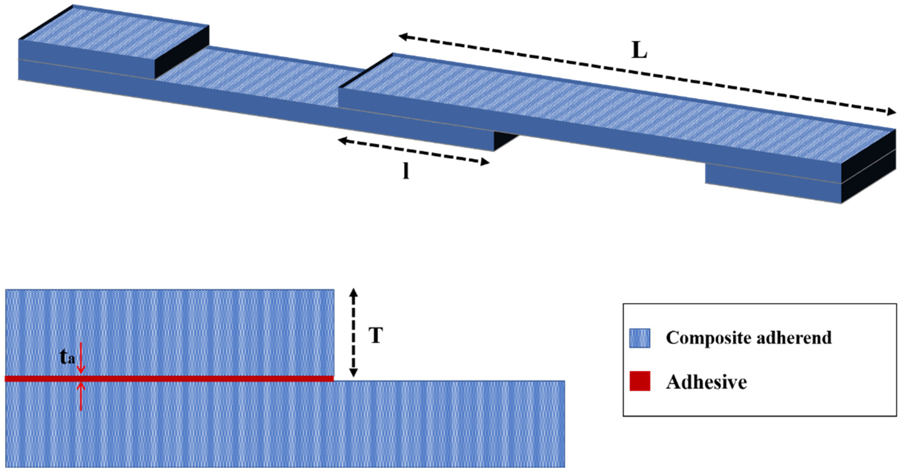
Figure 1. Design parameters of conventional SLJ.
The study findings indicated that the fatigue strength of double-lap joints was significantly superior to that of SLJs. Overall, the findings indicate that decreasing the scarf angle results in an improvement in the fatigue strength of scarf joints, driven by an increase in the bonded area. This is consistent with the conclusions drawn in other studies [13][14][15]. Scarf joints exhibited a higher fatigue life than butt joints of equal CFRP adherends thickness, regardless of the scarf angle. As the thickness of the CFRP adherends in the butt joint increased, the fatigue strength is reduced due to the volume effect of CFRP, and the dominant failure mode shift from primarily delamination to cohesive failure. Figure 2 illustrates the increase in fatigue strength, specifically the load threshold at which the specimen has withstood over 10 million cycles, known as the endurance limit, in comparison to the SLJ.To ensure comparability, the fatigue load is normalized by dividing it by the overlap area for each configuration. This adjustment takes into account the size of the adherends and the adhesive layer used.
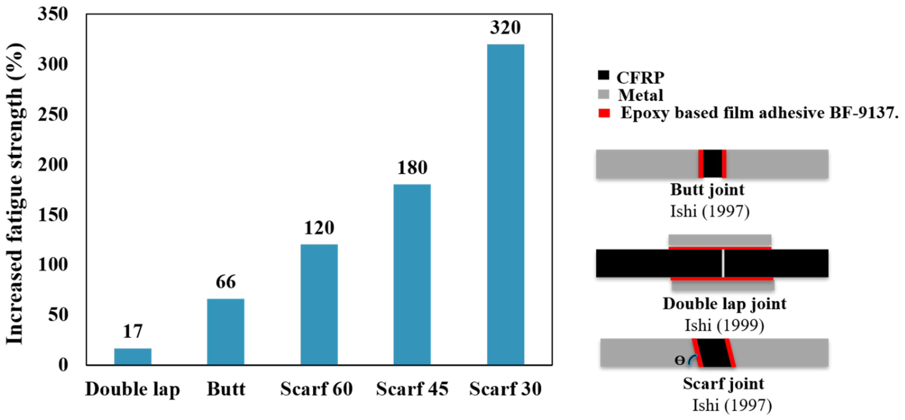
Figure 2. Fatigue strength (corresponding to 1e6 cycle) improvement for different configurations in comparison to the SLJ. (Adapted from [12][16]).
The test results showed that the wavy lap joint had a considerably longer fatigue life and higher strength than the conventional lap joint (see Figure 3). The analysis of the failure surface in a wavy joint under fatigue loading revealed that cohesive failure was the primary mode of failure. However, in the case of a conventional SLJ, unstable shear breakage was observed specifically in the middle section of the overlap length.
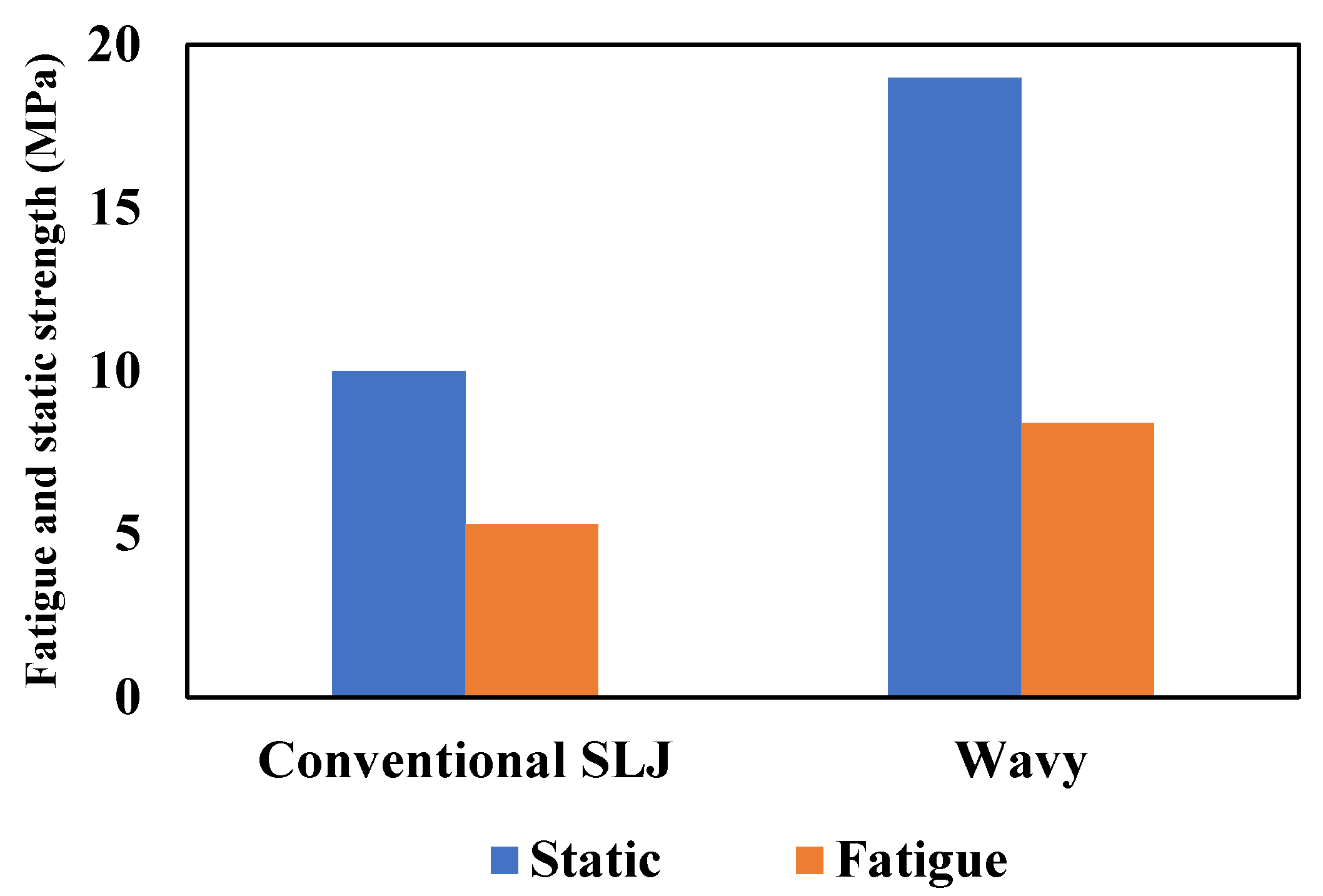
Figure 3. Effect of wavy interface on the fatigue and static strength of joints (Adapted from [17]).
The resulting improvement in fatigue strength for different configurations is depicted in Figure 4. To allow for direct comparisons in the fatigue performance, the fatigue strength is normalized by dividing it by the overlap area. This normalization takes into account the use of a similar adhesive for the various configurations presented. In conclusion, the wavy joint configuration can lead to improved joint strength compared to conventional SLJs, particularly under fatigue loading conditions. The reduction of peel stresses and stress concentrations at the joint ends are key factors contributing to these improvements.
The final aspect to consider is that utilizing non-flat overlap regions can enhance the fatigue strength and behavior of adhesively bonded joints and the significance of locally modifying adherend geometry becomes even more crucial when joint configurations are limited by their application. However, it is essential to address the complexity of manufacturing and the lack of precise control over the geometry of composite adherends, as these factors can lead to variations and increased cost.
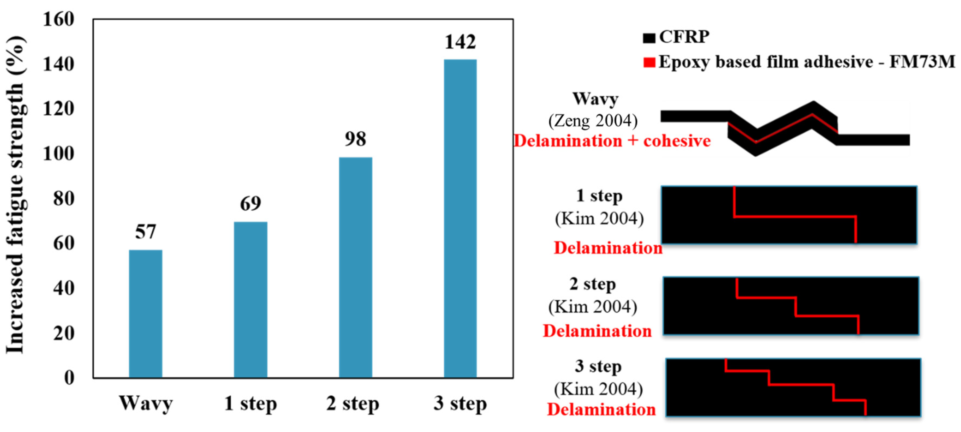
Figure 4. Fatigue strength improvement for different configurations compared to conventional SLJs (Adapted from [17][18]).
2.1. Corner Geometry and Overlap Length
Although the length of the overlap in adhesively bonded joints has a significant impact on both the initiation and propagation of fatigue crack growth, more so than factors like corner fillet [19], as shown in Figure 5, the strength of adhesively bonded composite joints (the highest tensile stress that can be applied to the bonded joint without causing failure until 1e 6 cycles) has been enhanced by incorporating a spew fillet at the overlap ends. This can be explained by the reduction of stress concentration within both the adhesive and the adherends [20][21].
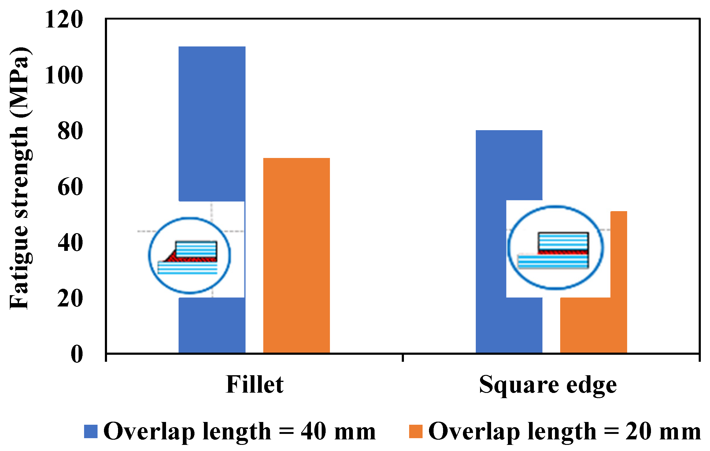
Figure 5. Effect of overlap length vs. corner fillet on fatigue strength [19].
2.2 Adhesive Thickness
It is recognized by the classic theory that when the thickness of the adhesive increases, the peel stress also increases, leading to a decrease in the fatigue life [22]. While adhesive thickness is increased, the length of the "moment arm" over which the applied force acts is effectively extended and makes higher moment arm, subsequently leading to increased peel stresses at the edges of the adhesive bond. To support this considering that peel stress is influenced by multiple factors, it becomes necessary to conduct a numerical investigation into the impact of adhesive thickness on peel stress. In [23][24], the finite element analysis revealed that the peel stress increased with greater adhesive thickness.
The thickness of the adhesive also affects the failure mode so that failure occurred withing the adhesive layer, and with an increase in thickness, the failure mode changes and delamination is raised due to an increase in peel stresses [24]. As previously discussed, it has been observed that peel stress rises in response to an increase in adhesive thickness. Given that peel stress significantly impacts the composite adherends at the ends of the overlap (where peel stress is most pronounced), this leads to a heightened risk of deamination, as depicted in Figure 6.
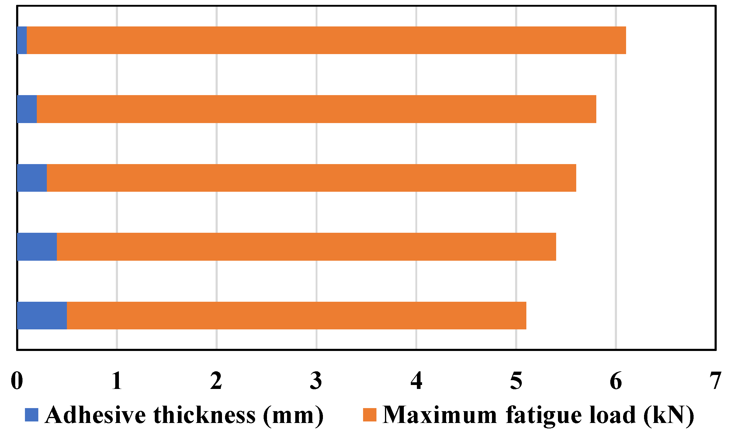
Figure 6. How the adhesive thickness affects the highest load that can be applied to the bonded joint without causing failure in 1e6 cycles (Adapted from [25]).
3. Adherend modification
3.1. Stacking Sequence and Interface Ply Orientation of Adherends
As shown in Figure 7, as long as the interface plies are placed at 0º, debonding occurs within the adhesive region in a cohesive manner and final failure occurred in the 0º adjacent layer. However, in the case of 45° interface plies, debonding happens through a combination of cyclic debonding in the adhesive and delamination in the ±45° plies of the laminate adherend. In more detail, the crack continues to grow until it reaches the layer with 0º orientation and then final failure occurs. For specimens with 90° plies, damage initiates with transverse cracking in the 90° layers of the strap adherend, and then progresses through delamination failure until it reaches the first 0° ply in the strap adherend (see Figure 7).
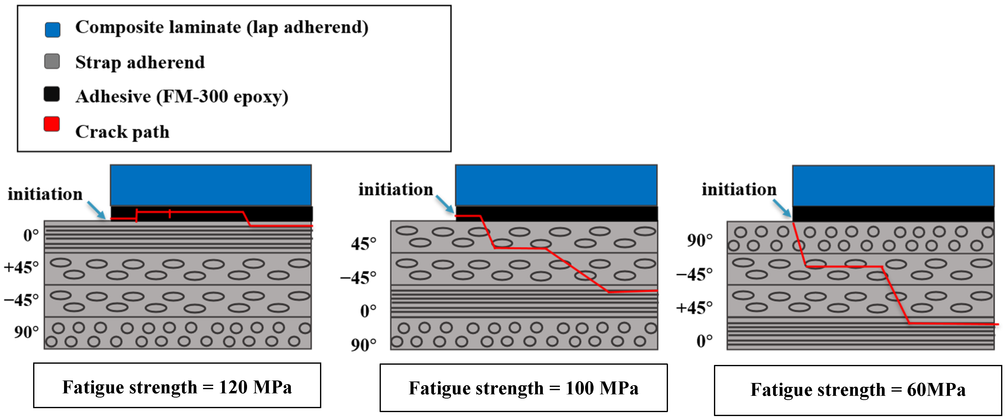
Figure 7. Changing crack path due to adhesive adjacent composite adherends layer orientation (0/+45/-45/90), (45/-45/0/90), (90/-45/+45/0) (Adapted from [26][27][28]).
In general, based on existing literature, it’s obvious that the stacking sequence and the orientation of adhesive adjacent layer have an impact on fatigue cracks path. Consequently, this affects both fatigue strength and fatigue life. Nonetheless, the impact of these factors on fatigue strength varies significantly based on the joint configuration. As previously discussed, using unidirectional fibers aligned with the load direction results in greater fatigue strength. The least favorable stacking sequence involves a perpendicular orientation, particularly evident in SLJs. However, in lap strap joints, these effects tend to diminish.
3.2. Surface Treatment
A surface with an optimized amount of roughness can result in the highest fatigue life due to several reasons, including an increase in the bonded area, enhancement of mechanical locking, and retardation of crack growth. Conversely, a surface that is too rough can lead to the formation of voids and stress concentration at the adhesive/adherend interface [29]. Surface treatments applied to adherends can impact the behavior of composite bonded joints during fatigue and static loading. However, this influence could depend on factors like the joint configuration and surface treatment parameters (such as surface roughness). As a result, these treatments might either enhance or degrade the strength of the joints.
4. Adhesive modification
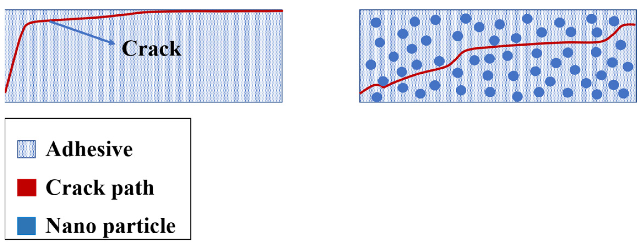
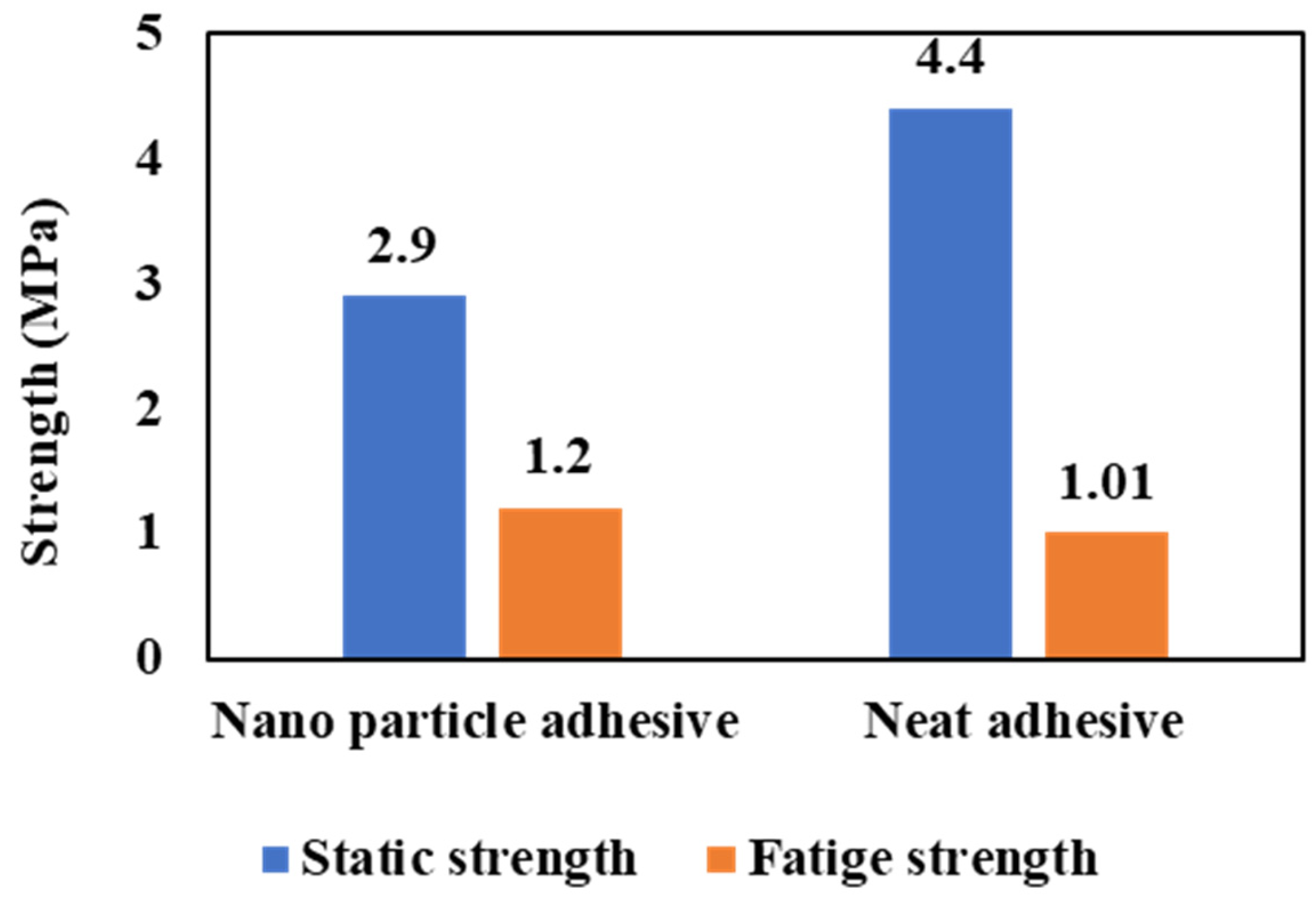
4.1. Nano-Reinforced Adhesive Layers
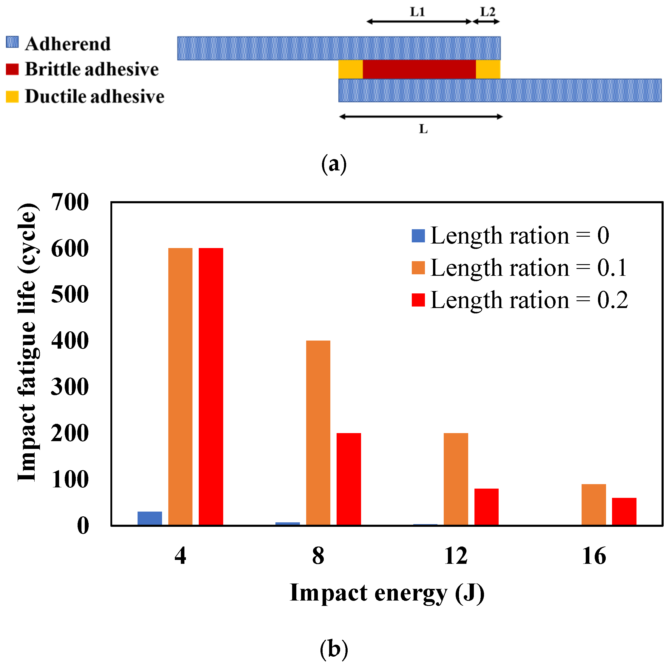
4.2. Mixed Adhesive Layers
References
- Ishii, K.; Imanaka, M.; Nakayama, H.; Kodama, H. Fatigue failure criterion of adhesively bonded CFRP/metal joints under multiaxial stress conditions. Compos. Part A Appl. Sci. Manuf. 1998, 29, 415–422.
- da Silva, L.F.M.; Öchsner, A.A.R. Handbook of Adhesion Technology: Second Edition; Springer: Cham, Switzerland, 2018; Volume 2, ISBN 9783319554112.
- Khashaba, U.A.; Najjar, I.M.R.; Almitani, K.H. Failure analysis of scarf adhesive joints modified with SiC-nanoparticles under fatigue loading at room temperature. Compos. Sci. Technol. 2022, 221, 109301.
- De Goeij, W.C.; Van Tooren, M.J.L.; Beukers, A. Composite adhesive joints under cyclic loading. Mater. Des. 1999, 20, 213–221.
- de Castro Lopes, F.V.B.; Akhavan-Safar, A.; Carbas, R.J.C.; Marque, E.A.S.; Goyal, R.; Jennings, J.; da Silva, L.F.M. The role of loading mode on the property degradation of adhesives at high temperatures. Fatigue Fract. Eng. Mater. Struct. 2023, 46, 1848–1863.
- Zamani, P.; Jaamialahmadi, A.; da Silva, L.F.M. Fatigue life evaluation of Al-GFRP bonded lap joints under four-point bending using strain-life criteria. Int. J. Adhes. Adhes. 2023, 122, 103338.
- Beber, V.C.; Schneider, B.; Brede, M. Influence of Temperature on the Fatigue Behaviour of a Toughened Epoxy Adhesive. J. Adhes. 2016, 92, 778–794.
- de Castro Lopes, F.V.B.; Akhavan-Safar, A.; Carbas, R.J.C.; Marques, E.A.S.; Goyal, R.; Jennings, J.; da Silva, L.F.M. The interaction of loading mode and humidity on the properties degradation of an epoxy adhesive subjected to strength, fracture, and fatigue tests. J. Appl. Polym. Sci. 2023, 140, e53490.
- de Barros, S.; Kenedi, P.P.; Ferreira, S.M.; Budhe, S.; Bernardino, A.J.; Souza, L.F.G. Influence of mechanical surface treatment on fatigue life of bonded joints. J. Adhes. 2017, 93, 599–612.
- Javaid, U.; Ling, C.; Cardiff, P. Mechanical performance of carbon-glass hybrid composite joints in quasi-static tension and tension-tension fatigue. Eng. Fail. Anal. 2020, 116, 104730.
- Ramírez, F.M.G.; Garpelli, F.P.; de Sales, R.C.M.; Cândido, G.M.; Arbelo, M.A.; Shiino, M.Y.; Donadon, M.V. Hygrothermal effects on the fatigue delamination growth onset in interlayer toughened CFRP joints. Int. J. Fatigue 2020, 138, 105729.
- Zamani, P.; Alaei, M.H.; da Silva, L.F.M.; Ghahremani-Moghadam, D. On the static and fatigue life of nano-reinforced Al-GFRP bonded joints under different dispersion treatments. Fatigue Fract. Eng. Mater. Struct. 2022, 45, 1088–1110.
- Moreira, R.D.F.; de Moura, M.F.S.F.; Silva, F.G.A.; Reis, J.P. High-cycle fatigue analysis of adhesively bonded composite scarf repairs. Compos. Part B Eng. 2020, 190, 107900.
- Olajide, S.O.; Kandare, E.; Khatibi, A.A. Fatigue life uncertainty of adhesively bonded composite scarf joints–an airworthiness perspective. J. Adhes. 2017, 93, 515–530.
- Yoo, J.S.; Truong, V.H.; Park, M.Y.; Choi, J.H.; Kweon, J.H. Parametric study on static and fatigue strength recovery of scarf-patch-repaired composite laminates. Compos. Struct. 2016, 140, 417–432.
- Ishii, K.; Imanaka, M.; Nakayama, H.; Kodama, H. Evaluation of the fatigue strength of adhesively bonded CFRP/metal single and single-step double-lap joints. Compos. Sci. Technol. 1999, 59, 1675–1683.
- Zeng, Q.; Sun, C.T. Fatigue performance of a bonded wavy composite lap joint. Fatigue Fract. Eng. Mater. Struct. 2004, 27, 413–422.
- Kim, J.H.; Park, B.J.; Han, Y.W. Evaluation of fatigue characteristics for adhesively-bonded composite stepped lap joint. Compos. Struct. 2004, 66, 69–75.
- Meneghetti, G.; Quaresimin, M.; Ricotta, M. Damage mechanisms in composite bonded joints under fatigue loading. Compos. Part B Eng. 2012, 43, 210–220.
- Lang, T.P.; Mallick, P.K. Effect of spew geometry on stresses in single lap adhesive joints. Int. J. Adhes. Adhes. 1998, 18, 167–177.
- da Silva, L.F.M.; Adams, R.D. Joint strength predictions for adhesive joints to be used over a wide temperature range. Int. J. Adhes. Adhes. 2007, 27, 362–379.
- Hart-Smith, L.J. Designing to Minimize Peel Stresses in Adhesive-Bonded Joints; Douglas Aircraft Co., McDonnell Douglas Corp.: Long Beach, CA, USA, 1985.
- Tang, J.H.; Sridhar, I.; Srikanth, N. Static and fatigue failure analysis of adhesively bonded thick composite single lap joints. Compos. Sci. Technol. 2013, 86, 18–25.
- Sekiguchi, Y.; Sato, C. Effect of bond-line thickness on fatigue crack growth of structural acrylic adhesive joints. Materials 2021, 14, 1723.
- Osiyemi, S.O. The Fatigue Performance of Adhesively Bonded Fibre-Composite Joints. Ph.D. Thesis, University of London, London, UK, 1992.
- Johnson, W.S.; Mall, S. Influence of interface ply orientation on fatigue damage of adhesively bonded composite joints. J. Compos. Technol. Res. 1986, 8, 82–93.
- Mall, S.; Johnson, W.S.; Everett, R.A. Cyclic Debonding of Adhesively Bonded Composites BT—Adhesive Joints: Formation, Characteristics, and Testing; Mittal, K.L., Ed.; Springer: Boston, MA, USA, 1984; pp. 639–658. ISBN 978-1-4613-2749-3.
- Casas-Rodriguez, J.P.; Ashcroft, I.A.; Silberschmidt, V.V. Damage in adhesively bonded CFRP joints: Sinusoidal and impact-fatigue. Compos. Sci. Technol. 2008, 68, 2663–2670.
- Davis, M.; Bond, D. Principles and practices of adhesive bonded structural joints and repairs. Int. J. Adhes. Adhes. 1999, 19, 91–105.
- Kang, M.-H.; Choi, J.-H.; Kweon, J.-H. Fatigue life evaluation and crack detection of the adhesive joint with carbon nanotubes. Compos. Struct. 2014, 108, 417–422.
- Gültekin, K.; Akpinar, S.; Gürses, A.; Eroglu, Z.; Cam, S.; Akbulut, H.; Keskin, Z.; Ozel, A. The effects of graphene nanostructure reinforcement on the adhesive method and the graphene reinforcement ratio on the failure load in adhesively bonded joints. Compos. Part B Eng. 2016, 98, 362–369.
- Khashaba, U.A.; Aljinaidi, A.A.; Hamed, M.A. Fatigue and reliability analysis of nano-modified scarf adhesive joints in carbon fiber composites. Compos. Part B 2017, 1201, 3–117.

