Your browser does not fully support modern features. Please upgrade for a smoother experience.
Submitted Successfully!
 +1 credit
Thank you for your contribution! You can also upload a video entry or images related to this topic.
For video creation, please contact our Academic Video Service.
Video Upload Options
We provide professional Academic Video Service to translate complex research into visually appealing presentations. Would you like to try it?
Cite
If you have any further questions, please contact Encyclopedia Editorial Office.
Wu, T.; You, D.; Gao, H.; Lian, P.; Ma, W.; Zhou, X.; Wang, C.; Luo, J.; Zhang, H.; Tan, H. Structure of Piezoelectric Accelerometers. Encyclopedia. Available online: https://encyclopedia.pub/entry/49752 (accessed on 16 July 2026).
Wu T, You D, Gao H, Lian P, Ma W, Zhou X, et al. Structure of Piezoelectric Accelerometers. Encyclopedia. Available at: https://encyclopedia.pub/entry/49752. Accessed July 16, 2026.
Wu, Tianqiong, Di You, Huayun Gao, Pinghua Lian, Weigang Ma, Xinyi Zhou, Chuanmin Wang, Jianghai Luo, Haibo Zhang, Hua Tan. "Structure of Piezoelectric Accelerometers" Encyclopedia, https://encyclopedia.pub/entry/49752 (accessed July 16, 2026).
Wu, T., You, D., Gao, H., Lian, P., Ma, W., Zhou, X., Wang, C., Luo, J., Zhang, H., & Tan, H. (2023, September 28). Structure of Piezoelectric Accelerometers. In Encyclopedia. https://encyclopedia.pub/entry/49752
Wu, Tianqiong, et al. "Structure of Piezoelectric Accelerometers." Encyclopedia. Web. 28 September, 2023.
Copy Citation
Compared with other types of sensors, piezoelectric accelerometers have the advantages of a large range, a wide-frequency band, a simple structure, stable performance, good output linearity, etc. The principle of a piezoelectric accelerometer is based on the property of the active element, and its structure is mainly composed of a mass block, a piezoelectric sensitive element, and a base.
accelerometer
piezoelectric material
compressive
shear
IEPE
MEMS
1. Introduction
Sensor technology, communication technology, and computer technology can realize information extraction, transmission, and processing, which are the three pillars of modern information technology. With the progress of science and technology, modern measurement and control technologies have a deeper and wider impact on modern information society. Accelerometers, as the preferred vibration measurement sensors, have been widely used in vibration and shock testing, signal analysis, vibration calibration, and mechanical dynamic experiments in the fields of ships, bridges, aviation, weaponry, construction, etc., especially in the aerospace field, where they have very important applications [1][2].
An accelerometer is a device used to measure acceleration by sensing static continuous force or dynamic vibration and motion, and its acceleration types are vibration, shock, motion, and earthquake. According to the different sensitive elements, accelerometers can be divided into piezoresistive, capacitive, piezoelectric, and resonant. The principle of a capacitive accelerometer is to convert the change in acceleration into the change in capacitance and then calculate acceleration through the amount of capacitance change in order to complete the measurement of the vibration acceleration of the system [3][4][5]. When the system is stationary, the measured resistance of the pressure-sensitive material of the resistive accelerometer is the calibration resistance. System vibration, the pressure-sensitive material with the cantilever beam displacement and deformation, and the measured resistance change, thus completing the acceleration to the resistance of the physical quantity conversion. The pressure-sensitive material is generally a semiconductor material, with the attachment to the cantilever beam in different positions. Even with the same vibration acceleration, there will be a different amount of resistance change in the pressure-sensitive material [6][7][8]. When the acceleration from the sensitive axis direction input is applied, the accelerometer in the mass of the block will experience an inertial force under the action of the displacement. This displacement in the form of force through the transmission mechanism to act on the resonator is caused by the resonator’s intrinsic frequency change. With the help of the frequency measurement circuit to pick up the amount of resonator frequency change, and then through the formula of frequency and acceleration, the input acceleration can be obtained [9][10][11].
Compared with other types of sensors, piezoelectric accelerometers have the advantages of a large range, a wide-frequency band, a simple structure, stable performance, good output linearity, etc. The principle of a piezoelectric accelerometer is based on the property of the active element, and its structure is mainly composed of a mass block, a piezoelectric sensitive element, and a base. When a specific acceleration is given to an object, the accelerometer will be subjected to the same. Through the action of the mass block, the piezoelectric element will be deformed due to the inertial force in the opposite direction of the acceleration of the device to be measured. Due to the piezoelectric effect, the two surfaces of the piezoelectric element will accumulate equal amounts of opposite charges, thus producing a potential difference [12]. When the measured vibration frequency is much lower than the intrinsic frequency of the accelerometer, the change in force is proportional to the measured acceleration. Therefore, the acceleration of the object to be measured can be calculated by collecting the charge signal from the sensor. Take the compression mode accelerometer as an example; its working principle is shown in Figure 1.
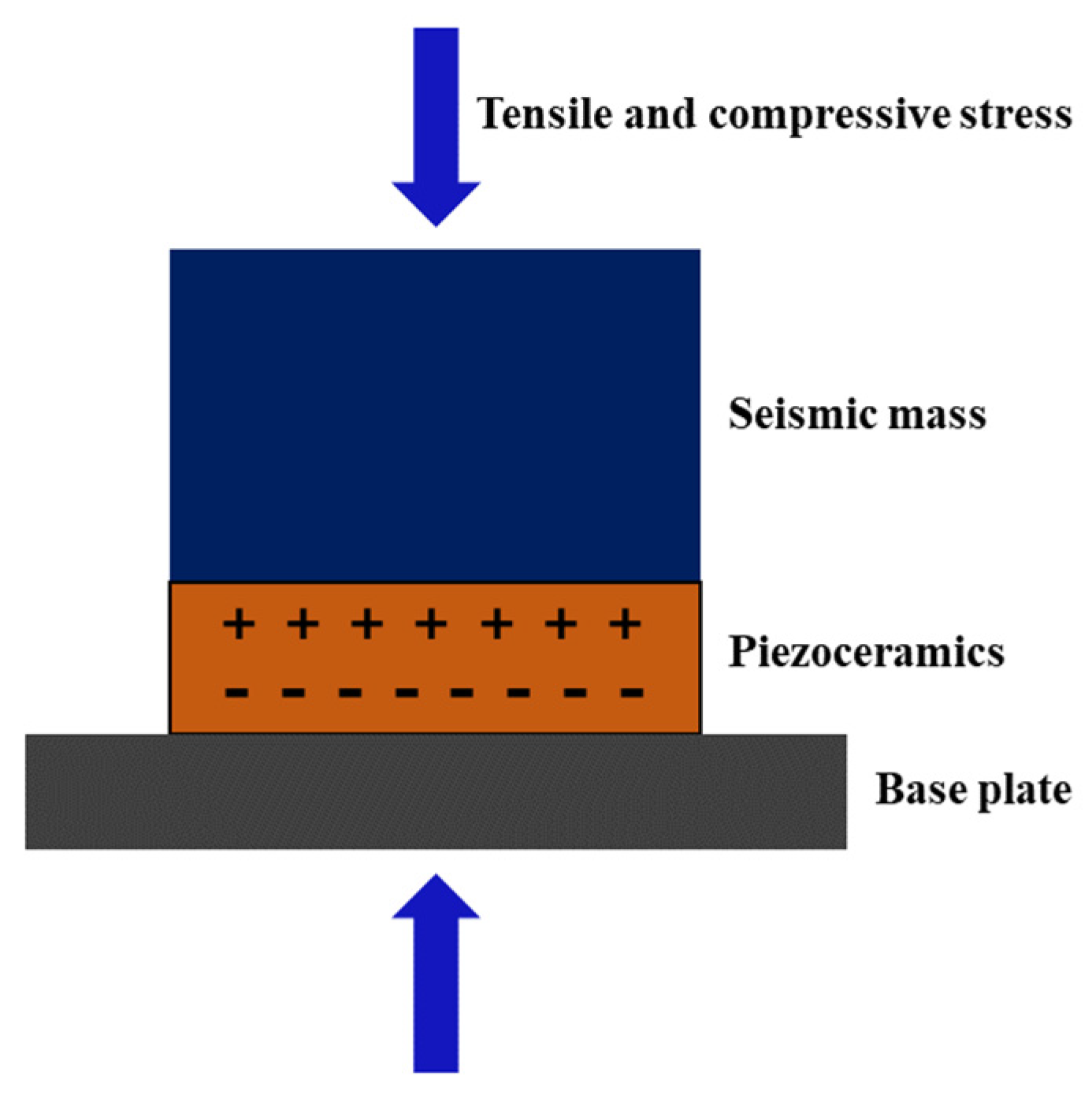
Figure 1. Schematic diagram of the operating principle of the compression accelerometer.
There are many companies that manufacture accelerometers, such as Brüel & Kjær, Gulton Manufacturing, Kistler, PCB, Endevco and others. Structurally, it has gone through changes and advancements from compression type to shear type (planar shear, triangular shear, annular shear, and orthogonal shear). In terms of electrical performance, piezoelectric accelerometer technology has progressed from a high-impedance charge output type (PE) to a low-impedance voltage output type (IEPE). Currently, most piezoelectric accelerometers have built-in charge-voltage converter circuits and operate with low-impedance voltage output. Their conventional low-frequency response is typically 0.5 Hz, making them suitable for most shock and vibration measurement applications. Despite the mature development of piezoelectric acceleration sensors, innovation in the means of piezoelectric accelerometer design has become a pressing issue as the application areas continue to expand.
2. Structure of Piezoelectric Accelerometers
2.1. Compression Mode Piezoelectric Accelerometer
A compression mode accelerometer has a simple structure, strong rigidity, high output sensitivity, and other characteristics that make it suitable for dynamic measurement and widely used in vibration measurement. The structure of the center compression mode accelerometer is shown in Figure 5a, which mainly consists of a mass block, a fixed nut, a piezoelectric element, and a base. In order to maintain the stability of the accelerometer, a central pillar is added at the central axis of the base to connect the mass block, the piezoelectric element, and the base together. The maximum intrinsic frequency can be obtained when the mass of the mass block is comparable to the mass of the base. The piezoelectric element–spring–mass system is fixed on a central cylinder connected to the accelerometer base using the thickness vibration mode [13]. This structure is very stable and has high resonant frequencies. However, since the piezoelectric element is bolted to the base, any dynamic changes in the base, such as base strain or thermal expansion, can cause stress changes on the piezoelectric element and output the wrong signal. In order to reduce the effects of base strain and thermal instability on the object under test, the compression type can also be designed as an inverted center compression type or isolated base compression type structure. The isolated base compression type is designed with a mechanical isolation slot between the base and the piezoelectric element. A hollow inertial mass block is employed as a thermal barrier to effectively reduce the wrong output due to base strain and transient temperature, as shown in Figure 2b [2].
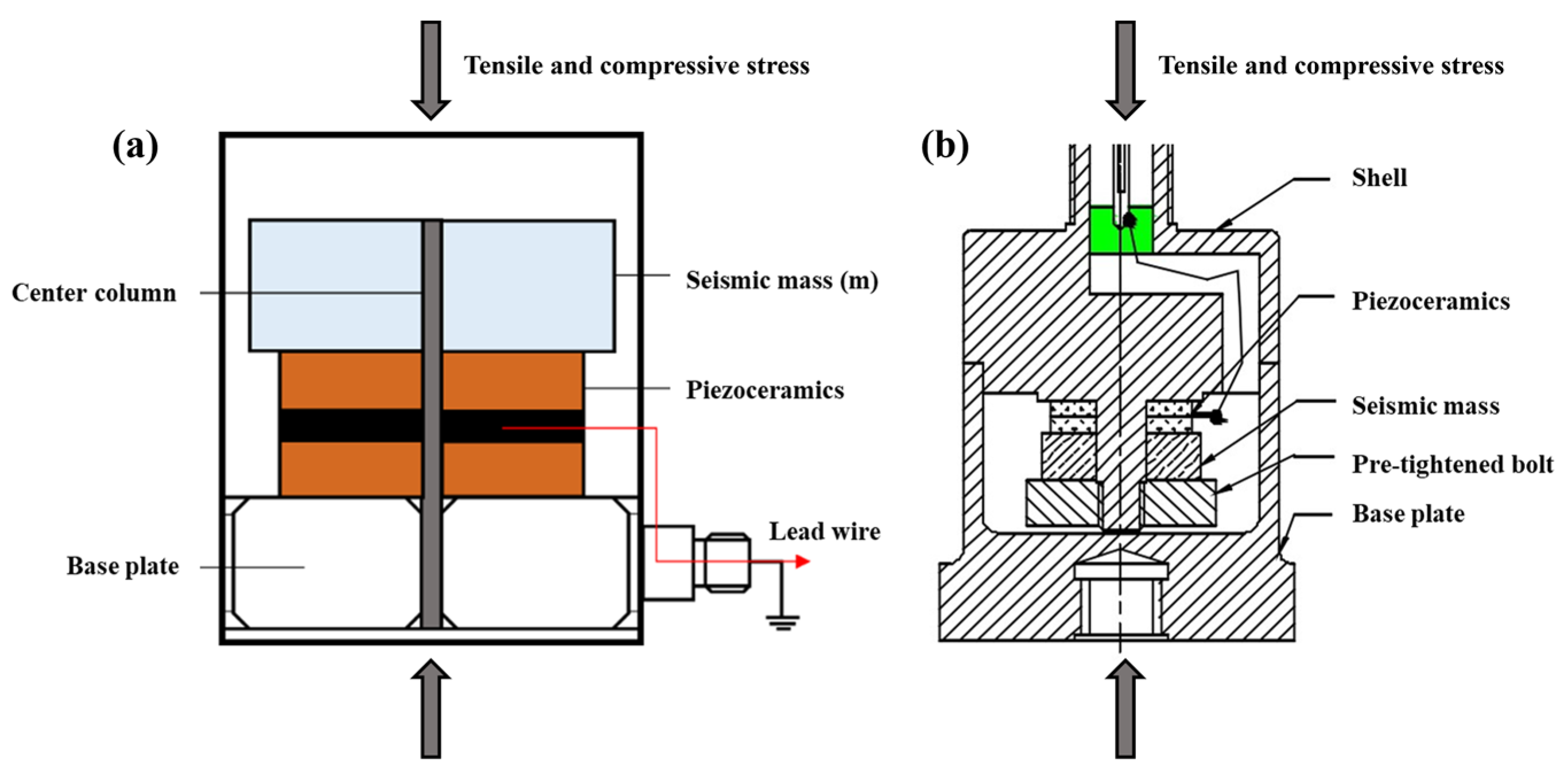
Figure 2. (a) Center compression accelerometer structure; (b) inverted compression type piezoelectric accelerometer structure.
2.2. Shear-Mode Piezoelectric Accelerometer
The piezoelectric element of the center compression type accelerometer is in complete contact with the base, and the vibration or temperature change of the base will affect the piezoelectric effect of the piezoelectric element and make the sensor system generate errors. In shear accelerometers, the piezoelectric element is not in contact with the base, thus avoiding the influence of the base on the piezoelectric element. Compared to compression mode accelerometers, shear-mode accelerometers are more complex to machine and assemble, but their lateral sensitivity and environmental sensitivity are smaller than compression ones [1]. The structure of a shear-mode accelerometer is shown in Figure 3a. The shear-type structure sandwiches the piezoelectric element between the central column and the inertial mass block in a fixed manner, and the preload bolt provides the preload force required to form a rigid structure with resistance to transient temperature and base strain effects. Under acceleration, the mass block exerts a shear stress on the piezoelectric element. The sensitive axis direction is vertical, and the sensitivity is maximum in this direction. Ideally, the sensitivity in the orthogonal direction is zero. However, due to structural tolerances or the cross-sensitivity of the crystal itself, commercial sensors have sensitivity in the direction perpendicular to the sensitive axis, making them cross-sensitive (a few percent of the sensitive axis sensitivity). The lateral sensitivity of piezoelectric accelerometers is generally not allowed to exceed 5%, and the influencing factors include the design of the mechanical structure of the sensor, the processing accuracy of the parts, and the accuracy of the assembly process. In order to reduce the lateral sensitivity, the overall structure should be designed to ensure that the overall structure is symmetrical on the sensitive axis [11].
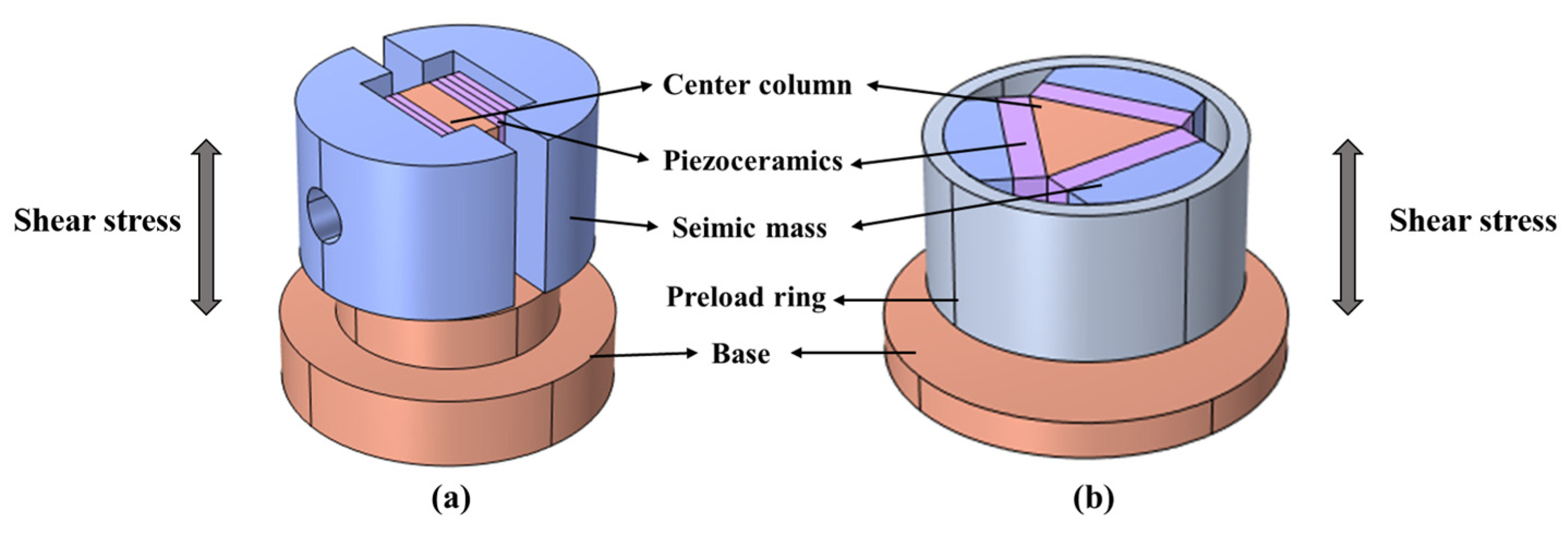
Figure 3. (a) Planar shear accelerometer; (b)triangular shear accelerometer structure schematic.
In addition to the planar shear mode, there are triangular shear-mode structures (Figure 3b) as well as annular shear-mode structures. The three mass-spring systems in the triangular shear-mode structure are tightened with a preload ring to form a complete spring–mass system. The triangular shear structure has the highest sensitivity-to-mass ratio and a relatively high resonant frequency compared to other structure types. The overall spring–mass system does not contain adhesives or bolts, which ensures the desired performance and reliability. A cylindrical center column and a circular piezoelectric element are used in the ring shear-mode structure. The curved mass block, which fits snugly into the piezoelectric element, is held in place with a preload ring, and this structure is often used to measure shock acceleration [14].
2.3. Bending Accelerometer
The bending accelerometer structure is shown in Figure 4. When the accelerometer senses the vibration, the piezoelectric element is bent and deformed under its own inertial force, and the charge signal is output. The bending structure is insensitive to lateral vibration and has excellent thermal stability, but its shock resistance is poor, and it is usually used as a low vibration magnitude accelerometer for structural analysis testing [15][16].
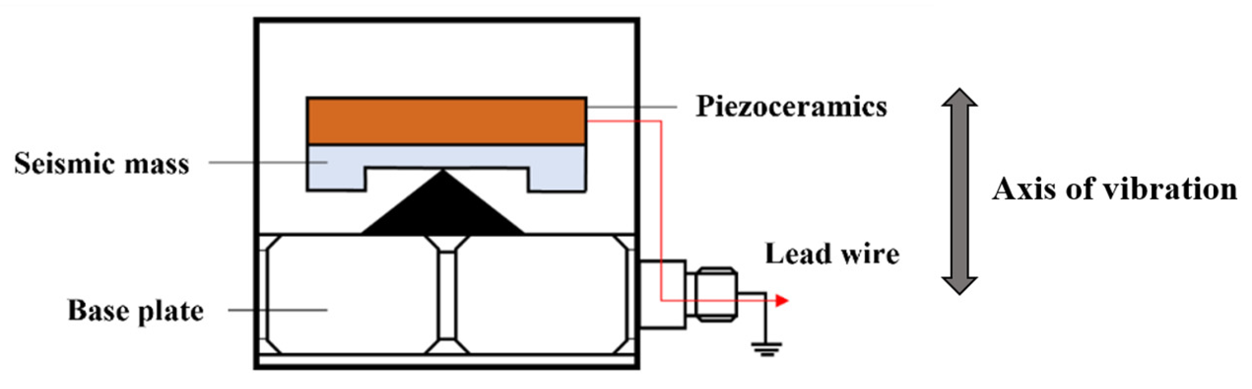
Figure 4. Bending accelerometer structure schematic (the red arrow indicates the direction of charge output).
2.4. IEPE Accelerometer
In a conventional piezoelectric accelerometer, the charge generated by the piezoelectric element is transmitted through a cable to an amplifier, and the signal is acquired by a data acquisition card. The capacitive loading of the cable increases the noise and requires the use of expensive low-noise cables [17]. Piezoelectric accelerometers with integral electronics (IEPE) integrate piezoelectric transducers and electronic circuitry in a shielded housing and are primarily used to measure response characteristics in the frequency range of 1 Hz to 19 kHz and even below. IEPE accelerometers have the advantages of a high signal-to-noise ratio, wide frequency response, low output impedance, high sensitivity, insensitivity to electromagnetic interference, and the ability to be implemented in miniature designs [18].
The IEPE accelerometer structure is mainly composed of two parts: the piezoelectric sensor and the signal debugging circuit, and its working principle diagram is shown in Figure 5. In dynamic acceleration measurements, the IEPE accelerometer operates in the frequency range below the resonant frequency of the PE sensor. In the normal operating frequency range, the PE sensor is essentially a capacitive signal source with high impedance. Charge amplifiers and voltage amplifiers are two basic types of internal electronic circuits in IEPE accelerometers, whose main function is to convert the charge signal generated by the PE sensor into a voltage output signal [19][20]. Typically, the amplifier circuit consists of an input stage based on a field effect transistor (FET) and an output stage based on a bipolar junction transistor (BJT). The amplifier converts the high-impedance charge signal generated by the PE sensor into a low-impedance voltage signal that can be transmitted over long distances. The low output impedance means that the output signal can be transmitted to the signal conditioning circuit using low-cost conventional coaxial or other types of shielded cable [21][22][23][24].
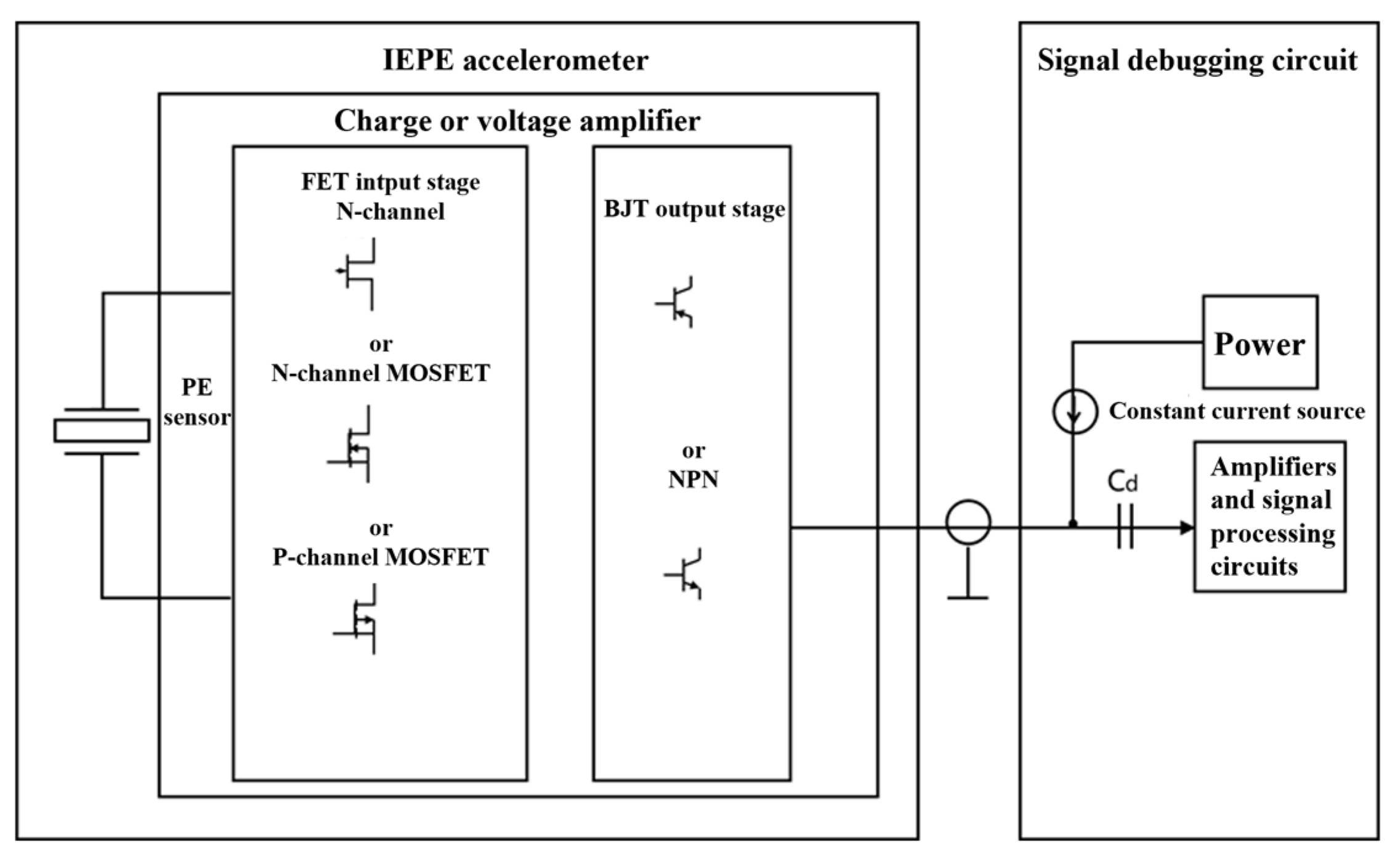
Figure 5. IEPE accelerometer working principal diagram.
2.5. MEMS Type Piezoelectric Accelerometer
Micro-electro-mechanical systems (MEMS) are traditional semiconductor manufacturing and microfabrication technologies. MEMS accelerometers have many advantages compared with traditional accelerometers, such as small size, light weight, low energy consumption, and so on. They have received wide attention, and their principle schematic diagram is shown in Figure 6 [25]. MEMS accelerometers can be divided into piezoresistive, capacitive, piezoelectric, thermal conductivity, and other types according to the different detection methods. Among them, MEMS piezoelectric accelerometers have the following advantages over other types of accelerometers: A wide dynamic range, wide frequency range, and easy integration into existing measurement systems, which are widely used in engine vibration analysis, auditory devices, and other fields. At the same time, there are some shortcomings: no steady-state response, high output impedance, and high requirements for detection circuits [26].
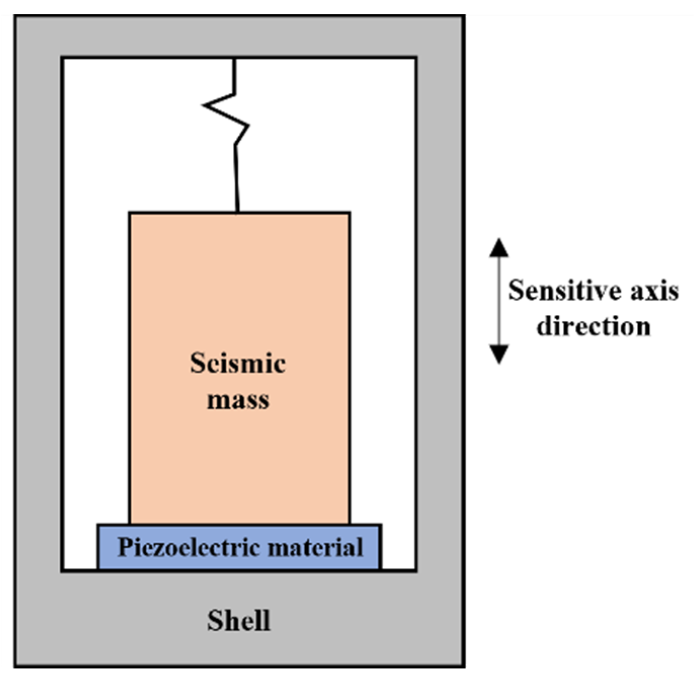
Figure 6. Schematic of piezoelectric MEMS accelerometer.
The piezoelectric MEMS accelerometer is formed by using the piezoelectric effect, and the structure consists of a mass block connected to a piezoelectric element and connected to the shell by an elastic structure. The working principle is that the mass block is displaced under the excitation of acceleration, which leads to the deformation of the piezoelectric film [27]. The piezoelectric film generates an electric charge output due to the stress, which is amplified by the amplifier and collected by the computer control system to detect the acceleration of the object to be measured [28]. There are three common structures of piezoelectric accelerometers (Figure 7a): Four-armed beam type, ring type, and hexagonal structure type. Figure 7b shows the section view of an aluminum nitride (AlN)-based MEMS piezoelectric accelerometer [29].
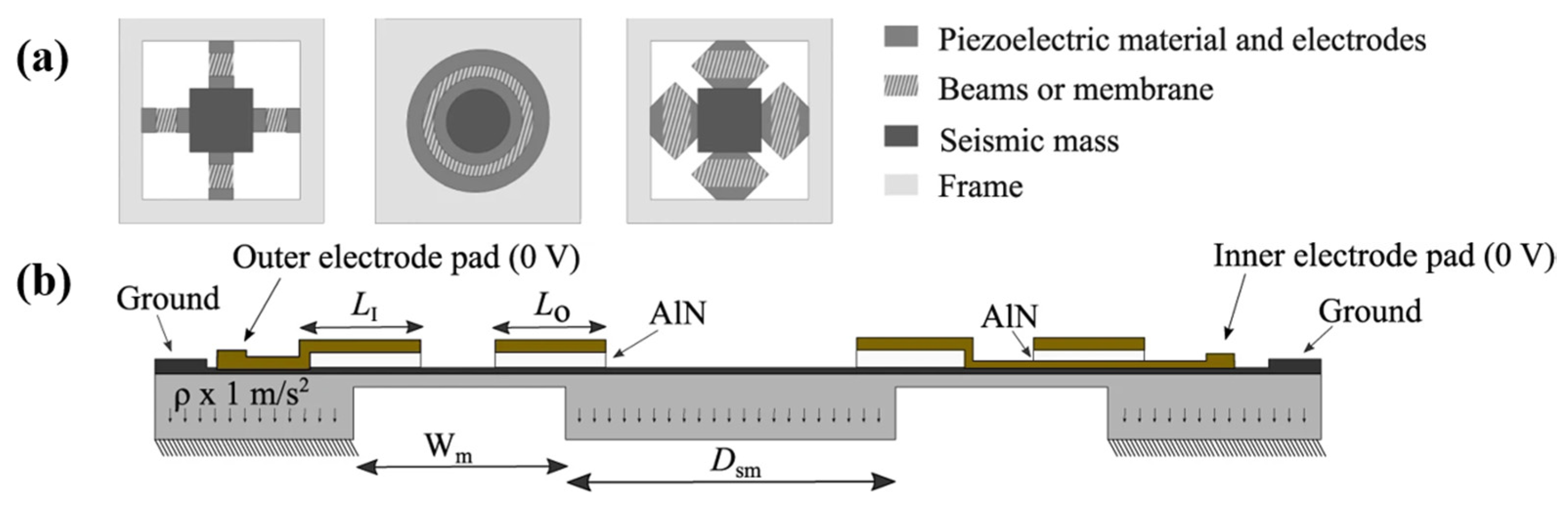
Figure 7. (a) Three common structures of MEMS piezoelectric accelerometers; (b) the section view of a piezoelectric accelerometer [29].
The advantages and disadvantages of the different structure types of piezoelectric accelerometers are summarized in the Table 1.
Table 1. Advantages and disadvantages of different structure types of piezoelectric accelerometers.
| Structure of Accelerometer | Advantages | Disadvantages | Application |
|---|---|---|---|
| Compression accelerometers | Simple structure, easy processing, high resonant frequency | Large noise signal, sensitivity affected by thermal expansion and stress of the base, weak anti-interference signal capability | Impact tests |
| Shear accelerometers | Piezoelectric wafer is not in contact with the base, low noise signal, high strain resistance, and easy to miniaturize | Complex structure | Hydrophone and microseismic monitoring |
| Bending accelerometers | Small volume, light weight, good thermal stability, high sensitivity, simple damping control | Narrow frequency response range, poor shock resistance, temperature changes easily lead to signal drift | Earthquake monitoring, vehicle tracking, and geophysical exploration |
| IEPE Accelerometers | Low noise, wide dynamic range, use of conventional cables, insensitive to electromagnetic interference (EMI), with a self-test function for working status | Requires power supply | Wind turbines, low-frequency, and low-noise environments |
| Piezoelectric MEMS accelerometers | Small size, light weight, low energy consumption, high sensitivity, wide dynamic range | Does not have static sensitivity, no steady-state response, high output impedance, high requirements for the detection circuit | Wearable applications |
References
- Pyo, S.; Kim, J.; Kim, H.; Roh, Y. Development of Vector Hydrophone Using Thickness–Shear Mode Piezoelectric Single Crystal Accelerometer. Sens. Actuator A Phys. 2018, 283, 220–227.
- Walter, P.L. The History of the Accelerometer. Sound Vib. 1997, 31, 84–92.
- Kasten, K.; Amelung, J.; Mokwa, W. CMOS-compatible capacitive high temperature pressure sensors. Sens. Actuator A Phys. 2000, 85, 147–152.
- Zhang, L.; Yu, J.; Liu, H. Conditioning circuit for precise SiC capacitive pressure sensors. In Proceedings of the IEEE Conference on Industrial Electronics and Applications (ICIEA 2011), Beijing, China, 21–23 June 2011.
- Aydemir, A.; Terzioglu, Y.; Akin, T. A new design and a fabrication approach to realize a high performance three axes capacitive MEMS accelerometer. Sens. Actuators A Phys. 2016, 244, 324–333.
- Chaehoi, A.; Latorre, L.; Nouet, P.; Baglio, S. Piezoresistive CMOS beams for inertial sensing. In Sensors; IEEE: Piscataway, NJ, USA, 2003.
- Xu, Y.; Zhao, L.; Jiang, Z.; Ding, J.; Xu, T. Analysis and design of a novel piezoresistive accelerometer with axially stressed selfsupporting sensing beams. Sens. Actuator A Phys. 2016, 247, 1–11.
- Wang, P.; Zhao, Y.; Tian, B.; Liu, Y.; Wang, Z.; Li, C.; Zhao, Y. A piezoresistive micro accelerometer with high frequency response and low transvers effect. Meas. Sci. Technol. 2017, 28, 015103.
- Comi, C.; Corigliano, A.; Langfelder, G.; Longoni, A.; Tocchio, A.; Simoni, B. A New Two-beam Differential Resonant Micro Accelerometer; IEEE: Piscataway, NJ, USA, 2009; pp. 158–163.
- Comi, C.; Corigliano, A.; Langfelder, G.; Longoni, A.; Tocchio, A.; Simoni, B. A high sensitivity uniaxial resonant accelerometer. IEEE. 2010, 33, 260–263.
- Zotov Sergei, A.; Simon Brenton, R.; Trusov Alexander, A.; Shkel, A.M. High Quality Factor Resonant MEMS Accelerometer with Con tinuous Thermal Compensation. IEEE Sens. J. 2015, 15, 5045–5052.
- Shi, Y.; Jiang, S.; Liu, Y.; Wang, Y.; Qi, P. Design and Optimization of a Triangular Shear Piezoelectric Acceleration Sensor for Microseismic Monitoring. Geofluids 2022, 2022, 3964502.
- Choy, S.H.; Wang, X.X.; Chan, H.L.W.; Choy, C.L. Study of Compressive Type Accelerometer Based on Lead-Free BNKBT Piezoceramics. Appl. Phys. A Mater. Sci. Process 2006, 82, 715–718.
- Levinzon, F. Piezoelectric Transducers Used for Piezoelectric Accelerometers with Integral Electronics. In Piezoelectric Accelerometers with Integral Electronic; Springer: Cham, Switzerland, 2015.
- Kollias, A.T.; Avaritsiotis, J.N. A Study on the Performance of Bending Mode Piezoelectric Accelerometers. Sens. Actuators A Phys. 2005, 121, 434–442.
- Haruo, T.A. Analysis of Piezoelectric Bending Accelerometer Using the Equivalent Circuit. Jpn. J. Appl. Phys. 1996, 35, 3035–3037.
- Jonscher, C.; Hofmeister, B.; GrieBmann, T.; Rolfes, R. Very Low Frequency IEPE Accelerometer Calibration and Application to a Wind Energy Structure. Wind. Energy Sci. 2022, 7, 1053–1067.
- Niskanen, A.; Tuononen, A.J. Three Three-Axis IEPE Accelerometers on the Inner Liner of a Tire for Finding the Tire-Road Friction Potential Indicators. Sensors 2015, 15, 19251–19263.
- Wlodkowski, P.A.; Deng, K.; Kahn, M. The development of high-sensitivity, low-noise accelerometers utilizing single crystal piezoelectric materials. Sens. Actuators A. 2001, 90, 125–131.
- Gabriielson, T.B. Mechanical-Thermal noise in micromachined acoustic and vibration sensors. IEEE Trans. Electron. Devices 1993, 40, 903–909.
- Peng, C.C.; Tsan, L.G. IEPE Accelerometer Fault Diagnosis for Maintenance Management System Information Integration in a Heavy Industry. J. Ind. Inf. Integr. 2020, 17, 100120.
- Boser, B.E.; Howe, R.T. Surface micromachined accelerometers. IEEE J. Solid-State Circuits 1996, 31, 366–375.
- Tavakoli, M.; Sarpeshkar, R. An offset Canceling low Noise lock in architecture for capacitive sensing. IEEE J. Solid-State Circuits 2003, 38, 244–253.
- Chau, H.; Wise, K.D. Noise due to brownian motion in ultrasensitive solid Statepreasure sensors. IEEE Trans. Electron. Devices 1987, 24, 859–865.
- Li, X.; Yang, H.; Bao, M.; Carrell, K.; Chen, Y.; Zhao, G.; Awakura, Y.; Ebata, A.; Kondo, Y.; De Reus, R.; et al. Fabrication and Characterization of a Piezoelectric Accelerometer. J. Micromech. Microeng. 1999, 9, 123.
- Dong, Y.; Zwahlen, P.; Nguyen, A.M.; Frosio, R.; Rudolf, F. Ultra-high precision MEMS accelerometer. In Proceedings of the 2011 16th International Solid-State Sensors, Actuators and Microsystems Conference, Beijing, China, 5–9 June 2011; pp. 695–698.
- Wang, L.P.; Wolf, R.A.; Wang, Y.; Deng, K.K.; Zou, L.; Davis, R.J.; Trolier-McKinstry, S. Design, fabrication, and measurement of high-sensitivity piezoelectric microelectromechanical systems accelerometers. J. Microelectromechanical Syst. 2003, 12, 433–439.
- Gerfers, F.; Kohlstadt, M.; Bar, H.; He, M.-Y.; Manoli, Y.; Wang, L.-P. Sub-μg ultra-low-noise MEMS accelerometers based on CMOS-compatible piezoelectric AlN thin films. In Proceedings of the Solid-State Sensors, Actuators and Microsystems Conference, Lyon, France, 10–14 June 2007; pp. 1191–1194.
- Gesing, A.L.; Alves, F.D.P.; Paul, S.; Cordioli, J.A. On the Design of a MEMS Piezoelectric Accelerometer Coupled to the Middle Ear as an Implantable Sensor for Hearing Devices. Sci. Rep. 2018, 8, 3920.
More
Information
Subjects:
Materials Science, Ceramics
Contributors
MDPI registered users' name will be linked to their SciProfiles pages. To register with us, please refer to https://encyclopedia.pub/register
:
View Times:
4.6K
Revisions:
2 times
(View History)
Update Date:
28 Sep 2023
Table of Contents


Notice
You are not a member of the advisory board for this topic. If you want to update advisory board member profile, please contact office@encyclopedia.pub.
OK
Confirm
Only members of the Encyclopedia advisory board for this topic are allowed to note entries. Would you like to become an advisory board member of the Encyclopedia?
Yes
No
${ textCharacter }/${ maxCharacter }
Submit
Cancel
Back
Comments
${ item }
|
${ item.createdUser.fullName }
${ item.createdAt }
${ item.vote }
${ item.reply }
Delete
${ reply.createdUser.fullName }
${ reply.createdAt }
${ reply.vote }
Delete
There is no reply to this comment~
${ item.replyTextCharacter }/${ item.replyMaxCharacter }
Submit
Cancel
More
No more~
There is no comment~
${ textCharacter }/${ maxCharacter }
Submit
Cancel
${ selectedItem.replyTextCharacter }/${ selectedItem.replyMaxCharacter }
Submit
Cancel
Confirm
Are you sure to Delete?
Yes
No