 +1 credit
| Version | Summary | Created by | Modification | Content Size | Created at | Operation |
|---|---|---|---|---|---|---|
| 1 | Mehdi Moradian | -- | 1608 | 2023-09-05 11:34:28 | | | |
| 2 | Fanny Huang | -24 word(s) | 1584 | 2023-09-06 08:51:26 | | |
Video Upload Options
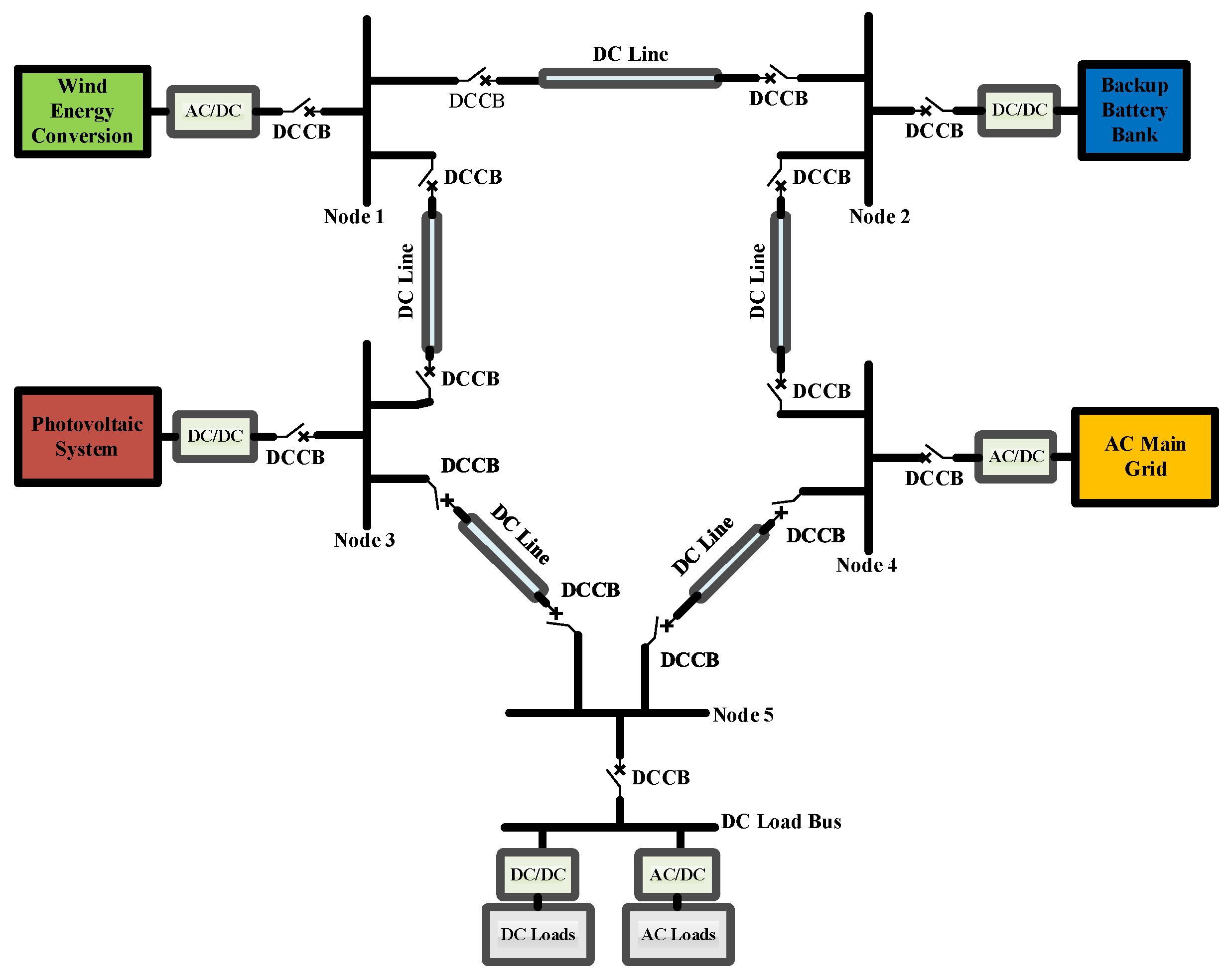
While traditional AC mechanical circuit breakers can protect AC circuits, many other DC power distribution technologies, such as DC microgrids (MGs), yield superior disruption performance, e.g., faster and more reliable switching speeds. However, novel DC circuit breaker (DCCB) designs are challenging due to the need to quickly break high currents within milliseconds, caused by the high fault current rise in DC grids compared to AC grids. In DC grids, the circuit breaker must not provide any current crossing and must absorb surges, since the arc is not naturally extinguished by the system. Additionally, the DC breaker must mitigate the magnetic energy stored in the system inductance and withstand residual overvoltages after current interruption. These challenges require a fundamentally different topology for DCCBs, which are typically made using solid-state semiconductor technology, metal oxide varistors (MOVs), and ultra-fast switches.
1. Introduction
| Description | Schneider Electric | Eaton | Siemens | ABB | LS |
|---|---|---|---|---|---|
| Model | Power PacT JDC | CJGPVS, CKDPV | HDGD | SACE Emax | Susol |
| Rated current | 30~1200 A | 150~3000 A | 50~1600 A | Up to5000 A | 16~1600 A |
| Performance voltage | 500 VDC | 600~1000 VDC | 600 VDC | 250~1000 VDC | 500–1500 VDC |
| Breaking capacity | 20 up to 50 KA | 1.5 up to 42 KA | 42 KA | 65 KA | 20 up to 50 KA |
| Ambient conditions | −10 to 60 °C | −40 to 70 °C | −25 to 70 °C | −40 to 70 °C | −25 to 55 °C |
| Operation time | ≤30 ms | 1 ms | 70–300 ms | ≤70 ms | ≤40 ms |
2. Design Improvements of DCCBs for DC Microgrid Application
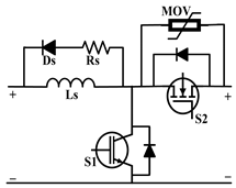
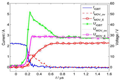
2.1. MOV-Based DCCBs
| Description | Topology 1 [28] | Topology 2 [29] | Topology 3 [30] |
|---|---|---|---|
| Proposed Model | 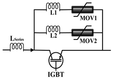 |
 |
 |
| Model Verification |
 |
 |
 |
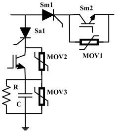
| Technique | Separated MOV | Ground Clamping | MC FCL |
| Technology | MOV-IGBT | MOV-MOSFET, IGBT | MOV-IGBT |
| Vdc/Idc | 30 v/2.5 A | 400 v/4 A | 500 v/380 A |
| Response Time | 0.4 µs | 50 ms | 1.8 ms |
| Number of Passive Components |
4 | 6 | 8 |
| Number of Active Components |
1 | 2 | ≥4 |
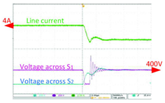
2.2. Capacitor-Based DCCBs
| Description | Topology 1 [33] | Topology 2 [34] | Topology 3 [35] |
|---|---|---|---|
| Proposed Model | 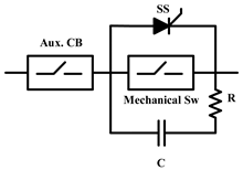 |
 |
 |
| Model Verification |
 |
 |
 |
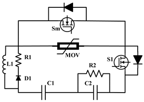
| Technique | A/C Circuit | VI- PMA | Soft-switched |
| Technology | Cap-IGBT | Cap-IGBT | Cap-MOSFET |
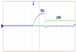
| Vdc/Idc | 283 v/43.5 A | 750 v/300 A | 240 v/50 A |
| Response Time | 15 ms | 9.6 ms | 20 ms |
| Number of Passive Components |
2 | 7 | 12 |
| Number of Active Components |
3 | 5 | 5 |
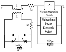
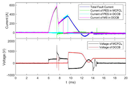
2.3. Hybrid MOV–Cap DCCBs
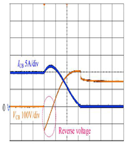
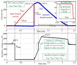
| Description | Topology 1 [47][48] | Topology 2 [49] | Topology 3 [50] |
|---|---|---|---|
| Proposed Model | 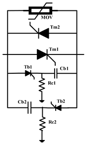 |
 |
 |
| Model Verification |
 |
 |
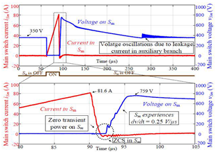 |
| Technique | AT CB-DCCB | TIM-Pack | LCC-AIC |
| Technology | MOV–Cap Thyristor | MOV–Cap Thyristor-IGBT | MOV–Cap SiC MOSFET |
| Vdc/Idc | 150 v/10 A | 600 v/145 A | 350 v/90 A |
| Response Time | 1.6 ms | 6 µs | 4 µs |
| Number of Passive Components |
5 | 5 | 9 |
| Number of Active Components |
4 | 4 | 2 |
References
- Rezk, H.; Ghoniem, R.M.; Ferahtia, S.; Fathy, A.; Ghoniem, M.M.; Alkanhel, R. A Comparison of Different Renewable-Based DC Microgrid Energy Management Strategies for Commercial Buildings Applications. Sustainability 2022, 14, 16656.
- Lotfi, H.; Khodaei, A. Hybrid AC/DC microgrid planning. Energy 2017, 118, 37–46.
- Papari, B.; Edrington, C.S.; Bhattacharya, I.; Radman, G. Effective Energy Management of Hybrid AC–DC Microgrids with Storage Devices. IEEE Trans. Smart Grid 2019, 10, 193–203.
- Vuyyuru, U.; Maiti, S.; Chakraborty, C. Active Power Flow Control Between DC Microgrids. IEEE Trans. Smart Grid 2019, 10, 5712–5723.
- Jain, D.; Saxena, D. Comprehensive review on control schemes and stability investigation of hybrid AC-DC microgrid. Electr. Power Syst. Res. 2023, 218, 109182.
- Baidya, S.; Nandi, C. A comprehensive review on DC Microgrid protection schemes. Electr. Power Syst. Res. 2022, 210, 108051.
- Montoya, R.; Poudel, B.P.; Bidram, A.; Reno, M.J. DC microgrid fault detection using multiresolution analysis of traveling waves. Electr. Power Energy Syst. 2022, 135, 107590.
- Bayati, N.; Balouji, E.; Baghaee, H.R.; Hajizadeh, A.; Soltani, M.; Lin, Z.; Savaghebi, M. Locating high-impedance faults in DC microgrid clusters using support vector machines. Appl. Energy 2022, 308, 118338.
- Ibrahim, M.H.; Badran, E.A.; Abdel-Rahman, M.H. On the DC Microgrids Protection Challenges, Schemes, and Devices—A Review. In DC Microgrids: Advances, Challenges, and Applications; Wiley: Hoboken, NJ, USA, 2022.
- Zhang, Q.; Hu, W.; Liu, Y.; Zhang, H.; Wang, H. A novel smooth switching control strategy for multiple photovoltaic converters in DC microgrids. J. Power Electron. 2022, 22, 163–175.
- Available online: https://new.abb.com/low-voltage/products/circuit-breakers (accessed on 27 March 2023).
- Available online: https://www.se.com/ww/en/product-range/44215156-compact-for-dc-networks-new-generation (accessed on 27 March 2023).
- Available online: https://www.eaton.com/nz/en-gb/products/electrical-circuit-protection/circuit-breakers.html (accessed on 27 March 2023).
- Available online: https://www.siemens.com/global/en/products/energy/low-voltage/components/sentron-protection-devices.html (accessed on 27 March 2023).
- Available online: https://www.ls-electric.com/products/category/Smart_Power_Solution/DC_Component (accessed on 27 March 2023).
- Huo, Q.; Xiong, J.; Zhang, N.; Guo, X.; Wu, L.; Wei, T. Review of DC circuit breaker application. Electr. Power Syst. Res. 2022, 209, 107946.
- Corzine, K.A. Circuit Breaker for DC Micro Grids. In Proceedings of the IEEE First International Conference on DC Microgrids (ICDCM), Atlanta, GA, USA, 7–10 June 2015.
- Maqsood, A.; Corzine, K.A. DC Microgrid Protection: Using the Coupled-Inductor Solid-State Circuit Breaker. IEEE Electrif. Mag. 2016, 4, 58–64.
- Bayati, N.; Baghaee, H.R.; Savaghebi, M.; Hajizadeh, A.; Soltani, M.N.; Lin, Z. DC Fault Current Analyzing, Limiting, and Clearing in DC Microgrid Clusters. Energies 2021, 14, 6337.
- Srivastana, C.; Tripathy, M. DC microgrid protection issues and schemes: A critical review. Renew. Sustain. Energy Rev. 2021, 115, 111546.
- Beheshtaein, S.; Cuzner, R.M.; Forouzesh, M.; Savaghebi, M.; Guerrero, J.M. DC microgrid protection: A comprehensive review. IEEE J. Emerg. Sel. Top. Power Electron. 2019, 12.
- Smith, M.W.; McCormik, M.D. Transient Voltage Suppression Manual, 3rd ed.; General Electric: Boston, MA, USA, 1982.
- Zhang, Z.J.; Bosworth, M.; Xu, C.; Rockhill, A.; Zeller, P.; Saeedifard, M.; Graber, L.; Steurer, M. Lifetime-Based Selection Procedures for DC Circuit Breaker Varistors. IEEE Trans. Power Electron. 2022, 37, 13525–13537.
- Xu, C.; Rockhill, A.; Zhang, Z.J.; Bosworth, M.; Saeedifard, M.; Steurer, M.; Zeller, P.; Graber, L. Evaluation Tests of Metal Oxide Varistors for DC Circuit Breakers. IEEE Open Acc. J. Power Energy 2022, 9, 254–264.
- Rachi, M.R.K.; Husain, I. Main Breaker Switching Control and Design Optimization for A Progressively Switched Hybrid DC Circuit Breaker. In Proceedings of the 2020 IEEE Energy Conversion Congress and Exposition (ECCE), Detroit, MI, USA, 11–15 October 2020.
- Kularatna, N.; Ross, A.S.; Fernando, J.; James, S. Design of Transient Protection Systems-Including Supercapacitor Based Design Approaches for Surge Protectors; Elsevier: Amsterdam, The Netherlands, 2019; ISBN 978-0-12-811664-7.
- Ravi, L.; Zhang, D.; Qin, D.; Zhang, Z.; Xu, Y.; Dong, D. Electronic MOV-Based Voltage Clamping Circuit for DC Solid-State Circuit Breaker Applications. IEEE Trans. Power Electron. 2022, 37, 7561–7565.
- Magnusson, J.; Saers, R.; Liljestrand, L.; Engdahl, G. Separation of the Energy Absorption and Overvoltage Protection in Solid-State Breakers by the Use of Parallel Varistors. IEEE Trans. Power Electron. 2014, 29, 2715–2722.
- Pang, T.; Manjrekar, M.D. A Surge Voltage Free Solid-State Circuit Breaker with Current Limiting Capability. In Proceedings of the IEEE Applied Power Electronics Conference and Exposition (APEC), Phoenix, AZ, USA, 14–17 June 2021.
- Gan, Z.; Yu, Z.; Nie, Z.; Qu, L.; Yan, X.; Huang, Y.; Zeng, R.; Gu, H. Coordinated DC Interruption Method Based on Magnetic Coupling Current-Limiting and Dissipation. IEEE Trans. Power Electron. 2023, 38, 2398–2407.
- Wu, T.; Wang, Z.; Fang, C.; Liu, S. Research on current limiting solid state circuit breaker for DC microgrid. Electr. Power Syst. Res. 2022, 209, 107950.
- Tracy, L.; Sekhar, P.K. Design and Testing of a Low Voltage Solid-State Circuit Breaker for a DC Distribution System. Energies 2020, 13, 338.
- Sen, S.; Mehraeen, S. Improving Low-Voltage DC Circuit Breaker Performance Through an Alternate Commutating Circuit. IEEE Trans. Ind. Appl. 2019, 55, 6127–6136.
- Kim, D.; Kim, S. Design and analysis of hybrid DC circuit breaker for LVDC grid systems. J. Power Electron. 2021, 21, 1395–1405.
- Rahimpour, S.; Husev, O.; Vinnikov, D. Design and Analysis of a DC Solid-State Circuit Breaker for Residential Energy Router Application. Energies 2022, 15, 9434.
- Li, W.; Wang, Y.; Wu, X.; Zhang, X. A Novel Solid-State Circuit Breaker for On-Board DC Microgrid System. IEEE Trans. Ind. Electron. 2019, 66, 5715–5723.
- Zhou, Z.Z.; Jiang, J.G.; Ye, S.; Liu, C.; Zhang, D. A Γ-source circuit breaker for DC microgrid protection. IEEE Trans. Ind. Electron. 2021, 68, 2310–2320.
- Diao, X.; Liu, F.; Song, Y.; Xu, M.; Zhuang, Y.; Zha, X. An Integral Fault Location Algorithm Based on a Modified T-Source Circuit Breaker for Flexible DC Distribution Networks. IEEE Trans. Power Del. 2021, 36, 2861–2871.
- Savaliya, S.G.; Fernandes, B.G. Analysis and experimental validation of bidirectional Z-source DC circuit breakers. IEEE Trans. Ind. Electron. 2020, 67, 4613–4622.
- Diao, X.; Liu, F.; Zhuang, Y.; Pan, S.; Zha, X. A Bidirectional Efficient Circuit Breaker with Automatic and Controllable Shutoff Functions for DC Distribution Network. IEEE Trans. Ind. Electron. 2023, 70, 7988–7999.
- Ryan, D.J.; Torresan, H.D.; Bahrani, B. A Bidirectional Series Z-Source Circuit Breaker. IEEE Trans. Power Electron. 2018, 33, 7609–7621.
- Ugalde-Loo, C.E.; Wang, Y.; Wang, S.; Ming, W.; Liang, J.; Li, W. Review on Z-Source Solid State Circuit Breakers for DC Distribution Networks. CSEE J. Power Energy Syst. 2023, 9, 15–27.
- Sun, Y.; Fan, Y.; Hou, J. Capacitor commutation type DC circuit breaker with fault character discrimination capability. J. Power Electron. 2023, 23, 1016–1027.
- Yu, Z.; Yan, X.; Zhang, X.; Qu, L.; Gan, Z.; Huang, Y. The Design and Development of a Novel 10 kV/60 kA Hybrid DC Circuit Breaker Based on Mixed Solid-State Switches. IEEE Trans. Ind. Electron. 2023, 70, 2440–2449.
- Qin, K.; Wang, S.; Ma, J.; Shu, J.; Zhang, R.; Liu, T. Thyristor-based DCCB with Reliable Fast Reclosing Protection Ability by Restoring Capacitor Polarity. IEEE Trans. Power Electron. 2023, 38, 7760–7770.
- Kheirollahi, R.; Zhao, S.; Lu, F. Fault Current Bypass-Based LVDC Solid-State Circuit Breakers. IEEE Trans. Power Electron. 2022, 37, 7–13.
- Shu, J.; Ma, J.; Wang, S.; Dong, Y.; Liu, T.; He, Z. A New Active Thyristor-Based DCCB With Reliable Opening Process. IEEE Trans. Power Electron. 2021, 36, 3617–3621.
- Marwaha, M.; Satpathi, K.; Sathik, M.H.M.; Pou, J.; Gajanayake, C.J.; Gupta, A.K.; Molligoda, D.; Surapaneni, R.K. SCR-Based Bidirectional Circuit Breaker for DC System Protection with Soft Reclosing Capability. IEEE Trans. Ind. Electron. 2023, 70, 4739–4750.
- Kheirollahi, R.; Zhao, S.; Zhang, H.; Lu, F. Fault Current Bypass-Based DC SSCB Using TIM-Pack Switch. IEEE Trans. Ind. Electron. 2023, 70, 4300–4304.
- Kheirollahi, R.; Zhao, S.; Zhang, H.; Lu, F. Fully Soft-Switched DC Solid-State Circuit Breakers. IEEE Trans. Power Electron. 2023, 38, 6750–6754.

