Your browser does not fully support modern features. Please upgrade for a smoother experience.
Submitted Successfully!
 +1 credit
Thank you for your contribution! You can also upload a video entry or images related to this topic.
For video creation, please contact our Academic Video Service.
| Version | Summary | Created by | Modification | Content Size | Created at | Operation |
|---|---|---|---|---|---|---|
| 1 | Ángel Á. Pardiñas | -- | 5380 | 2023-09-05 11:08:36 | | | |
| 2 | Rita Xu | -18 word(s) | 5362 | 2023-09-05 11:31:25 | | |
Video Upload Options
We provide professional Academic Video Service to translate complex research into visually appealing presentations. Would you like to try it?
Cite
If you have any further questions, please contact Encyclopedia Editorial Office.
Carrasco Ortega, P.; Durán Gómez, P.; Mérida Sánchez, J.C.; Echevarría Camarero, F.; Pardiñas, �.�. Battery Management System. Encyclopedia. Available online: https://encyclopedia.pub/entry/48814 (accessed on 09 July 2026).
Carrasco Ortega P, Durán Gómez P, Mérida Sánchez JC, Echevarría Camarero F, Pardiñas ��. Battery Management System. Encyclopedia. Available at: https://encyclopedia.pub/entry/48814. Accessed July 09, 2026.
Carrasco Ortega, Pablo, Pablo Durán Gómez, Julio César Mérida Sánchez, Fernando Echevarría Camarero, Ángel Á. Pardiñas. "Battery Management System" Encyclopedia, https://encyclopedia.pub/entry/48814 (accessed July 09, 2026).
Carrasco Ortega, P., Durán Gómez, P., Mérida Sánchez, J.C., Echevarría Camarero, F., & Pardiñas, �.�. (2023, September 05). Battery Management System. In Encyclopedia. https://encyclopedia.pub/entry/48814
Carrasco Ortega, Pablo, et al. "Battery Management System." Encyclopedia. Web. 05 September, 2023.
Copy Citation
Renewable energy penetration and distributed generation are key for the transition towards more sustainable societies, but they impose a substantial challenge in terms of matching generation with demand due to the intermittent and unpredictable nature of some of these renewable energy sources. Thus, the role of energy storage in today’s and future electricity markets is undisputed. Batteries stand out among the different alternatives for energy storage.
battery
energy storage systems
battery management systems
1. Introduction
The European Union (EU) has set the goal of becoming climate-neutral by 2050. In the European Green Deal [1], the European Commission (EC) proposes a roadmap to promote a resource-efficient economy with net zero greenhouse gas emissions by 2050. To achieve this objective, the energy system will undergo a major transformation towards an electrified, decentralized, intelligent, and flexible system where more than 80% of electricity will be obtained from renewable energy sources [2]. In turn, in the REPowerEU Plan [3], the EC has proposed increasing the target for renewable energy sources to 45% by 2030, which will contribute to quickly replacing fossil fuels and accelerating the transition to clean energy in Europe. The EU’s electricity system will increase the proportion of renewable energies in its generation mix, from 37% in 2021 to 69% in 2030 [4]. In this context of high penetration of renewable energies, technologies that provide flexibility to the electrical system will be essential in order to match demand with generation. These technologies include energy storage, demand response, supply flexibility, and interconnections. Energy storage stands out due to its capacity to provide services at different scales and timeframes as a function of the technology [5].
Nowadays, pumped hydroelectric power plants constitute the predominant storage technology worldwide, with 160 GW installed in 2021 and a capacity of 8500 GWh in 2020 (over 90% of the total electricity storage). On the other hand, batteries are experiencing significant development, with a 60% increase (over 6 GW) in capacity compared to 2021, with the US (2.9 GW), China (1.9 GW), and Europe (1.0 GW) leading the market. Although their current power, 16 GW, is much lower than pumped hydroelectric energy, a rapid increase in battery capacity is expected in the coming years. The International Energy Agency estimates in its Net Zero Scenario that 680 GW of grid-scale battery storage will be required by 2030 [6]. In Europe, studies conducted by the EC indicate that to achieve decarbonization goals, 480 GW of flexibility will be required by 2030, 67 GW of which will be stationary batteries [7]. The Asia Pacific region currently leads the way in battery development and manufacturing, serving as the largest market and exhibiting the fastest growth projected in the coming years, largely driven by the automotive sector [8]. Li-ion battery technology dominates the market, and it experienced a 65% increase in demand by 2022 compared to 2021 [9]; China holds the largest share of global lithium and cobalt refining and is a leader in graphite production [10][11]. Even if other regions, such as North America and Europe, are heavily investing in cell production capacities and attempting to diversify supply, they will still rely on China [12] to achieve their decarbonization goals, which are strongly linked to renewables and storage.
A battery management system (BMS) is a key element in monitoring and controlling the operation of a battery energy storage system (BESS). Its functionalities include ensuring operational safety, enhancing power delivery reliability, and increasing BESS performance and battery life, among other tasks. Various components, such as modeling and state estimations, including the state of charge (SoC), state of health (SoH), and aging prediction, are fundamental parts of the software in a BMS.
2. Battery Management System (BMS)
2.1. BMS and Functionalities
A battery management system (BMS) is responsible for monitoring and controlling a battery pack, which is the term used to describe an assembly of battery cells. The main function of a BMS is to ensure safety during charge and discharge cycles and reliability in power delivery. Secondary functions might include methods to enhance the battery’s lifespan, like cell balancing or optimization strategies to increase the system stability.
An energy storage system (ESS) typically consists of the energy storage medium (usually batteries), the BMS, and the Energy Management System (EMS), sometimes called the Power Management System (PMS), which collects the data from the BMS and external agents or sensors to the ESS (demand from power loads, status of the electric grid, data from the electric markets, etc.). Depending on the configuration, the BMS and the EMS might share or divide calculation functions. Besides the main components of the system, other subsystems may exist within the ESS, especially in large or medium applications. Relevant examples are the Power Conditioning System (PCS), intended to improve the quality of the power that is delivered to the grid or the load equipment, or the Battery Thermal Management System (BTMS), which controls the battery temperature through various active or passive cooling techniques [13]. The feedback function in the EES allows communication between these elements, especially the EMS and the BTMS. With active cooling BTMS, this communication is normally two-way to ensure a safe operation of the batteries.
2.1.1. Safety and Reliability
The Safe Area of Operation
The BMS ensures that batteries remain within the Safe Operation Area (SOA), often represented by a voltage vs. temperature graph provided by the manufacturer. When a battery voltage falls beneath the SOA, it will get overdischarged, which may reduce the life expectancy of a battery; meanwhile, when rising above the SOA, it will be on overload, which may cause an explosion on some chemistries, like the Li-ion family. Similarly, when a battery temperature goes over the SOA, it may lead to a thermal runway, which is a fire hazard, while a temperature beneath the SOA facilitates cell degradation. In conclusion, a battery working mildly outside the SOA will reduce its life expectancy, while going further off the safe range will cause damage to the batteries or risks to equipment and people potentially affected by fire or explosion.
The SOA varies by battery type and chemistry, and the relationship between voltage and temperature may be nonlinear. Figure 1 represents an SOA of a lithium-ion battery.
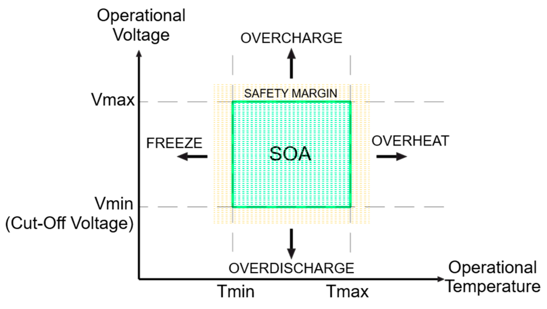
Figure 1. SOA of a lithium-ion battery.
The C-Rate
The BMS must monitor the current during the operation of the battery pack, as each cell has a maximum current level determined by the surrounding temperature, the temperature passing through the cells, and safety considerations. This charge and discharge current is often expressed by the C-Rate, reflecting the speed of charge and discharge relative to the capacity of a battery (in Amperes divided by Amperes per hour). Though extensive data exist on battery life expectancy concerning technology and charging profiles, many BMS manufacturers use proprietary charging tables. These may adjust the C-Rate based on certain factors, such as the battery’s SoC or age, which are often aligned with the manufacturer’s specific recommendations.
Protection
The BMS monitors parameters like the current, voltage, and temperature to detect and predict potential risks during the battery’s operation. This detection process involves considering both the current state of the battery (nowcasting) and predicting its future state (forecasting). These measurements guide secondary functions, such as cell balancing, current control, and cell isolation. The BMS ensures safety through three levels of actions:
-
First level: The BMS maintains cells within the SOA through cell balancing and temperature and voltage monitoring, and it may prompt active cooling action if available (BTMS takes action).
-
Second level: Power absorption during charging or drawing during discharging is limited to keep the battery within safe parameters.
-
Third level: The BMS halts operation if the temperature or voltage exceeds safe limits, thereby avoiding potential damage or hazards.
2.1.2. Management and Diagnosing
The BMS aims to extend battery life through a combination of diagnosis and management functions.
The diagnosis function involves forecasting the conditions of the cells that form the battery packs, with parameters like SoH and SoC playing a crucial role.
The management function calculates the current energy level stored in the battery, the power available to be drawn from the battery by the load at a given time, the estimated time for a full charge or discharge, and several other parameters required by the EMS to oversee the entire system. This function is closely intertwined with the diagnosis function and is overruled by security functions. Its main role is to regulate the charging and discharging processes of the batteries to extend their life expectancy by using various methods, such as cell balancing, current limiting, and disconnecting at specific charging conditions, like the cut-off voltage.
The operation of the management function depends on parameters like the battery technology, the SoH, and the application. Manufacturers may adjust the charging or discharging profiles based on certain factors, such as the required charge or discharge time, ambient conditions, the number of charge and discharge cycles the battery has experienced, response times of the application, and more. This could result in several charging and discharging profiles being used throughout the battery’s life or being actively adjusted based on measured conditions.
Lastly, the management function might also adopt approaches beyond optimizing battery life, such as economic considerations, availability, or grid support, thereby affecting decisions related to the battery’s operation.
2.1.3. Communication
The BMS is designed to communicate with the EMS and, optionally, with the BTMS. In certain topologies, the BMS may directly communicate with other BMSs and electronic devices, like smart chargers. If not, the connection is through the EMS.
The BMS uses a communication protocol consisting mainly of standardized solutions, such as CAN, Modbus, and serial communications, like RS-232 or RS-485. While wired solutions are typically used for reliability, wireless options, like Bluetooth, Zigbee, Wi-Fi, and cloud-based IOT communication, may also be available but are generally secondary [14][15].
In the event of a battery malfunction, the BMS will send a warning to the EMS and, optionally, other devices. Commonly, these warnings are given under two thresholds:
- -
-
Warning: The operation conditions are outside or near the normal working parameters without exceeding the safety conditions. A warning may not prompt drastic actions from the BMS, and it may wait for feedback from the EMS.
- -
-
Alert: The operation conditions are approaching the safety threshold limit, and the BMS will take appropriate action to ensure safety by terminating the battery operation or drastically reducing its output.
2.2. BMS Architecture and Topologies
When defining the ESS, a factor that takes importance is the way the BMS will interact with the energy storage. Though researchers are focusing on a complete BMS incorporating the global functions, the battery packs may incorporate one or several BMS circuits to allow for protection of the cells and security. Some examples are described below:
- -
-
Charger: Controls individual charging of a battery cell or a stack of cells in series, focusing on the charging voltage and the cell(s) temperature (e.g., [16]).
- -
-
Protector: Protects a single cell or a stack of cells in series from overcharge or overdischarge (e.g., [17]).
- -
-
Regulator: Balances the cells during charging and protects them against overdischarge (e.g., [18]).
- -
-
Balancer: Incorporates monitoring and balancing functions and normally applies to several cells from the pack (e.g., [19]).
- -
-
BMS: The ESS can incorporate several BMSs depending on distributed BMS topologies, where the BMSs will communicate with each other. Battery packs can be modular and may include just the protection system or the complete BMS with slave mode capabilities (e.g., [20]).
The connection to the BMS may follow several topologies and fall into two main categories:
- -
-
Centralized Architecture: This involves a single BMS with a control unit that manages all the cells in one or several battery packs through multiple communication channels. It is typically cheaper but limits the distance between battery packs and the BMS, which is possibly unsuitable for large-scale applications. An issue in a pack may affect the whole system, rendering the whole ESS inoperative.
- -
-
Distributed Architecture: Several BMSs or charge controller systems may be used while one main BMS will control the global operation. This architecture has two typical schemes:
- ○
-
Master–Slave: Each battery pack has a BMS with limited functions (slave BMS or S-BMS), while a master or M-BMS will control the whole operation and determine the charging strategies. Costlier and more robust than centralized options, this design fits better with larger systems and offers a shorter response time. The main vulnerability is that a failure in the main ESS will affect the whole pack, though the S-BMS may be able to retain partial functionality.
- ○
-
Modular: Uses several BMSs through the ESS, with one chosen as a master controlling the whole operation. This system is the sturdiest, because a failure on the main master can be fixed by promoting one of the slaves as the master, though it is the costliest.
It is also important to highlight that these topologies may also exist inside a singular battery pack at a smaller level (intra-battery communications [21]) and that combinations of these topologies into hybrid configurations are also possible [22][23].
2.3. BMS and Battery Charging
2.3.1. Battery Packs and Cells
When talking about the BMS, one important point to take into account is the battery pack topology, which is commonly named as a battery and composed of cells. A cell is the basic electrochemical unit used to generate or store electrical energy from stored chemical energy. A battery is an association of cells related to its final use; for example, in small electronics, a battery may consist of one cell, while in bigger applications, it consists of an association of two or more cells connected to each other either in series, in parallel, or in a combination of both. When a battery consists of two or more cells, it can also be called a battery pack. The battery pack arrangement follows several criteria that will be explained in further detail in following sections; the main criteria are the needed voltage, current and capacity required for the specific application.
2.3.2. The Life Cycle of a Battery
Manufacturers normally rate batteries for a number of cycles of charge and discharge until the end of its life (EOL). This metric is calculated by a drop of capacity, and a common value is 20% reduction (80% of the rated capacity), though this will differ depending on the end application [24][25][26][27]. A battery that is determined to be at its EOL for certain applications can be repurposed for less demanding applications, becoming “second life batteries”.
The number of cycles is calculated under ideal conditions, determined at a nominal voltage, ambient temperature, and maximum drawn current. However, research has identified various parameters that can influence battery life expectancy. Even though most of these parameters are mentioned in their respective sections, they have been grouped under this section for clarity:
- -
-
Operating outside of the SOA and protections: This can have a detrimental effect on battery durability. Monitoring different parameters, such as temperatures and voltages, allows for protections to be triggered to safeguard the battery. The safety and reliability functions of the BMS address these aspects and prevent situations that might degrade the battery.
- -
-
Charging and discharging profile of a battery: This can impact battery life expectancy, especially if a fast charge is maintained when the battery is almost fully charged. Charging and discharging are controlled by the management functionality of the BMS. It is vital to consider that lifespan maximization may not always be the BMS optimization goal, with economics or other variables factored into the decision-making process.
- -
-
Correct cell balancing: Proper balancing is crucial for achieving a sufficiently long life expectancy for the battery pack. The management functionality of the BMS should oversee cell balancing, equalizing the charge between cells, and preventing premature aging.
2.3.3. The Depth of Discharge
The Depth of Discharge (DoD) is a measure of the energy drawn from the battery, calculated as the discharged current from a fully charged battery divided by its nominal capacity, and expressed as a percentage of the battery’s overall capacity. The DoD is relevant in two key aspects:
1. DoD over time: A large current drawn from the battery in a small period of time can accelerate its aging. The DoD in relation to the time of discharge is a factor to take into account by the BMS to calculate the aging of a battery. When used this way, the parameter is normally measured as Ah.
2. Maximum DoD: Depending on the battery technology, it may be advisable to keep the SoC over a certain percentage to increase the battery life. In a battery, the DoD is the complement of the SoC, and their sum equals the total rated capacity of the battery. As the battery ages and its maximum SoC declines, the maximum achievable DoD must be adjusted.
2.3.4. Cut-off Voltage, Self-Discharge, and Maximum Voltage
The cut-off voltage, the point at which a battery discharge is terminated, is a manufacturer-prescribed value dependent on the battery technology. The BMS controls this critical parameter. Operating below the recommended voltage threshold can damage the battery, decrease its lifespan, and boost its rate of discharge. The cut-off voltage set up by the BMS will be higher than the undervoltage limit indicated by the cell manufacturer by a security margin to ensure that the battery does not reach a deep discharge stage.
The self-discharge of a battery is the recoverable capacity loss when no current is drawn by a load, and it varies with the technology and environment. Lead–acid batteries have a rapid self-discharge rate and require voltage maintenance to preserve capacity, while others, like lithium-ion, have a much slower rate. Self-discharge is often measured as a percentage of the rated capacity lost monthly at a certain temperature. The self-discharged energy, contrary to capacity loss through aging or other factors, is recoverable during the next charge cycle, provided that the battery does not reach a deep discharge stage; this is another factor to be supervised by the BMS.
Lastly, the maximum voltage of a battery, determined by its technology and defined by manufacturers, is a crucial factor to be considered by the BMS. A cell increases its resistance to the passing of current when the voltage is near a maximum point, at which point the absorbed current goes down to low C-rates. Exceeding the maximum voltage increases the temperature of the cell, promoting its degradation and aging, with adverse effects, like thermal rundown in lead–acid technologies and lithium plating on Li-ion batteries. Aged Li-ion batteries may experience plating below the maximum rated voltage, which brings the complex task to the BMS of adjusting the charging profile to compensate for the aging of a battery [28].
2.3.5. Battery Pack Topologies
The battery pack topology refers to the arrangement of the battery cells, which is crucial for delivering the required energy to a given load or application. This topology not only determines the energy in terms of voltage and current but also greatly influences how a BMS handles cell balancing. In stationary applications, a PCS can optimize the conversion of voltage from DC to AC, among other functions. The efficiency of the PCS depends on selecting an appropriate voltage for the battery pack topology. This optimization, in turn, determines the required current that the battery pack needs to deliver to the load [29].
Thus, the following aspects must be determined:
-
Maximum power the battery pack needs to deliver to the load.
-
Ideal voltage to supply to the PCS.
-
Maximum current the load will draw from the battery.
-
Total capacity needed for the battery pack.
-
Optimal topology to fulfill the requirements, extend the battery life, reduce costs, and minimize complexity. This can be achieved through various combinations of two basic topologies, series or parallel, or their hybridizations, Series Connected Configuration (SCC, Figure 2a) or Parallel Connected Configuration (PCC, Figure 2b).
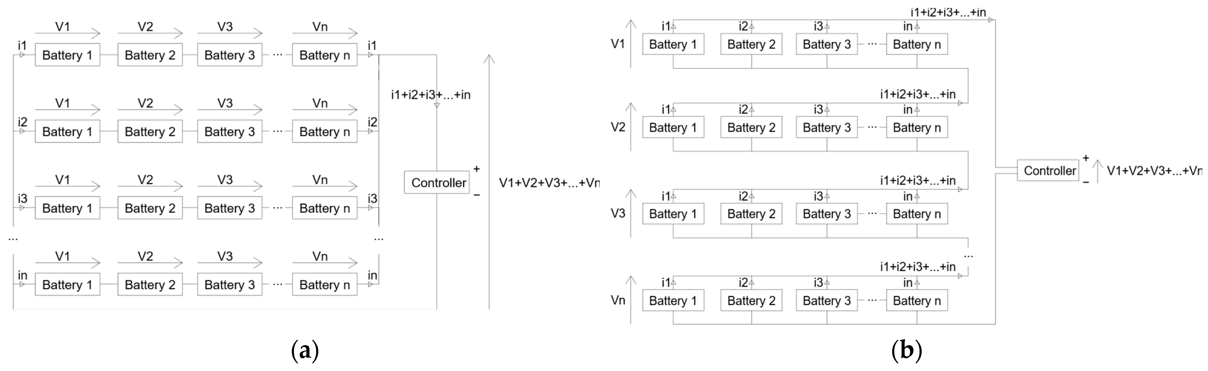
Figure 2. Hybrid topologies. (a) Stacks of cells connected in a Series Connected Configuration (SCC). (b) Stack of cells connected in a Parallel Connected Configuration (PCC).
2.3.6. Cell Balancing
During the production of batteries, small variations in cell resistance, maximum voltage, and capacity can exist, even if the battery pack assembly manufacturers select cells from the same model with similar capacities. These differences grow over time due to factors like the charging speed, current levels, temperature variations, and environmental conditions, leading to disparities between the cells in the SoC, capacities, aging rates, and self-discharge rates.
Cell balancing is a critical process managed by the BMS aiming to equalize the charge between cells. An appropriate balancing technique will allow the pack to absorb more energy and deliver more instantaneous power, and it becomes more crucial as the pack ages and the differences between the cells increase.
As explained in the previous section, the series connection of cells is more prone to this issue because the parallel connection will naturally equalize the cells. However, inconsistencies between the cells of a parallel connection will still lead to a faster performance decay rate, though, granted, at a lesser level compared to a series connection, making cell balancing still necessary for parallel and hybrid topologies, especially with aged cells [30].
Cell balancing techniques can be classified into two groups: dissipative equalization techniques and non-dissipative equalization techniques.
Dissipative Equalization
Dissipative equalization techniques, known as the Cell Bypass Method (CBM) or Cell To Heat (CTH) method, dissipate extra energy from a cell using parallel elements. These techniques should be used when charging because they do not allow reverse switching, which will result in a higher imbalance during discharge [31].
- -
-
Passive cell balancing: This method uses resistors in order to dissipate energy from the cell without active control. The main passive technique is the fixed shunt resistor method, where a fixed resistor of a calculated value is connected in parallel to allow the flow of current when a cell reaches full voltage. Other passive balancing techniques involve transistors, diodes, and variable resistors without an active control for more accurate balancing [32].
- -
-
Active cell balancing: This approach incorporates controlled switches to actively manage energy dissipation during charging. It adds complexity due to the need for control electronics, like microcontrollers, and the need to use inputs, like the voltage, temperature, or current passing through the cells. Cost and complexity can vary, and the control scheme may be adjusted throughout the battery’s life cycle. The simplest and most common method is the switchable shunt resistor method, which entails employing control switches with the resistors in series to manage current flow on demand through each cell. Another method described in the literature is the shunt transistor method [33][34].
Non-Dissipative Equalization
These methods redistribute the energy passing through the cells to equalize the charge. These systems may include, in addition to switches, capacitors, inductors, or transformers.
- -
-
Cell to Cell (CTC or C2C): Transfers excess energy from one cell to another using switches, capacitors, inductors, transformers (also called converters), or a combination of these. This type of balancing is divided into Adjacent Cell Balancing (ACB) and Direct Cell Balancing (DCB). In the ACB subtype, the energy flows to a cell adjacent (neighbor) to the one that is in a full state through the use of capacitors (single capacitor, switch capacitors, double-tiered switch capacitors), inductors (single inductor, multiple inductor), [31] or transformers (Ćuk converter, PWM controlled converter, quasi-resonant/resonant converter, multiple transformers) [35]. In the DCB subtype, a series of switches are introduced to control the transfer of energy between the cells and an equalizer, which may be a capacitor (flying capacitor method) [36], inductor (flying inductor method), [37] or transformer (multiphase interleaved converter) [38]. The use of switches allows for the transfer between any pair of cells on the stack or pack. In the more complex topologies, this method reaches an accurate SoC equalization between the cells, having also a good scalability and fast balancing process. The issue with this method is that an accurate control of the balancing requires the use of a big number of switches, which adds complexity to the system and cost to the BMS.
- -
-
Cell-to-Pack Methods (CTP or C2P): Transfer energy from a higher SoC cell to the entire pack continuously and dynamically via the use of capacitors, inductors, transformers, and a monitoring circuit. CTP methods are specific to the series topology of packs, and they have their best efficiency when only one cell of the series is unbalanced with an overcharge while the rest of cells are balanced. Conversely, their worst efficiency is reached when the unbalanced cell has a lower voltage than the rest of the series. Some CTP methods are the shunt inductor method [39], the boost shunting method, the multiple transformers method [39], the switched transformer method, the multisecondary windings transformer method [40], and the time-shared flyback converter method [41]. CTP methods suffer from high switching losses and slow balancing. Though they can make use of simpler balancing structures, an accurate SoC and voltage measurement from the batteries will need to include a certain level of complexity.
- -
-
Pack-to-Cell Methods (PTC or P2C): The energy is transferred from the whole pack to the cell with the lowest SoC in the pack, until the voltage is equalized. This type of circuit is the most adaptable for bidirectional balancing and it has slightly more efficiency than the CTP methods due to less energy losses during switching, although it has similar balancing speed. Some PTC methods are the voltage multiplier method, the full-bridge converter [42], the multiple transformers method [43], the switched transformer method [43], and the multisecondary windings transformer method [43][44].
- -
-
Cell-to-Pack-to-Cell Methods (CTPTC or C2P2C): These are higher in complexity as they operate in several directions, from the higher charged cell to the pack (CTP), from the pack to the lower charged cell (PTC), or from Pack to Pack (PTP) when the energy is transferred between stacks in the same pack. The level of complexity adds up to the BMS cost, but it is linked to higher conversion speed and energy efficiency. Some CTPTC methods include the bidirectional multiple transformers, the bidirectional switched transformer, and the bidirectional multisecondary windings transformer [45].
2.3.7. Reconfigurable BMS
Traditionally, battery packs are organized statically, and BMS devices that make use of cells in these arrangements have been defined as a “Static BMS” by a small number of authors [46][47][48][49]. In contrast, several types of reconfigurable architectures for the battery packs have been proposed, aiming at a major level of adaptability, rapid response to different type of applications, greater reliability and safety of use, and better cell equalization and cell life cycle. Because the reconfiguration of the pack is controlled by the BMS, these types of BMSs have been called a Reconfigurable BMS or R-BMS.
An R-BMS is capable of things like switching the configuration of the BMS between a series or parallel topology either globally or by stacks, isolating cells in case of fault or during equalization, regrouping cells according to aging parameters in different stacks, or adapting the configuration that best fits different services or types of loads. These systems incorporate a high number of switches and monitor circuitry, which can add to the BMS cost, and, in some cases, they will incorporate advanced algorithms that may need high computing power. Thus, several topologies have been proposed with different focuses, like increased performance of the system, high switching speed, less hardware complexity, or less computing requirements. Though this topic is an ongoing source of study, some topologies have recently been proposed, with several of these reviewed and evaluated in reference [46].
2.3.8. Battery Charging Profiles
A cell is considered discharged when its voltage falls below its cut-off voltage or when its SoC level falls below a value that is considered secure for its chemistry. At this point, the BMS will stop the discharge and get the battery ready to start the charging process. During charging, the BMS adjusts the supply of electrical energy controlling the current, voltage, and temperature until the battery voltage reaches a certain level or the current falls below the cut-off current. The charging profile, influenced by cell characteristics, may be calibrated by the BMS to adapt to the battery aging or differences between the cells within the battery pack.
Commonly, these schemes can be grouped under four major techniques:
- -
-
Constant current charging (CC): Supplies a constant current until maximum voltage. This method is mainly used when charging NiCd, NiMH, and Li-ion batteries. Finding a satisfactory charging current value is challenging, as there is a compromise between the charging speed and temperature control (aging). A variation of the CC method is the “Pulse Charging” method (Figure 3a), where the current is supplied in pulses through the charging process [50].
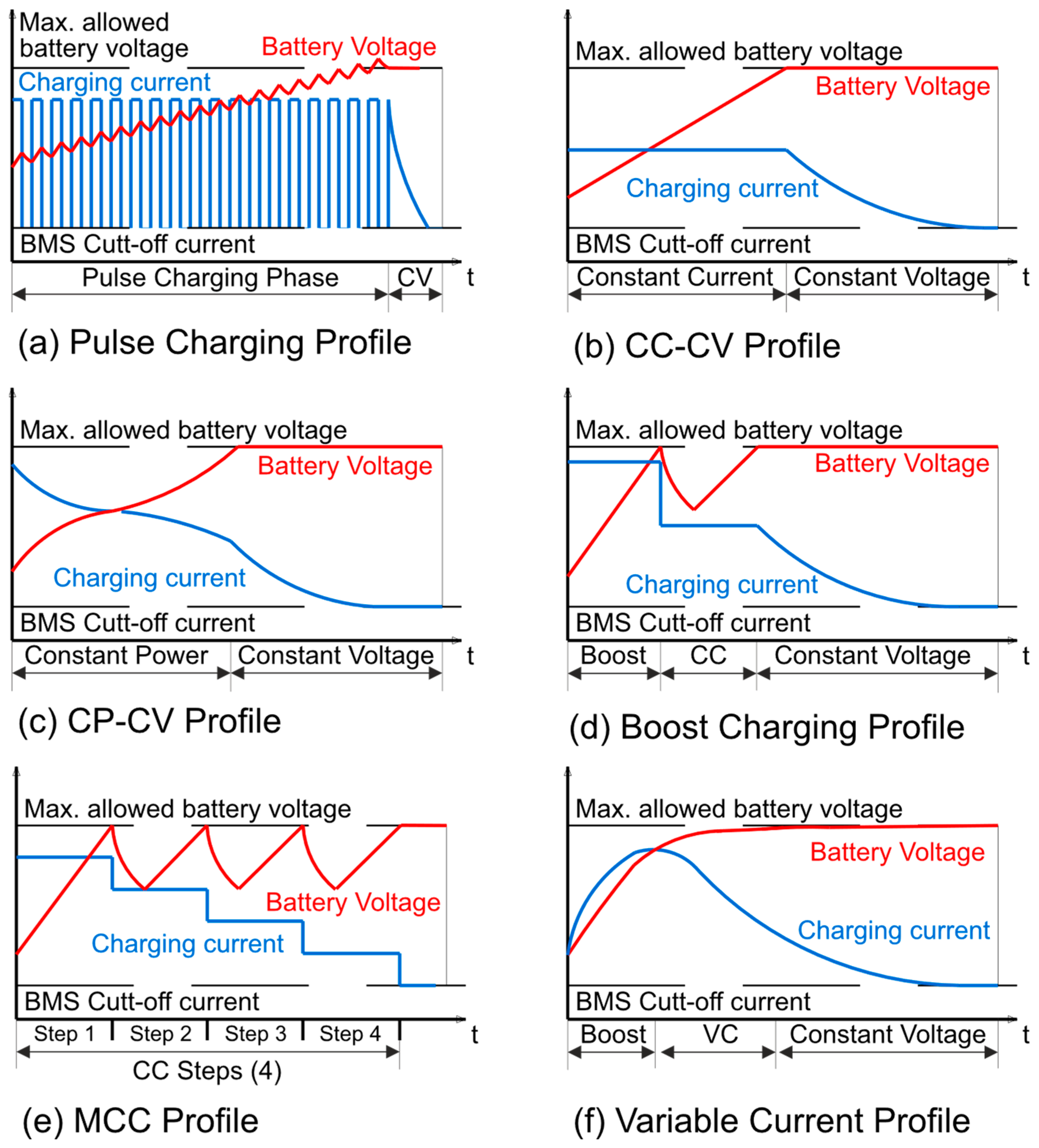 Figure 3. Representation of different types of charging profiles. (Red: Battery Voltage. Blue: Charging Current).
 - -
-
Constant-Voltage charging (CV): This second method regulates the voltage supplied in parallel to a cell or a series of cells, making it constant through the charging process. It protects the battery from overvoltage, because it cannot supply higher voltage than the cell maximum voltage, and the charging current decreases gradually while the battery charges. A high current is necessary at the early stages of the charging process [51]. The main challenge for CV charging is selecting a proper voltage value that balances the charging speed and aging of the battery. By selecting a voltage that enables high currents between 15% and 80% of the SoC’s range, fast charging is possible [52][53], though it may accelerate the aging of the cells.
- -
-
Constant-Current–Constant-Voltage charging (CC-CV): It combines the previous techniques, using CC in the early stages (bulk or bulking phase) until a safe threshold voltage is reached, and shifts to the CV method to complete the charging (absorption phase), as shown in Figure 3b. The charging time is mainly influenced by the calibration of the current used in the CC step, while the final SoC capacity is defined by the voltage selection during the CV step. This method is the most used for charging Li-ion and lead–acid cells. Variations include Constant-Power–Constant-Voltage (CP-CV) [54], shown in Figure 3c, and the Boost Charging [55], shown in Figure 3d. In the CP-CV method, the current and voltage are modified in such a way that constant power is supplied through the CC phase. In the Boost Charging method, the CC phase has two steps: first, large current value to elevate the voltage of the battery rapidly, and, second, a lower CC phase.
- -
-
Multi-stage Constant-Current charging (MCC): The MCC method [56] is mainly used in fast charging by using different constant current values for different stages of the SoC of the battery (Figure 3e). This method is calibrated to use high currents at the beginning of the charge, which decrease as long as the SoC value increases, controlling the current value that passes through the battery and making profiles optimized to balance the speed of charge and battery aging. This method is considered suitable to charge lead–acid, NiMH, and Li-ion batteries. While cells subjected to the MCC may have shorter life cycles than cells subjected to the CC-CV method, the life cycle can be extended by a proper calibration of the charging steps and the use of adaptive methods [57][58]. A variation of the MCC method is the Variable Current Charging [59], where instead of steps, the current is modified linearly through the charging (Figure 3f).
In batteries with high self-discharge rates, e.g., lead–acid batteries, after finalizing the charge, the BMS will try to maintain a certain voltage, called the Float Voltage [60][61][62]. This voltage is calculated considering the self-discharge rate of the battery. Technically, any battery can be float charged, but it is uncommon for batteries with low self-discharge rates, such as lithium-ion batteries, as it may reduce their lifetime. A common tactic for floating lithium batteries is to apply this method only to batteries that need to maintain their charge during long-term storage to ensure energy availability.
When the battery is subjected to long-term storage, it may be kept at a storage voltage. A common technique in these cases consists of using a lower float charge during the storage operation. Because this level is not sufficient to compensate for self-discharge, the BMS periodically adjusts the voltage to maintain the SoC value.
References
- European Commission. Communication from the Commission to the European Parliament, the European Council, the Council, the European Economic and Social Committee and the Committee of the Regions; The European Green Deal COM; European Commission: Brussels, Belgium, 2019; Volume 640.
- European Commission; Climate Action DG. Going Climate-Neutral by 2050: A Strategic Long-Term Vision for a Prosperous, Modern, Competitive and Climate-Neutral EU Economy; Publications Office of the European Union: Luxembourg, 2019.
- European Commission. Communication from the Commission to the European Parliament, the European Council, the Council, the European Economic and Social Committee and the Committee of the Regions; REPowerEU Plan COM; European Commission: Brussels, Belgium, 2022; Volume 230.
- European Commission. Commission Staff Working Document Implementing the Repower EU Action Plan: Investment Needs, Hydrogen Accelerator and Achieving the Bio-Methane Targets; SWD(2022) 230; European Commission: Brussels, Belgium, 2022.
- European Commission. Commission Recommendation of 14 March 2023 on Energy Storage—Underpinning a Decarbonised and Secure EU Energy System; European Commission: Brussels, Belgium, 2023.
- IEA. Grid-Scale Storage; IEA: Paris, France, 2022.
- European Commission; Directorate-General for Energy; Andrey, C.; Barberi, P.; Nuffel, L.; Gérard, F.; Gorenstein Dedecca, J.; Rademaekers, K.; El Idrissi, Y.; Crenes, M.; et al. Study on Energy Storage: Contribution to the Security of the Electricity Supply in Europe; Publications Office of the European Union: Luxembourg, 2020.
- Mordor Intelligence. Next Generation Advanced Battery Market Size & Share Analysis—Growth Trends & Forecasts (2023–2028); Mordor Intelligence: Hyderabad, India, 2023.
- IEA. Global EV Outlook 2023. Catching up with Climate Ambitions; IEA: Paris, France, 2023.
- Arshad, R. Battery Supply Chain: China Leads but What about Other Countries? Power Technol. Res. Inc.: Sunnyvale, CA, USA, 2021.
- Mardell, J. China Is Securing Battery Metals on the Global Stage; MERICS: Berlin, Germany, 2021.
- Cooper, C.; Zimmermann, A.; Aarup, S.A. China Leaves EU Playing Catchup in Race for Raw Materials; POLITICO Europe: Brussels, Belgium, 2023.
- Olabi, A.G.; Maghrabie, H.M.; Adhari, O.H.K.; Sayed, E.T.; Yousef, B.A.A.; Salameh, T.; Kamil, M.; Abdelkareem, M.A. Battery thermal management systems: Recent progress and challenges. Int. J. Thermofluids 2022, 15, 100171.
- Vogt, T. Wired vs. Wireless Communications in EV Battery Management. In Battery Management Systems; Texas Instruments: Dallas, TX, USA, 2020.
- Samanta, A.; Williamson, S.S. A Survey of Wireless Battery Management System: Topology, Emerging Trends, and Challenges. Electronics 2021, 10, 2193.
- NanJing Top Power ASIC Corp. TP4056 1A Standalone Linear Li-Lon Battery Charger with Thermal Regulation in SOP-8 Datasheet; NanJing Top Power ASIC Corp.: Nanjing, China, 2013.
- Fortune Semiconductor Corp. DW01A—One Cell Lithium-Ion/Polymer Battery Protection IC; Fortune Semiconductor Corp.: Taiwan, China, 2014.
- LDO Linear Regulator IC Datasheet for FS88XX Series and FS1XXX Series. Available online: http://www.ic-fortune.com/eng/new_product2_1.asp (accessed on 20 August 2023).
- Infineon Technologies. TLE9012DQU Li-Ion Battery Monitoring and Balancing IC Datasheet; Infineon Technologies: Neubiberg, Germany, 2022.
- Cegasa. eBick 280 Pro Technical Manual; Cegasa: Vitoria-Gasteiz, Spain, 2021.
- Pavic, I.; Beus, M.; Bobanac, V.; Pandzic, H. Decentralized Master-Slave Communication and Control Architecture of a Battery Swapping Station. In Proceedings of the 2018 IEEE International Conference on Environment and Electrical Engineering and 2018 IEEE Industrial and Commercial Power Systems Europe (EEEIC/I&CPS Europe), Palermo, Italy, 12–15 June 2018; pp. 1–6.
- Reindl, A.; Meier, H.; Niemetz, M. Scalable, Decentralized Battery Management System Based on Self-organizing Nodes. In Architecture of Computing Systems—ARCS 2020; Brinkmann, A., Karl, W., Lankes, S., Tomforde, S., Pionteck, T., Trinitis, C., Eds.; Lecture Notes in Computer Science; Springer International Publishing: Cham, Switzerland, 2020; Volume 12155, pp. 171–184. ISBN 978-3-030-52793-8.
- Kim, H.; Shin, K.G. DESA: Dependable, Efficient, Scalable Architecture for Management of Large-Scale Batteries. IEEE Trans. Ind. Inform. 2012, 8, 406–417.
- Ansari, S.; Ayob, A.; Hossain Lipu, M.S.; Hussain, A.; Saad, M.H.M. Remaining useful life prediction for lithium-ion battery storage system: A comprehensive review of methods, key factors, issues and future outlook. Energy Rep. 2022, 8, 12153–12185.
- Volan, T.; Vaz, C.R.; Uriona-Maldonado, M. Scenarios for end-of-life (EOL) electric vehicle batteries in China. Rev. Gest. 2021, 28, 335–357.
- Canals Casals, L.; Martinez-Laserna, E.; Amante García, B.; Nieto, N. Sustainability analysis of the electric vehicle use in Europe for CO2 emissions reduction. J. Clean. Prod. 2016, 127, 425–437.
- Ahmadi, L.; Yip, A.; Fowler, M.; Young, S.B.; Fraser, R.A. Environmental feasibility of re-use of electric vehicle batteries. Sustain. Energy Technol. Assess. 2014, 6, 64–74.
- Yang, X.-G.; Leng, Y.; Zhang, G.; Ge, S.; Wang, C.-Y. Modeling of lithium plating induced aging of lithium-ion batteries: Transition from linear to nonlinear aging. J. Power Sources 2017, 360, 28–40.
- Baumgartner, F.; Scholz, H.; Breu, A.; Roth, S. MPP voltage monitoring to optimise grid connected system design rules. In Proceedings of the 19th European Photovoltaic Solar Energy Conference, Paris, France, 7–11 June 2004.
- Wang, X.; Fang, Q.; Dai, H.; Chen, Q.; Wei, X. Investigation on Cell Performance and Inconsistency Evolution of Series and Parallel Lithium-Ion Battery Modules. Energy Technol. 2021, 9, 2100072.
- Hemavathi, S. Overview of cell balancing methods for Li-ion battery technology. Energy Storage 2021, 3, e203.
- Michael; Sujatmiko, R.P.; Abuzairi, T.; Rizkinia, M.; Kurniawan, T.A. Design of Overcharging Protection and Passive Balancing Circuits Using Dioda for Lithium-Ion Battery Management System. In Proceedings of the 2019 16th International Conference on Quality in Research (QIR): International Symposium on Electrical and Computer Engineering (IEEE), Padang, Indonesia, 22–24 July 2019; pp. 1–4.
- Stuart, T.A.; Zhu, W. Fast equalization for large lithium ion batteries. IEEE Aerosp. Electron. Syst. Mag. 2009, 24, 27–31.
- Zheng, Y.; Ouyang, M.; Lu, L.; Li, J.; Han, X.; Xu, L. On-line equalization for lithium-ion battery packs based on charging cell voltages: Part 1. Equalization based on remaining charging capacity estimation. J. Power Sources 2014, 247, 676–686.
- Shang, Y.; Zhang, C.; Cui, N.; Guerrero, J.M. A Cell-to-Cell Battery Equalizer with Zero-Current Switching and Zero-Voltage Gap Based on Quasi-Resonant LC Converter and Boost Converter. IEEE Trans. Power Electron. 2015, 30, 3731–3747.
- Shukla, A.; Ghosh, A.; Joshi, A. Capacitor Voltage Balancing Schemes in Flying Capacitor Multilevel Inverters. In Proceedings of the 2007 IEEE Power Electronics Specialists Conference (IEEE), Orlando, FL, USA, 17–21 June 2007; pp. 2367–2372.
- Hardy, C.; Ramadass, Y.; Scoones, K.; Le, H.-P. A Flying-Inductor Hybrid DC–DC Converter for 1-Cell and 2-Cell Smart-Cable Battery Chargers. IEEE J. Solid State Circuits 2019, 54, 3292–3305.
- Alajmi, B.N.; Marei, M.I.; Abdelsalam, I.; Ahmed, N.A. Multiphase Interleaved Converter Based on Cascaded Non-Inverting Buck-Boost Converter. IEEE Access 2022, 10, 42497–42506.
- Hwang, S.-S.; Baek, S.-W.; Kim, H.-W. Power Balance Method using Coupled Shunt Inductor and Multiple-Input Transformer for ISOP LLC Converter. Electronics 2019, 8, 352.
- Moghaddam, A.F.; Bossche, A.V.D. A Single Transformer for Active Cell Equalization Method of Lithium-Ion Batteries with Two Times Fewer Secondaries than Cells. Electronics 2019, 8, 951.
- Imtiaz, A.M.; Khan, F.H. “Time Shared Flyback Converter” Based Regenerative Cell Balancing Technique for Series Connected Li-Ion Battery Strings. IEEE Trans. Power Electron. 2013, 28, 5960–5975.
- Guo, Y.; Lu, R.; Wu, G.; Zhu, C. A high efficiency isolated bidirectional equalizer for Lithium-ion battery string. In Proceedings of the 2012 IEEE Vehicle Power and Propulsion Conference (IEEE), Seoul, Republic of Korea, 9–12 October 2012; pp. 962–966.
- Moore, S.W.; Schneider, P.J. A Review of Cell Equalization Methods for Lithium Ion and Lithium Polymer Battery Systems. In Proceedings of the SAE 2001 World Congress, Detroit, MI, USA, 5–8 March 2001.
- Bonfiglio, C.; Roessler, W. A cost optimized battery management system with active cell balancing for lithium ion battery stacks. In Proceedings of the 2009 IEEE Vehicle Power and Propulsion Conference (IEEE), Dearborn, MI, USA, 7–10 September 2009; pp. 304–309.
- Gallardo-Lozano, J.; Romero-Cadaval, E.; Milanes-Montero, M.I.; Guerrero-Martinez, M.A. Battery equalization active methods. J. Power Sources 2014, 246, 934–949.
- Viswanathan, V.; Palaniswamy, L.N.; Leelavinodhan, P.B. Optimization techniques of battery packs using re-configurability: A review. J. Energy Storage 2019, 23, 404–415.
- Steinhorst, S.; Shao, Z.; Chakraborty, S.; Kauer, M.; Li, S.; Lukasiewycz, M.; Narayanaswamy, S.; Rafique, M.U.; Wang, Q. Distributed reconfigurable Battery System Management Architectures. In Proceedings of the 2016 21st Asia and South Pacific Design Automation Conference (ASP-DAC), Macao, China, 25–28 January 2016; pp. 429–434.
- He, L.; Gu, L.; Kong, L.; Gu, Y.; Liu, C.; He, T. Exploring Adaptive Reconfiguration to Optimize Energy Efficiency in Large-Scale Battery Systems. In Proceedings of the 2013 IEEE 34th Real-Time Systems Symposium (IEEE), Vancouver, BC, Canada, 3–6 December 2013; pp. 118–127.
- Rahman, M.A.; De Craemer, K.; Buscher, J.; Driesen, J.; Coenen, P.; Mol, C. Comparative Analysis of Reconfiguration Assisted Management of Battery Storage Systems. In Proceedings of the IECON 2019—45th Annual Conference of the IEEE Industrial Electronics Society (IEEE), Lisbon, Portugal, 14–17 October 2019; pp. 5921–5926.
- Shen, W.; Vo, T.T.; Kapoor, A. Charging algorithms of lithium-ion batteries: An overview. In Proceedings of the 2012 7th IEEE Conference on Industrial Electronics and Applications (ICIEA), Singapore, 18–20 July 2012; pp. 1567–1572.
- Ku, K.; Son, S.-B.; Gim, J.; Park, J.; Liang, Y.; Stark, A.; Lee, E.; Libera, J. Understanding the constant-voltage fast-charging process using a high-rate Ni-rich cathode material for lithium-ion batteries. J. Mater. Chem. A 2022, 10, 288–295.
- Yourey, W.; Fu, Y.; Li, N.; Battaglia, V.; Tong, W. Design Considerations for Fast Charging Lithium Ion Cells for NMC/MCMB Electrode Pairs. Batteries 2021, 7, 4.
- Tomaszewska, A.; Chu, Z.; Feng, X.; O’Kane, S.; Liu, X.; Chen, J.; Ji, C.; Endler, E.; Li, R.; Liu, L.; et al. Lithium-ion battery fast charging: A review. eTransportation 2019, 1, 100011.
- Bajelvand, S.; Varjani, A.Y.; Babaki, A.; Vaez-Zadeh, S.; Jafari-Natanzi, A. Design of High-Efficiency WPT Battery Charging System with Constant Power and Voltage. In Proceedings of the 2022 13th Power Electronics, Drive Systems, and Technologies Conference (PEDSTC), Tehran, Iran, 1–3 February 2022; pp. 180–185.
- Notten, P.H.L.; Veld, J.H.G.O.H.; Beek, J.R.G.V. Boostcharging Li-ion batteries: A challenging new charging concept. J. Power Sources 2005, 145, 89–94.
- Khan, A.B.; Pham, V.-L.; Nguyen, T.-T.; Choi, W. Multistage constant-current charging method for Li-Ion batteries. In Proceedings of the 2016 IEEE Transportation Electrification Conference and Expo, Asia-Pacific (ITEC Asia-Pacific), Busan, Republic of Korea, 27–29 June 2016; pp. 381–385.
- Khan, A.B.; Choi, W. Optimal Charge Pattern for the High-Performance Multistage Constant Current Charge Method for the Li-Ion Batteries. IEEE Trans. Energy Convers. 2018, 33, 1132–1140.
- Jiang, L.; Li, Y.; Huang, Y.; Yu, J.; Qiao, X.; Wang, Y.; Huang, C.; Cao, Y. Optimization of multi-stage constant current charging pattern based on Taguchi method for Li-Ion battery. Appl. Energy 2020, 259, 114148.
- Cho, I.-H.; Lee, P.-Y.; Kim, J.-H. Analysis of the Effect of the Variable Charging Current Control Method on Cycle Life of Li-ion Batteries. Energies 2019, 12, 3023.
- Berndt, D.; Brautigam, R.; Teutsch, U. Temperature compensation of float voltage-the special situation of VRLA batteries. In Proceedings of the INTELEC 95: 17th International Telecommunications Energy Conference (IEEE), The Hague, The Netherlands, 29 October–1 November 1995; pp. 1–12.
- Harrison, A.I.; Bullough, R.P. Float voltage characteristics of valve regulated lead-acid batteries. In Proceedings of the 12th International Conference on Telecommunications Energy (IEEE), Orlando, FL, USA, 22–25 October 1990; pp. 213–218.
- Muneret, X.; Gobé, V.; Lemoine, C. Influence of float and charge voltage adjustment on the service life of AGM VRLA batteries depending on the conditions of use. J. Power Sources 2005, 144, 322–328.
More
Information
Subjects:
Engineering, Electrical & Electronic
Contributors
MDPI registered users' name will be linked to their SciProfiles pages. To register with us, please refer to https://encyclopedia.pub/register
:
View Times:
1.9K
Revisions:
2 times
(View History)
Update Date:
05 Sep 2023
Table of Contents


Notice
You are not a member of the advisory board for this topic. If you want to update advisory board member profile, please contact office@encyclopedia.pub.
OK
Confirm
Only members of the Encyclopedia advisory board for this topic are allowed to note entries. Would you like to become an advisory board member of the Encyclopedia?
Yes
No
${ textCharacter }/${ maxCharacter }
Submit
Cancel
Back
Comments
${ item }
|
${ item.createdUser.fullName }
${ item.createdAt }
${ item.vote }
${ item.reply }
Delete
${ reply.createdUser.fullName }
${ reply.createdAt }
${ reply.vote }
Delete
There is no reply to this comment~
${ item.replyTextCharacter }/${ item.replyMaxCharacter }
Submit
Cancel
More
No more~
There is no comment~
${ textCharacter }/${ maxCharacter }
Submit
Cancel
${ selectedItem.replyTextCharacter }/${ selectedItem.replyMaxCharacter }
Submit
Cancel
Confirm
Are you sure to Delete?
Yes
No