 +1 credit
Video Upload Options
Due to the high robustness and control flexibility of switched reluctance motors (SRMs), segmented structures have been widely studied to expand its applications in aerospace and other industrial fields.
1. Introduction
With the rapid development of power electronics and the gradual increase in the cost of permanent magnets (PMs), the switched reluctance motor (SRM) has been widely used in critical applications, such as starter/generators for aviation [1], driving systems for electric or hybrid vehicles [2][3][4], and household appliances [5], owing to its special and elaborated structure. Although SRM has lots of merits over induction motors (IM) and permanent magnet synchronous motors (PMSM), its shortcomings of noise, low power density, and radial vibration cannot be ignored. In an ideal SRM, the reluctance varies linearly with stator teeth overlap, generating a constant torque for a constant magnetic motive force (MMF). It is always designed to operate within the magnetic saturation zone of the ferromagnetic material to maximize torque density. However, in practical terms, saturation, magnetic field edge flux, and the rotor’s biconvex pole structure make the constant phase current produce torque and flux as a nonlinear function of rotor position. As a result, the generated torque may contain significant torque fluctuations, while torque ripple is believed to contribute significantly to another shortcoming of SRM, acoustic noise.
In the last few years, the research on the structure of SRMs has focused on segmental, bearingless, and linear types, from the traditional long flux path to the novelty short flux path, as shown in Figure 1. In some industrial applications that require high-speed rotation, conventional switched reluctance motors (CSRMs) typically adopt mechanical bearings to support the shaft of the motor system, causes severe wear on the mechanical bearing under long-term operation and leads to more heating problems. In severe cases, it will affect the uniformity of the air gap between the stator and rotor. It not only affects the efficiency of the motor, but also shortens the useful life of the machine and increases the maintenance burden of the motor and bearings. Moreover, the lubricant required for the mechanical bearings cannot be used in harsh environments such as vacuums and high temperatures. In order to solve the various problems posed by mechanical bearings in high-speed SRMs, air float, liquid float, and magnetic levitation bearings emerged in the community. Although these measures can achieve contactlessness and frictionlessness between shaft and rotor, air float and liquid float technologies must be equipped with special pneumatic and hydraulic systems. However, it will also make the motor larger. When the air pressure or hydraulic system fails, the air float and liquid float bearing will also fail. Consequently, the motor cannot run normally, thereby reducing the reliability of the motor system. The magnetic bearing technology fundamentally changed the traditional support form, with no contact between the shaft and rotor, high speed, high precision, long life, and other characteristics. On this basis, the seminal work of Higuchi proposed the concept of bearingless switched reluctance motors (BSRMs). However, it was not until the late 1990s that a more systematic study of BSRMs was conducted. For example, in [6], Takemoto exploited the similarity between the stator structure of SRMs and magnetic bearings by superimposing the levitation force winding of magnetic bearings on the stator windings of SRMs, such that the motor generates both levitation force and electromagnetic torque to achieve levitation and rotation of the motor rotor, thereby discarding the conventional bearing and reducing the weight of the SRM.
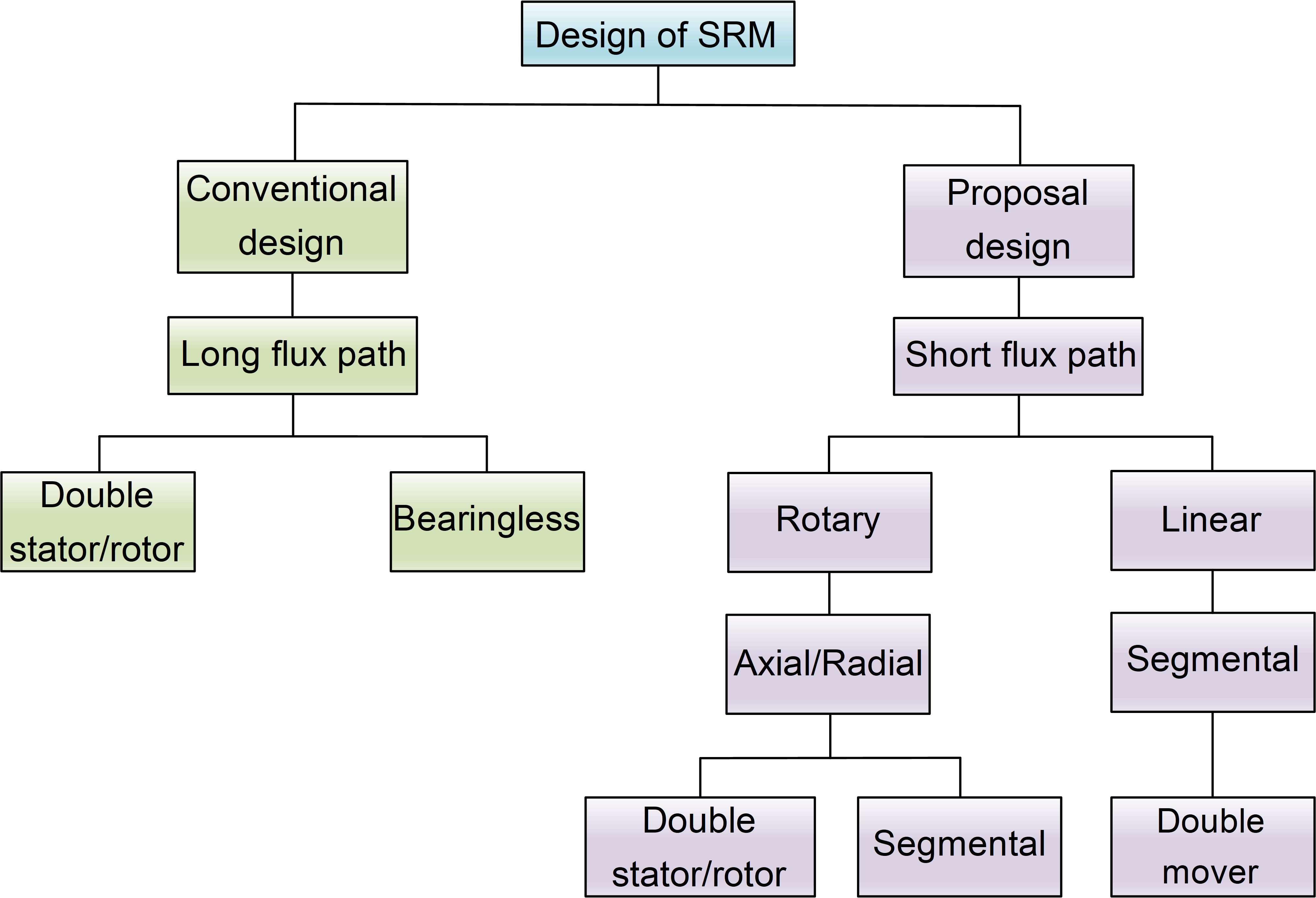
Figure 1. A classification of existing SRM topologies in recent years.
The segmental structure is a new topology based on the optimization of the flux path of the CSRM, of which the basic idea is to convert the stator or rotor from the previous conventional continuous iron core structure into discontinuous segments embedded in an isolator made of non-magnetic material to form a special short flux path which will reduce the coupling of adjacent phase fluxes and core losses. This idea was pioneered proposed by Lawerson, who divided the rotor of a synchronous reluctance motor (SynRM) into several discontinuous segments and replaced the magnetically conductive material in the center of the rotor with a non-magnetic material. It aims at increasing the magnetic utilization of SynRM by having more than half of the magnetic iron structure carry machine flux with short flux paths at any time during machine operation. Instead of the use of the conventional rotor teeth structure, it is constructed from a series of discrete segments. This method paved the way for the future research on the segmented switched reluctance motor (SSRM) [7].
2. Segmental Rotor Switched Reluctance Motor
Segmental rotor switched reluctance motors are designed to shorten the magnetic flux path (Figure 2), reduce iron loss, and increase motor torque by splitting the conventional convex rotor structure into several discontinuous rotor blocks and embedding them in a non-magnetic isolator made of magnetic isolation material. Common configurations are 6/5[8], 12/8[9], 12/10[10], 16/10[11] and axial flux 12/10[12],etc. According to the winding connection can be divided into whole pitch winding and centralized winding structure. It is worth noting that if a centralized winding connection is used, the stator usually adopts a hybrid stator pole structure. The wide teeth were defined as excitation poles and the narrow teeth were defined as auxiliary poles. All conductors in each stator slot are coupled only to their own MMF-driven flux. The mutual coupling between adjacent phases is small, increasing the electrical utilization and reducing the MMF requirements of the motor. The winding generated flux flows downward from the excitation pole, through the rotor segment, and returns from the adjacent auxiliary pole to either side of the excitation stator pole, with a short flux path.
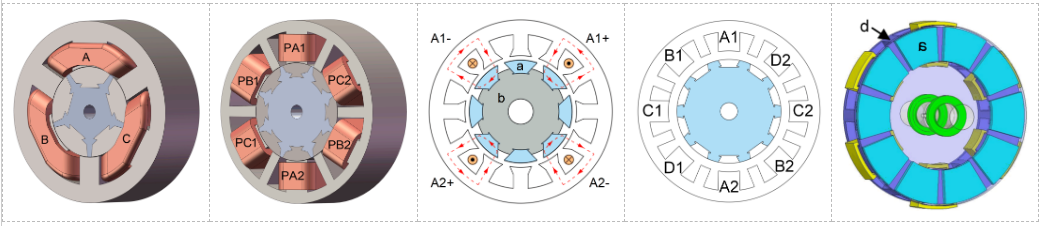
Figure 2. Common structures of segmental rotor switched reluctance motors
3. Segmental Stator Switched Reluctance Motor
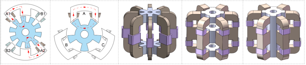
Analogously, the block stator switched reluctance motor divides the stator of the motor into multiple discontinuous stator blocks (Figure 3), forming an interference fit with the casing for fixation. Common types include C-type stator [13][14], E-type stator[15], and axial modular stator structures [16][17][18].
4. Double Stator Segmented Switched Reluctance Motor
5. Segmented Switched Reluctance Motor with Permanent Magnet assisted
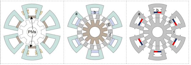
6. Segmental Rotor Linear Switched Reluctance Motor
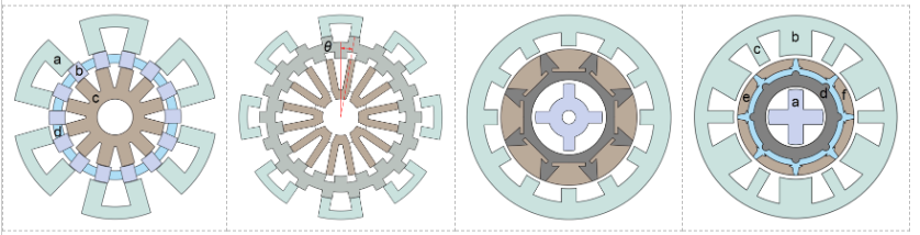
Linear switched reluctance motors (LSRM) are also an important branch of SRMs with structural variants similar to rotation SSRMs. The stator structure can still be divided into two structures according to windings' connections, i.e., equal-tooth and unequal-tooth forms. What is more, there are double mover structures with FPW and CW, and double mover segmented LSRM with toroidal windings [35][36][37], as shown in Figure 6.
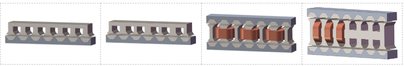
Figure 6. Common structures of segmental rotor LSRM.
7. Conclusion
References
- Virgilio Valdivia; Rebecca Todd; Frank J. Bryan; Andres Barrado; Antonio Lazaro; Andrew J. Forsyth; Behavioral Modeling of a Switched Reluctance Generator for Aircraft Power Systems. IEEE Trans. Ind. Electron. 2013, 61, 2690-2699.
- Fan Yi; Wen Cai; Modeling, Control and Seamless Transition of Bi-directional Battery-Driven Switched Reluctance Motor/Generator Drive based on Integrated Multiport Power Converter for Electric Vehicle Applications. IEEE Trans. Power Electron. 2015, 31, 1-1.
- Akira Chiba; Kyohei Kiyota; Nobukazu Hoshi; Masatsugu Takemoto; Satoshi Ogasawara; Development of a Rare-Earth-Free SR Motor With High Torque Density for Hybrid Vehicles. IEEE Trans. Energy Convers. 2014, 30, 175-182.
- Chun Gan; Jianhua Wu; Yihua Hu; Shiyou Yang; Wenping Cao; Josep M. Guerrero; New Integrated Multilevel Converter for Switched Reluctance Motor Drives in Plug-in Hybrid Electric Vehicles With Flexible Energy Conversion. IEEE Trans. Power Electron. 2016, 32, 3754-3766.
- Hao Chen; Jason J. Gu; Implementation of the Three-Phase Switched Reluctance Machine System for Motors and Generators. IEEE/ASME Trans. Mechatronics 2009, 15, 421-432.
- 6. Takemoto, M.; Shimada, K.; Chiba, A. A design and characteristics of switched reluctance type bearingless motors. In Pro-ceedings of the 4th International Symposium on Magnetic Suspension Technology, Gigu, Japan, 30 October–1 November 1997; pp. 49–63.
- P.J. Lawrenson; L.A. Agu; A new unexcited synchronous machine. null 1963, 110, 1275-1275.
- Zhenyao Xu; Jin-Woo Ahn. A novel 6/5 segmental rotor type switched reluctance motor: Concept, design and analysis; Institute of Electrical and Electronics Engineers (IEEE): Piscataway, NJ, United States, 2013; pp. 582-585.
- Zhenyao Xu; Jinguo Liu; Myeong-Ji Kim; Dong-Hee Lee; Jin-Woo Ahn; Characteristics Analysis and Comparison of Conventional and Segmental Rotor Type 12/8 Switched Reluctance Motors. IEEE Trans. Ind. Appl. 2018, 55, 3129-3137.
- B.C. Mecrow; J.W. Finch; E.A. El-Kharashi; A.G. Jack; Switched reluctance motors with segmental rotors. null 2002, 149, 245-254.
- Zhuicai Zhou; Xiaodong Sun; Long Chen; Zebin Yang; Shouyi Han; Ke Li; Jianguo Zhu; Youguang Guo. A segmented rotor type switched reluctance machine for BSGs of hybrid electric vehicles: Concept, design and analysis; Institute of Electrical and Electronics Engineers (IEEE): Piscataway, NJ, United States, 2017; pp. 1-4.
- Wang Bo; Dong-Hee Lee; Jin-Woo Ahn. A novel axial field SRM with segmental rotor: Concept, design and analysis; Institute of Electrical and Electronics Engineers (IEEE): Piscataway, NJ, United States, 2013; pp. 1-6.
- Marully Tanujaya; Dong-Hee Lee; Jin-Woo Ahn. Characteristic analysis of a novel 6/5 c-core type three-phase Switched Reluctance Motor; Institute of Electrical and Electronics Engineers (IEEE): Piscataway, NJ, United States, 2011; pp. 1-6.
- Pham Trung Hieu; Dong-Hee Lee; Jin-Woo Ahn. Design and control of a high speed segmental stator 4/3 switched reluctane motor; Institute of Electrical and Electronics Engineers (IEEE): Piscataway, NJ, United States, 2016; pp. 767-772.
- Cheewoo Lee; R. Krishnan; N. S. Lobo; Novel Two-Phase Switched Reluctance Machine Using Common-Pole E-Core Structure: Concept, Analysis, and Experimental Verification. IEEE Trans. Ind. Appl. 2009, 45, 703-711.
- Wen Ding; Yanfang Hu; Luming Wu; Analysis and Development of Novel Three-Phase Hybrid Magnetic Paths Switched Reluctance Motors Using Modular and Segmental Structures for EV Applications. IEEE/ASME Trans. Mechatronics 2015, 20, 2437-2451.
- Loránd Szabo; Mircea Ruba; Segmental Stator Switched Reluctance Machine for Safety-Critical Applications. IEEE Trans. Ind. Appl. 2012, 48, 2223-2229.
- Mircea Ruba; Ioan‐Adrian Viorel; Loránd Szabó; Modular stator switched reluctance motor for fault tolerant drive systems. IET Electr. Power Appl. 2013, 7, 159-169.
- Majid Asgar; Ebrahim Afjei; Hossein Torkaman; A New Strategy for Design and Analysis of a Double-Stator Switched Reluctance Motor: Electromagnetics, FEM, and Experiment. null 2015, 51, 1-8.
- Emine Bostanci; Lei Gu; Eva Cosoroaba; Mehdi Moallem; Babak Fahimi. Performance improvement and comparison of concentrated winding segmental rotor and double stator switched reluctance machines; Institute of Electrical and Electronics Engineers (IEEE): Piscataway, NJ, United States, 2016; pp. 1-1.
- Mohammadali Abbasian; Mehdi Moallem; Babak Fahimi; Double-Stator Switched Reluctance Machines (DSSRM): Fundamentals and Magnetic Force Analysis. IEEE Trans. Energy Convers. 2010, 25, 589-597.
- Arash Hassanpour Isfahani; Babak Fahimi; Comparison of Mechanical Vibration Between a Double-Stator Switched Reluctance Machine and a Conventional Switched Reluctance Machine. null 2014, 50, 293-296.
- E. Cosoroaba; W. Wang; B. Fahimi. Comparative study of two winding configurations for a double stator switched reluctance machine; Institute of Electrical and Electronics Engineers (IEEE): Piscataway, NJ, United States, 2014; pp. 1013-1017.
- Mohammad Amin Jalali Kondelaji; Mojtaba Mirsalim; Segmented-Rotor Modular Switched Reluctance Motor With High Torque and Low Torque Ripple. IEEE Trans. Transp. Electrification 2020, 6, 62-72.
- He Cheng; Shuo Liao; Wenju Yan; Development and Performance Analysis of Segmented-Double-Stator Switched Reluctance Machine. IEEE Trans. Ind. Electron. 2021, 69, 1298-1309.
- Wenju Yan; Hao Chen; Shuo Liao; Yongqiang Liu; He Cheng; Design of a Low-Ripple Double-Modular-Stator Switched Reluctance Machine for Electric Vehicle Applications. IEEE Trans. Transp. Electrification 2021, 7, 1349-1358.
- Qingguo Sun; Jianhua Wu; Chun Gan; Cenwei Shi; Jifeng Guo; DSSRM Design With Multiple Pole Arcs Optimization for High Torque and Low Torque Ripple Applications. IEEE Access 2018, 6, 27166-27175.
- Zhenyao Xu; Jialu Ding; Zhijun Fan; Huijun Wang; Fengge Zhang; Characteristics Analysis of a Novel 12/8 Double Stator Bearingless Switched Reluctance Motor. J. Electr. Eng. Technol. 2022, 18, 347-357.
- Zhenyao Xu; Zhuhua Zhou; Zhijun Fan; Yue Qi; Fengge Zhang. Characteristics Analysis and Comparison of Conventional and Segmental Rotor Type 12/8 Double Stator Bearingless Switched Reluctance Motors; Institute of Electrical and Electronics Engineers (IEEE): Piscataway, NJ, United States, 2022; pp. 1-5.
- Y. Hasegawa; K. Nakamura; O. Ichinokura. Basic consideration of switched reluctance motor with auxiliary windings and permanent magnets; Institute of Electrical and Electronics Engineers (IEEE): Piscataway, NJ, United States, 2012; pp. 92-97.
- Kenji Nakamura; Kohei Murota; Osamu Ichinokura. Characteristics of a novel switched reluctance motor having permanent magnets between the stator pole-tips; Institute of Electrical and Electronics Engineers (IEEE): Piscataway, NJ, United States, 2007; pp. 1-5.
- Hongsik Hwang; Sungwoo Bae; Cheewoo Lee; Analysis and Design of a Hybrid Rare-Earth-Free Permanent Magnet Reluctance Machine by Frozen Permeability Method. null 2016, 52, 1-4.
- S. Ullah; S.P. McDonald; R. Martin; G.J. Atkinson. A permanent magnet assisted switched reluctance machine for more electric aircraft; Institute of Electrical and Electronics Engineers (IEEE): Piscataway, NJ, United States, 2016; pp. 79-85.
- Mohammad Amin Jalali Kondelaji; Mojtaba Mirsalim. Double-stator PM-assisted modular variable reluctance motor for EV applications; Institute of Electrical and Electronics Engineers (IEEE): Piscataway, NJ, United States, 2018; pp. 236-240.
- Babak Ganji; Mohamad Hasan Askari. Different topologies for linear switched reluctance motor with segmental translator; Institute of Electrical and Electronics Engineers (IEEE): Piscataway, NJ, United States, 2016; pp. 874-878.
- Xiaojian Yi; Changqing Zhu; Can Huang; Daohan Wang; Xiuhe Wang. Design Optimization of Linear Switched Reluctance Motor with Segmental Mover; Institute of Electrical and Electronics Engineers (IEEE): Piscataway, NJ, United States, 2021; pp. 1-6.
- Daohan Wang; Xingfei Du; Dengxu Zhang; Xiuhe Wang; Design, Optimization, and Prototyping of Segmental-Type Linear Switched-Reluctance Motor With a Toroidally Wound Mover for Vertical Propulsion Application. IEEE Trans. Ind. Electron. 2017, 65, 1865-1874.

