Your browser does not fully support modern features. Please upgrade for a smoother experience.
Submitted Successfully!
 +1 credit
Thank you for your contribution! You can also upload a video entry or images related to this topic.
For video creation, please contact our Academic Video Service.
| Version | Summary | Created by | Modification | Content Size | Created at | Operation |
|---|---|---|---|---|---|---|
| 1 | Mahdi Yeganeh | -- | 1353 | 2023-08-31 14:11:36 | | | |
| 2 | Jason Zhu | Meta information modification | 1353 | 2023-09-01 07:37:48 | | |
Video Upload Options
We provide professional Academic Video Service to translate complex research into visually appealing presentations. Would you like to try it?
Cite
If you have any further questions, please contact Encyclopedia Editorial Office.
Yeganeh, M.; Shahryari, Z.; Talib Khanjar, A.; Hajizadeh, Z.; Shabani, F. Inclusions and Segregations in the Selective Laser-Melted Alloys. Encyclopedia. Available online: https://encyclopedia.pub/entry/48696 (accessed on 25 June 2026).
Yeganeh M, Shahryari Z, Talib Khanjar A, Hajizadeh Z, Shabani F. Inclusions and Segregations in the Selective Laser-Melted Alloys. Encyclopedia. Available at: https://encyclopedia.pub/entry/48696. Accessed June 25, 2026.
Yeganeh, Mahdi, Zahra Shahryari, Ali Talib Khanjar, Zeinab Hajizadeh, Fatemeh Shabani. "Inclusions and Segregations in the Selective Laser-Melted Alloys" Encyclopedia, https://encyclopedia.pub/entry/48696 (accessed June 25, 2026).
Yeganeh, M., Shahryari, Z., Talib Khanjar, A., Hajizadeh, Z., & Shabani, F. (2023, August 31). Inclusions and Segregations in the Selective Laser-Melted Alloys. In Encyclopedia. https://encyclopedia.pub/entry/48696
Yeganeh, Mahdi, et al. "Inclusions and Segregations in the Selective Laser-Melted Alloys." Encyclopedia. Web. 31 August, 2023.
Copy Citation
During the manufacturing process, various defects can occur in metals, which can negatively impact their mechanical properties and structural integrities. These defects include gas pores, lack of fusions, keyholes, melt pools, cracks, inclusions, and segregations.
selective laser melting (SLM)
laser powder bed fusion (LPBF)
inclusions
segregations
1. An Introduction to Additive Manufacturing
The method of leveraging 3D model data to produce complicated geometries and structures is known as additive manufacturing (AM). Another name for it is solid–freeform fabrication, rapid prototyping, and layer manufacturing. As compared to traditional subtractive manufacturing processes dependent on powder or wire feedstock heated or fused through a high temperature reservoir and created using an electronically controlled heat source mechanism, this method involves layer-by-layer production. The time between idea conception and new product creation can be shortened by adopting this technique. Early in the 1980s, Charles Hull was the one who first commercialized this technique. Currently, AM is utilized to make parts for rocket engines, artificial heart pumps, corneas, implants, bridges, jewelry, food products, vehicle parts, and residences. By adding material layer by layer using a 3D printer, the additive manufacturing process creates 3D elements from CAD data [1][2]. An overview of important facets of the AM approach was given in the roadmap Bourell et al. released in 2009, comprising [3]:
-
Modeling and management of processes;
-
Resources, procedures, and equipment;
-
Uses in biomedicine;
-
Uses for sustainability and energy.
According to recent research, additive manufacturing can significantly reduce the need for machine tools in traditional casting techniques, which has an effect on the production process [4]. A number of charming features make AM appealing, including lightweight design, automation, greater flexibility, no material waste, reduced cost, no need for skilled craftspeople due to an automated process, very little noise, and eco-friendliness. However, there are several disadvantages to adopting AM technology, such as the expensive machine, restrictions on object size, higher unemployment, sluggish construction pace, and more. However, contemporary R&D has reduced the price of 3D printing devices, making them more affordable and available in classrooms, labs, libraries, homes, etc. [1].
2. Classification of AM
According to the guidelines set by the ASTM-F42 committee, additive manufacturing (AM) can be classified into seven categories. One common classification system is based on these guidelines, which include vat photopolymerization (VP), material jetting (MJ), binder jetting (BJ), material extrusion (ME), sheet lamination (SL), powder bed fusion (PBF), and directed energy deposition (DED) [5]. Figure 1 shows different AM methods [6]. AM technology allows for the production of components using a wide range of materials, each with its unique properties and applications.
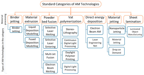
Figure 1. Different types of additive manufacturing [6].
3. Materials
Any production method, including AM processes, requires that the material be prepared in a manner that is appropriate with the technique (for example, powder, sheet, wire, or liquid). For instance, the feedstock for photopolymer jetting and vat polymerization must be a thermoplastic polymer or plastic monomer that can crosslink when subjected to external magnetic waves [7]. AM components can be manufactured from ceramics, polymers, metals, plastics, and their combinations. There is still room for improvement in the materials. Metals are widely used in AM due to their excellent mechanical and thermal properties. Additive manufacturing techniques such as powder bed fusion and directed energy deposition have been used to produce high-strength metal components such as aerospace parts, automotive components, and medical implants. Polymers are another popular material used in AM, mainly due to their low cost, light weight, and ease of processing. AM techniques such as fused deposition modeling and stereolithography have been used to produce polymer components with high accuracy and precision, making them suitable for prototyping and low-volume production. Ceramics are also commonly used in AM, particularly for applications that require high strength, wear resistance, and high-temperature stability. AM techniques such as powder bed fusion and stereolithography have been used to produce ceramic components such as biomedical implants, aerospace components, and electronic devices. Composites are a relatively new class of materials that have gained popularity in AM due to their unique combination of properties. Composites are made by combining two or more materials with different properties to create a material with improved strength, stiffness, and durability. AM techniques such as fused filament fabrication and binder jetting have been used to produce composite components such as automotive parts, aerospace components, and sporting equipment [1][4][5][8][9].
4. Laser Powder Bed Fusion (LPBF)/Selective Laser Melting (SLM)
In additive fabrication, the most common type is powder bed fusion. Thin films of powder are put to a prepared surface during powder bed fusion, and energy is delivered at specified locations on the model to fuse the powder [10]. A 3D part is created by applying successive layers of powder and then repeating the process until the part is complete. Powder bed fusion is alternatively designated selective laser melting (SLM), selective laser sintering (SLS), direct metal laser melting, and electron beam melting (EBM). A powder bed fusion machine melts instead of sinters parts with full densities [10][11].
In LPBF/SLM, several steps are involved, from preparing CAD data to withdrawing fabricated parts from the building plate. Before uploading CAD data to SLM machines for component manufacturing, STereoLithography (STL) files must be processed by software. This process enables laser scanning of individual layers and supports dangling features. Inside a building chamber, a small film of metal powder is applied to the substrate plate to begin the building process. Based on the collected data, the powder is applied, heated, and fused using a high-energy density laser. Following the laser scanning, a new powder layer is placed, and that layer is again examined. Every layer of powder must be added in order to construct the pieces, and then the process will continue. Modification of the parameters such as laser power, scanning speed, hatch spacing, and layer thickness can lead to the fusion a single melt vector completely with the surrounding melt vectors. A separate component can be manually or electrically discharged (EDM) separated from the substrate plate after laser scanning has been completed. All steps of the process are automated, except for preparing the data and removing fabricated components from the platform [11][12][13]. Figure 2 illustrates the concept of LPBF building [12].
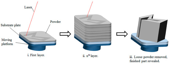
Figure 2. Scheme of LPBF process: (i) Laser melts specific areas of the powder bed (ii), Repeating the process for following layers, and (iii) Removing unattached powder and revealing the finished product “Reprinted with permission from Ref. [12] 2015. AIP Publishing”.
Often, an inert atmosphere is provided by nitrogen or argon gas in the building chamber for protection against oxidation during the LPBF process. In addition, some LPBF machines are able to pre-heat either the build chamber or the substrate plate. Between 20 to 100 µm is the typical thickness of the layer [12][14]. It has been demonstrated that LPBF can fully melt powder materials, producing near-net-shape parts without post-processing. An LPBF process is more efficient, faster, and reliable than binder-based laser sintering methods [10][11][12]. Nevertheless, this laser method can result in various defects in the final parts, which may affect the alloy’s performance. As a result, the strength and durability of the alloys may be compromised. This can lead to inferior performance and reduced reliability of the parts. Therefore, it is necessary to investigate and study the emerging defects in the SLM-manufactured alloys.
Microstructure of SLM Parts
In Figure 3, a schematic representation depicts the dependence of grain size and shape on solidification conditions. Increasing energy density leads to a reduction in temperature gradient. An equiaxed grain shape forms under a high solidification velocity and low temperature gradient, whereas a planar grain structure forms under high temperature gradient and low solidification velocity. A columnar grain shape is formed in the intermediate region (grey area in Figure 3). When transitioning to AM conditions, a cellular dislocation structure also forms due to a higher solidification velocity and larger temperature gradient. The SLM parameters fall within the columnar region, but adjustments to the parameters can result in an equiaxed grain structure for the isotropic material properties. Increasing both solidification velocity and temperature gradient brings the conditions closer to the SLM process, whereas decreasing the velocity and gradient leads to conditions similar to conventional casting [15].
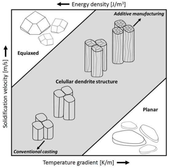
Figure 3. A schematic diagram illustrating the influence of solidification velocity and temperature gradient on the microstructure [15].
References
- Kumar, R.; Kumar, M.; Chohan, J.S. Material-specific properties and applications of additive manufacturing techniques: A comprehensive review. Bull. Mater. Sci. 2021, 44, 181.
- Blakey-Milner, B.; Gradl, P.; Snedden, G.; Brooks, M.; Pitot, J.; Lopez, E.; Leary, M.; Berto, F.; du Plessis, A. Metal additive manufacturing in aerospace: A review. Mater. Des. 2021, 209, 110008.
- Frazier, W.E. Metal additive manufacturing: A review. J. Mater. Eng. Perform. 2014, 23, 1917–1928.
- Jafferson, J.M.; Chatterjee, D. A review on polymeric materials in additive manufacturing. Mater. Today Proc. 2021, 46, 1349–1365.
- Srivastava, M.; Rathee, S.; Patel, V.; Kumar, A. A review of various materials for additive manufacturing: Recent trends and processing issues. J. Mater. Res. Technol. 2022, 21, 2612–2641.
- Akessa, A.D.; Lemu, H.G. Overview study on challenges of additive manufacturing for a healthcare application. IOP Conf. Ser. Mater. Sci. Eng. 2021, 1201, 012041.
- Bourell, D.; Kruth, J.P.; Leu, M.; Levy, G.; Rosen, D.; Beese, A.M.; Clare, A. Materials for additive manufacturing. CIRP Ann.-Manuf. Technol. 2017, 66, 659–681.
- Parandoush, P.; Lin, D. A review on additive manufacturing of polymer-fiber composites. Compos. Struct. 2017, 182, 36–53.
- Jahangir, N.; Arif, M.; Mamun, H.; Sealy, M.P. A review of additive manufacturing of magnesium alloys. AIP Conf. Proc. 2018, 1980, 030026.
- King, W.E.; Anderson, A.T.; Ferencz, R.M.; Hodge, N.E.; Kamath, C.; Khairallah, S.A.; Rubenchik, A.M. Laser powder bed fusion additive manufacturing of metals; physics, computational, and materials challenges. Appl. Phys. Rev. 2015, 2, 041304.
- Khairallah, S.A.; Anderson, A.T.; Rubenchik, A.; King, W.E. Laser powder-bed fusion additive manufacturing: Physics of complex melt flow and formation mechanisms of pores, spatter, and denudation zones. Acta Mater. 2016, 108, 36–45.
- Yap, C.Y.; Chua, C.K.; Dong, Z.L.; Liu, Z.H.; Zhang, D.Q.; Loh, L.E.; Sing, S.L. Review of selective laser melting: Materials and applications. Appl. Phys. Rev. 2015, 2, 041101.
- Wu, X.; Zhang, D.; Guo, Y.; Zhang, T.; Liu, Z. Microstructure and mechanical evolution behavior of LPBF (laser powder bed fusion)-fabricated TA15 alloy. J. Alloys Compd. 2021, 873, 159639.
- Huang, J.Y.; Chang, C.H.; Wang, W.C.; Chou, M.J.; Tseng, C.C.; Tu, P.W. Systematic evaluation of selective fusion additive manufacturing based on thermal energy source applied in processing of titanium alloy specimens for medical applications. Int. J. Adv. Manuf. Technol. 2020, 109, 2421–2429.
- Donik, C.; Kraner, J.; Paulin, I.; Godec, M. Influence of the Energy Density for Selective Laser Melting on the Microstructure and Mechanical Properties of Stainless Steel. Metals 2020, 10, 919.
More
Information
Subjects:
Metallurgy & Metallurgical Engineering
Contributors
MDPI registered users' name will be linked to their SciProfiles pages. To register with us, please refer to https://encyclopedia.pub/register
:
View Times:
572
Revisions:
2 times
(View History)
Update Date:
01 Sep 2023
Table of Contents


Notice
You are not a member of the advisory board for this topic. If you want to update advisory board member profile, please contact office@encyclopedia.pub.
OK
Confirm
Only members of the Encyclopedia advisory board for this topic are allowed to note entries. Would you like to become an advisory board member of the Encyclopedia?
Yes
No
${ textCharacter }/${ maxCharacter }
Submit
Cancel
Back
Comments
${ item }
|
${ item.createdUser.fullName }
${ item.createdAt }
${ item.vote }
${ item.reply }
Delete
${ reply.createdUser.fullName }
${ reply.createdAt }
${ reply.vote }
Delete
There is no reply to this comment~
${ item.replyTextCharacter }/${ item.replyMaxCharacter }
Submit
Cancel
More
No more~
There is no comment~
${ textCharacter }/${ maxCharacter }
Submit
Cancel
${ selectedItem.replyTextCharacter }/${ selectedItem.replyMaxCharacter }
Submit
Cancel
Confirm
Are you sure to Delete?
Yes
No