Your browser does not fully support modern features. Please upgrade for a smoother experience.
Submitted Successfully!
 +1 credit
Thank you for your contribution! You can also upload a video entry or images related to this topic.
For video creation, please contact our Academic Video Service.
| Version | Summary | Created by | Modification | Content Size | Created at | Operation |
|---|---|---|---|---|---|---|
| 1 | Xiaodong Zhang | -- | 2464 | 2023-08-14 04:45:02 | | | |
| 2 | Camila Xu | Meta information modification | 2464 | 2023-08-14 08:28:41 | | |
Video Upload Options
We provide professional Academic Video Service to translate complex research into visually appealing presentations. Would you like to try it?
Cite
If you have any further questions, please contact Encyclopedia Editorial Office.
Hu, X.; Li, Z.; Miao, L.; Fang, F.; Jiang, Z.; Zhang, X. Imaging Principle of the Light Field Camera. Encyclopedia. Available online: https://encyclopedia.pub/entry/48014 (accessed on 28 July 2026).
Hu X, Li Z, Miao L, Fang F, Jiang Z, Zhang X. Imaging Principle of the Light Field Camera. Encyclopedia. Available at: https://encyclopedia.pub/entry/48014. Accessed July 28, 2026.
Hu, Xiaoming, Zhuotong Li, Li Miao, Fengzhou Fang, Zhongjie Jiang, Xiaodong Zhang. "Imaging Principle of the Light Field Camera" Encyclopedia, https://encyclopedia.pub/entry/48014 (accessed July 28, 2026).
Hu, X., Li, Z., Miao, L., Fang, F., Jiang, Z., & Zhang, X. (2023, August 14). Imaging Principle of the Light Field Camera. In Encyclopedia. https://encyclopedia.pub/entry/48014
Hu, Xiaoming, et al. "Imaging Principle of the Light Field Camera." Encyclopedia. Web. 14 August, 2023.
Copy Citation
A light field camera has the benefit of being compact and reconstructing the 3D shape of the surface with just one shot. At the same time, it can provide dense multiple angles and obtain richer image information, improving measurement accuracy and solving measurement challenges such as occlusion.
light field camera
calibration technology
reconstruction algorithms
1. Introduction
Machine vision measurement is an effective industrial inspection technology that offers the benefits of fast speed, high accuracy, and low cost. It also has great development potential and a wide range of prospective applications. Machine vision measurement is currently employed extensively in the fields of aerospace, biomedicine, agricultural production, and social life [1][2][3][4]. For instance, in the aerospace industry, the positional estimate of cooperative targets is accomplished using visual measuring systems [5]. Light detection and ranging (LiDAR) is used to acquire the position of non-cooperative space targets with an accurate result [6]. However, the applications of each of the aforementioned measurement techniques have some drawbacks. Table 1 lists the advantages and disadvantages of them. Single camera systems, despite their compact size and light weight, have a limited ability to measure depth and must be supplemented by displacement motion mechanisms, which will increase the complexity of the measuring system and the measurement time [7]. Multi-view systems can measure 3D objects with a high degree of precision through multi-camera calibration and matching algorithms. However, each time the system is set up, the multi-view system must be re-calibrated and the relative position must be stable. Additionally, multi-view systems are expensive and bulky [8]. LiDAR systems offer great measurement precision, but they are expensive and heavy and their sampling rate low [8]. The requirements for measuring efficiency and measurement system size are challenging for such measurement systems to achieve. With continuous research on light field theory and light field acquisition methods, the concept of the light field camera has been proposed and applied to the measurement [9]. A light field camera has the benefit of being compact and reconstructing the 3D shape of the surface with just one shot. At the same time, it can provide dense multiple angles and obtain richer image information, improving measurement accuracy and solving measurement challenges such as occlusion. However, the light field cameras suffer from major measuring shortcomings as a result of their unusual design. The first is the trade-off that light field cameras make in terms of spatial resolution in order to be able to estimate depth, which in theory lowers the measurement accuracy and becomes the main issue impeding the development and application of the light field camera. At the same time, light field images often have very high resolution and require the use of complex image-processing techniques, which lead to problems such as memory usage and longer computational times.
Table 1. Comparison of the advantages and disadvantages of measurement systems.
| System | Advantages | Disadvantages |
|---|---|---|
| Single camera | Simple system, small size, and light weight | Poor depth recovery |
| Multi-view system | High measurement accuracy and retention of features such as color and texture | Cumbersome calibration and large system size |
| LiDAR | Long measuring distance, high measuring accuracy, and low influence by light | High cost and low sampling accuracy |
| Light field camera | Small size, light weight, good dynamic performance, and dense view | Low measurement accuracy and high data volume |
2. Imaging Principle of the Light Field Camera
2.1. The Structure of the Light Field Camera
The ability of light field cameras to achieve three-dimensional measurements from a single image is inextricably linked to their special structure. The structural changes to the light field camera are shown in Figure 1. Adelson et al. [10] was the first to conceptualize the light field camera, placing a tiny pinhole array on the image plane to analyze the structure of light at each of its macroscopic pixels. However, the small light flux of the pinhole arrays did not allow for good imaging. With the advancement of microlens array fabrication technology, Ng et al. [9] created the first standard light field camera, by swapping the prior pinhole array for a microlens array. Since then, researchers have begun to pay more and more attention to light field cameras and have started to use them for measurements.
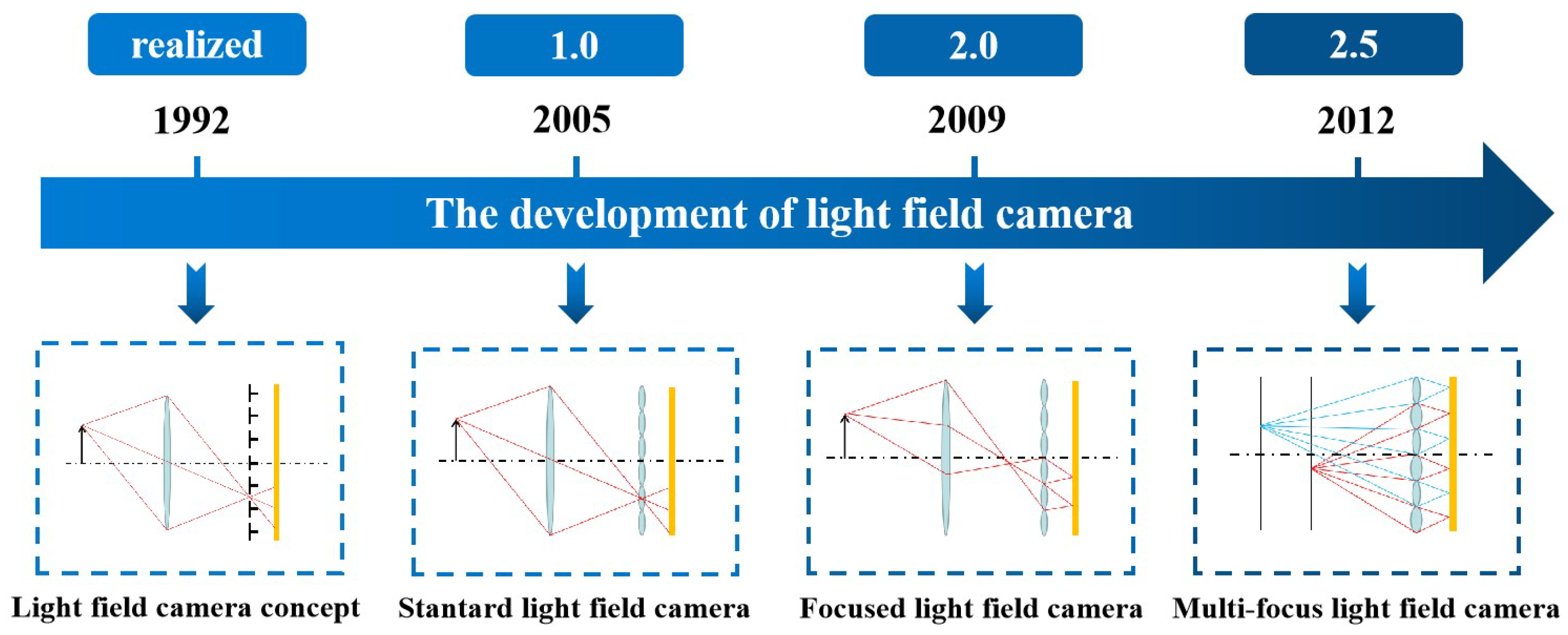
Figure 1. The development of the light field camera.
The disadvantage of the standard light field camera is that its matching spatial resolution is decided after the size of the microlens array is established. The size of the microlenses must be made extremely small in order to achieve a higher spatial resolution, which, on the one hand, will significantly increase the processing requirements for the microlens array and, on the other, because of the diffraction limit and the edge effect of the microlenses, will degrade the imaging quality. To solve this problem and improve the spatial resolution of the light field camera, Georgiev et al. [11] proposed the focused light field camera. It moves the microlens array from the image plane to a location where the image from the main lens can be secondarily imaged to the image sensor. Based on where the picture plane of the main lens is located, the focused light field camera can be classified as a Galilean or Keplerian structure [12], both of which have essentially the same operating principles and solution process. The focused light field camera’s spatial resolution no longer just depends on the size and number of microlenses, but also on the relative placements of the main lens, microlens array, and sensors. The main problem with focused light field cameras is the small depth of field, for which Georgiev et al. [13] proposed the concept of a multi-focal light field camera, which uses staggered microlens arrays of different focal lengths, focused on two or more different planes on top of the focused light field camera. In this way, a focused image can be constructed at a greater depth of focus, enhancing the depth of field of the system. However, accordingly, the system resolution decreases.
The essence of the light field camera is to use a microlens array to compromise the spatial resolution for the angular resolution and obtain the capability to collect images from multiple angles. The three types of light field cameras are a trade-off in terms of the relationship between some parameters. For the same image sensor and main lens, a greater angular resolution often means a higher depth resolution and a greater spatial resolution often means a higher lateral resolution [14]. S. Zhu et al. [15] compared the standard light field camera and the focused light field camera through experimental and modeling analyses, as shown in Table 2. The focused light field camera has a higher spatial resolution and reconstruction accuracy than the standard light field camera, but a smaller depth of field and a lower angle resolution. Multi-focal light field cameras are very similar in performance and principle to focused light field cameras, with the difference that their use of microlenses with different focal lengths improves the depth of field of the measurement, but relatively reduces the spatial resolution.
Table 2. Comparison of the parameters of standard and focused light field cameras [15].
| Type of Light Field Camera |
Angular Resolution (Depth Resolution) |
Spatial Resolution (Lateral Resolution) |
Depth of Field | Reconstruction Accuracy |
|---|---|---|---|---|
| Standard | high | low | high | low |
| Focused | low | high | low | high |
2.2. Measurement Fundamentals
The light field camera can realize the segmentation of the main lens by increasing the microlens array so that it can record the result of observing the object from multiple angles, and then, it can realize the function of three-dimensional measurement. Different types of light field cameras vary in the segmentation of the main lens due to the different positions of their microlens arrays, and their basic principles are as follows. (The principle of the multi-focal light field camera is similar to the focused light field camera, except that different focal lengths of the microlens arrays are chosen for different depths of the object for the calculation.)
The basic principle of the standard light field camera is shown in Figure 2a. The microlens array is placed at the image plane of the object point, and the light from Point A converges on the microlens array, which is further differentiated according to the direction of the light. To maximize the angular resolution, the sharpest microlens images possible is wanted, so the sensor is fixed at the focal length fm of the microlens array. The standard light field camera divides the main lens by different pixels behind the same microlens, and the pixels at the same position behind each microlens are the projections of the same sub-aperture of the main lens. These pixels are sequentially arranged to collectively form a sub-aperture image. Therefore, the angular resolution of a standard light field camera depends on the number of pixels corresponding to the microlens, and the spatial resolution is the number of microlenses.
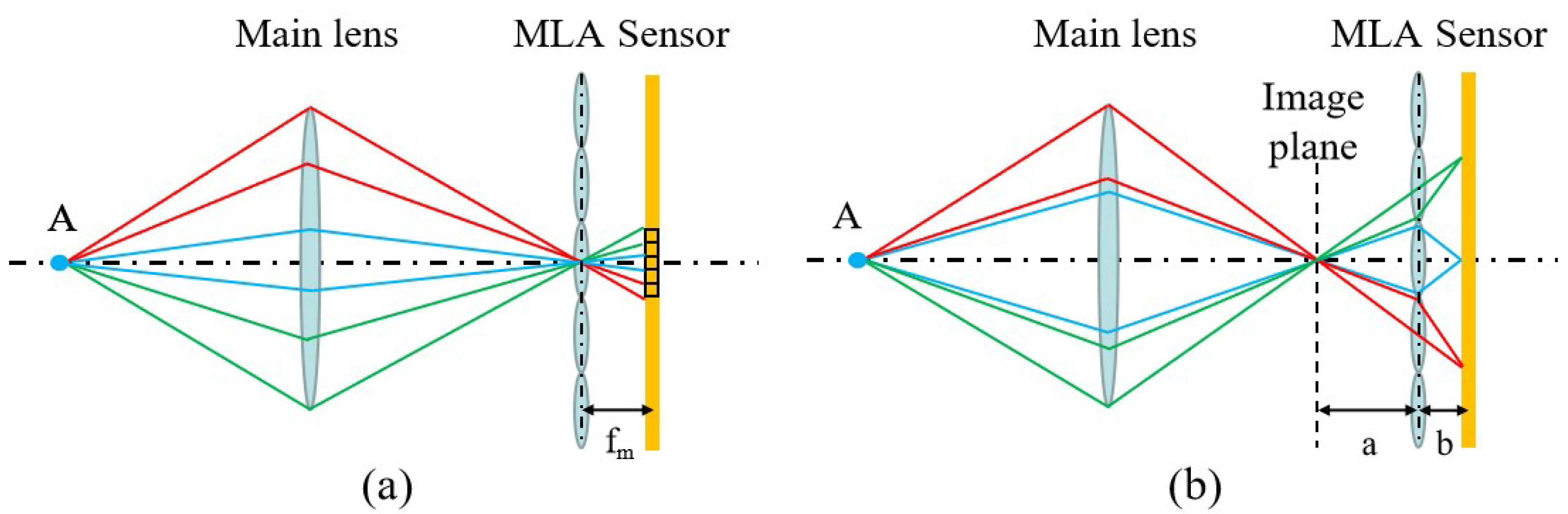
Figure 2. Measurement fundamentals of the light field camera. (a) The fundamental of the standard light field camera. (b) The fundamental of the focused light field camera.
The basic principle of the focused light field camera is shown in Figure 2b, where an array of microlenses is placed behind the image plane of the object point, enabling secondary imaging of the image from the primary lens to the sensor position. The light from Point A converges before the microlens array and continues to propagate forward to be imaged by different microlenses. The point is imaged secondarily by different microlenses to split the primary lens. Thus, its angular resolution depends on how many microlenses the image point can be secondarily imaged by, and no longer on the number of pixels corresponding to a single microlens. The angular resolution in one direction is a/b, and the distance of the primary image plane from the microlens array is a, while the distance of the sensor from the microlens array is b. They satisfy the Gaussian imaging relation for the focal length of the microlens.
Furthermore, the light field camera can be considered a camera array and is able to recover images from different views. This section provides a concise overview of the light field camera method for recovering multi-view images, along with the computation of the baseline and focal length for a comparable camera array. By converting to a camera array, the readers will gain a more-intuitive understanding and simplified calculations of the measurement system’s parameters, including the depth of field, resolution, field of view, and so on.
Figure 3a shows the corresponding camera array calculation for a standard light field camera. Each pixel behind a microlens corresponds to a view, and the combination of pixels corresponds to the same position of each microlens in an image in one viewpoint. As a result, the number of cameras is equal to the number of pixels corresponding to one microlens imaging region. Therefore, the equivalent camera’s optical center is defined as the intersection of the imaging rays of a sub-aperture image at the main surface of the main lens. Furthermore, the geometrical relation can be used to compute the baseline length bL and the focal length f of the camera array, which can be found in the literature [16][17].
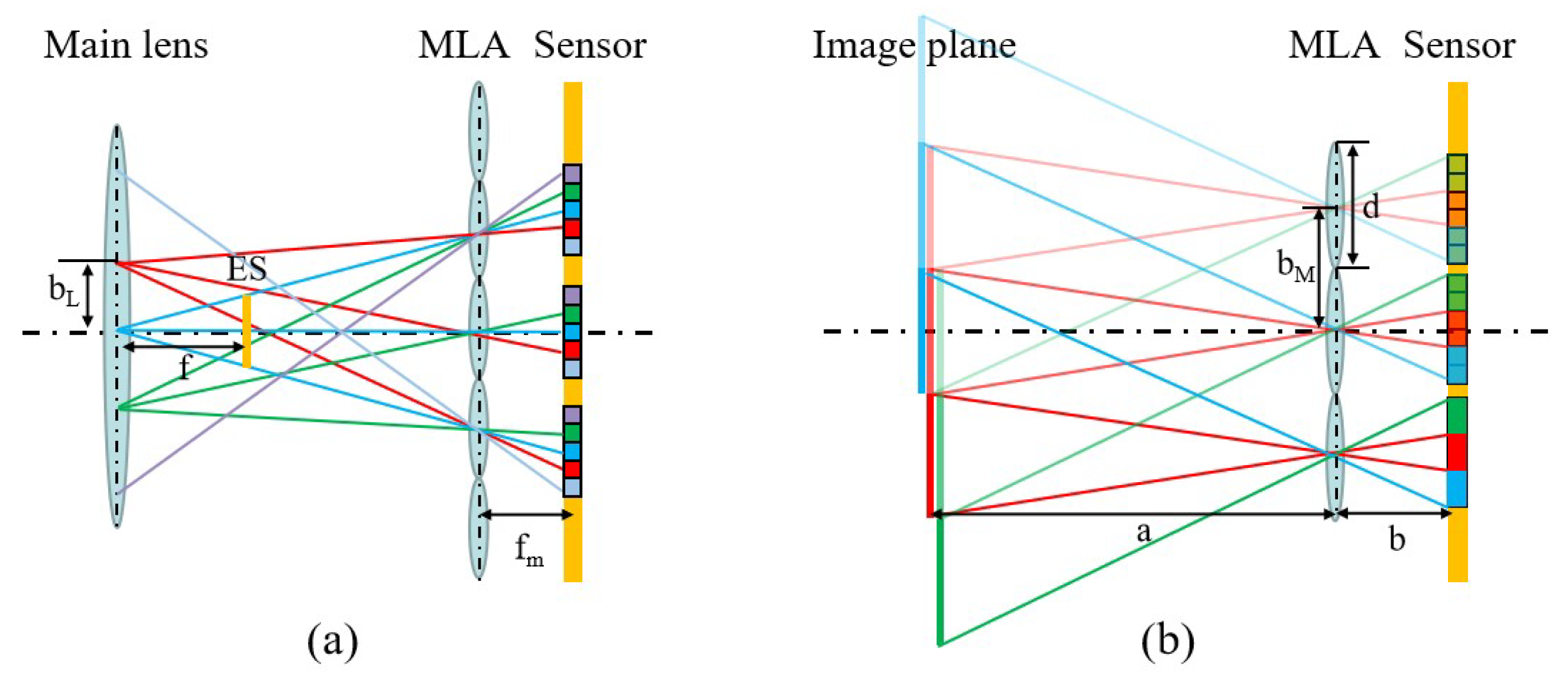
Figure 3. The schematic diagram of the equivalent camera array. (a) The diagram of the standard light field camera. (b) The diagram of the focused light field camera.
The equivalent camera array calculation of the focused light field camera is shown in Figure 3b. The different microlenses of the focused light field camera observe the point of the primary imaging plane, which can be directly equated to the camera. Subsequent transformations can further equate the light field camera to a camera array. This figure only traces the light to the primary imaging plane of the main lens. The primary imaging plane is continuously divided according to the size of the microlens array, and each region imaged by the microlens array will be a patch. Different division (red, green, and blue) corresponds to a different patch. By combining the patches of the same segmentation in order, an image from one viewpoint can be obtained. The camera baseline bM and the focal length fm in this figure are equal to the diameter of the microlens (d) and the distance b between the microlens and the sensor, respectively. The number of equivalent cameras in one direction is a/b. The equivalent camera array parameters of the whole light field camera can be subsequently obtained by geometric transformation.
2.3. Light Field Camera Design
To ensure the measurement accuracy and the proper application of the light field camera, it must be designed appropriately. The selection of the parameters of the light field camera was well described by M. Diebold et al. [18] and S. Shi et al. [19]. The structural design starts with an assessment of the measurement needs, weighing the trade-offs between spatial and angular resolution, then selecting the appropriate type of light field camera. After that, the core components of the light field camera such as the image sensor, the microlens array, and the main lens are selected and designed. The selection of the main lens is often based on the working distance, and it is preferable that the aperture be adjustable to satisfy the F-matching between the main lens and the microlens array [9]. Diebold equated the light field camera to a camera array and limited the parameters of the light field camera from two perspectives, which are the depth and the field of view. The first is the constraint of depth versus parallax. For instance, to compute orientation using the structure tensor, the disparity must lie in a symmetric 2 px range. This parameter restricts the camera array’s focal length, baseline, and pixel spacing. When they are fixed, the object must be in the range from Z+ (distal) to Z− (proximal). In addition to the depth constraint, a specific field of view within the measurement distance is also considered to ensure that all cameras can observe all parts of the target scene. Furthermore, as shown in Figure 4, a Frustum space can be defined to determine the image space of the light field camera so that it contains the object to be measured. Not only that, after meeting the above conditions, it is also necessary to consider the sensor frame rate, as well as the resolution requirements. After determining the sensor size to meet the field of view, the sensor resolution should be selected as large as possible to enhance the measurement accuracy. However, it should be noted that, often, the frame rate of high-resolution cameras will decline. Therefore, it is not very practical in some of the requirements of high dynamic measurement occasions. Therefore, the trade-off between the frame rate and camera resolution also needs to be made according to the measurement needs. In addition, Shi et al. also discussed the mechanical structure of the light field camera mounting design, which can be referred to by readers who need it.
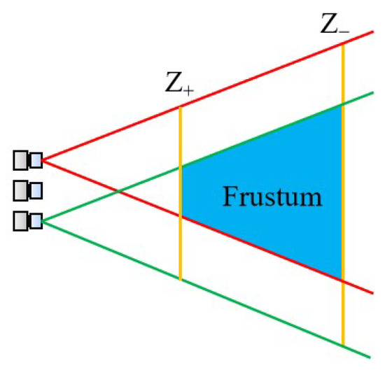
Figure 4. The frustum resulting from a designed light field camera setup [18].
References
- Wang, Y.; Guo, H. Machine vision and applications. Appl. Mech. Mater. 2018, 457, 1377–1380.
- Patel, K.K.; Kar, A.; Jha, S.; Khan, M. Machine vision system: A tool for quality inspection of food and agricultural products. J. Food Sci. Technol. 2012, 49, 123–141.
- Marr, D. Vision: A Computational Investigation into the Human Representation and Processing of Visual Information; MIT Press: Cambridge, MA, USA, 2010.
- Wang, Y.; Chen, T.; He, Z.; Wu, C. Review on the machine vision measurement and control technology for intelligent manufacturing equipment. Control Theory Appl. 2015, 32, 273–286.
- Bodin, P.; Noteborn, R.; Larsson, R.; Karlsson, T.; D’Amico, S.; Ardaens, J.S.; Delpech, M.; Berges, J.-C. The prisma formation flying demonstrator: Overview and conclusions from the nominal mission. Adv. Astronaut. Sci. 2012, 144, 441–460.
- Christian, J.A.; Cryan, S. A survey of lidar technology and its use in spacecraft relative navigation. In Proceedings of the AIAA Guidance, Navigation, and Control (GNC) Conference, Boston, MA, USA, 19–22 August 2013; p. 4641.
- Wang, P. Research on comparison of lidar and camera in autonomous driving. J. Phys. Conf. Ser. 2021, 2093, 012032.
- Broggi, A.; Grisleri, P.; Zani, P. Sensors technologies for intelligent vehicles perception systems: A comparison between vision and 3d-lidar. In Proceedings of the 16th International IEEE Conference on Intelligent Transportation Systems (ITSC 2013), The Hague, The Netherlands, 6–9 October 2013; pp. 887–892.
- Ng, R.; Levoy, M.; Brédif, M.; Duval, G.; Horowitz, M.; Hanrahan, P. Light Field Photography with a Hand-Held Plenoptic Camera. Ph.D. Thesis, Stanford University, Stanford, CA, USA, 2005.
- Adelson, E.H.; Wang, J.Y. Single lens stereo with a plenoptic camera. IEEE Trans. Pattern Anal. Mach. Intell. 1992, 14, 99–106.
- Lumsdaine, A.; Georgiev, T. The focused plenoptic camera. In Proceedings of the 2009 IEEE International Conference on Computational Photography (ICCP), San Francisco, CA, USA, 16–17 April 2009; pp. 1–8.
- Georgiev, T.G.; Lumsdaine, A. Depth of field in plenoptic cameras. Eurographics 2009, 11814, 1–4.
- Georgiev, T.; Lumsdaine, A. The multifocus plenoptic camera. In Digital Photography VIII; SPIE: Bellingham, WA, USA, 2012; Volume 8299, pp. 69–79.
- Xu, S.; Lu, S.; Hou, Y.; Shi, S. Accurate 3d geometry measurement for non-cooperative spacecraft with an unfocused light field camera. J. Syst. Eng. Electron. 2022, 33, 11–21.
- Zhu, S.; Lai, A.; Eaton, K.; Jin, P.; Gao, L. On the fundamental comparison between unfocused and focused light field cameras. Appl. Opt. 2018, 57, A1–A11.
- Mignard-Debise, L.; Restrepo, J.; Ihrke, I. A unifying first-order model for light field cameras: The equivalent camera array. IEEE Trans. Comput. Imaging 2017, 3, 798–810.
- Hahne, C.; Aggoun, A.; Velisavljevic, V.; Fiebig, S.; Pesch, M. Baseline and triangulation geometry in a standard plenoptic camera. Int. J. Comput. Vis. 2018, 126, 21–35.
- Diebold, M.; Blum, O.; Gutsche, M.; Wanner, S.; Garbe, C.; Baker, H.; Jähne, B. Light-field camera design for high-accuracy depth estimation. In Videometrics, Range Imaging, and Applications XIII; SPIE: Bellingham, WA, USA, 2015; Volume 9528, p. 952803.
- Shi, S.; New, T. Development and Application of Light-Field Cameras in Fluid Measurements; Springer Nature: Berlin/Heidelberg, Germany, 2022.
More
Information
Contributors
MDPI registered users' name will be linked to their SciProfiles pages. To register with us, please refer to https://encyclopedia.pub/register
:
View Times:
2.5K
Revisions:
2 times
(View History)
Update Date:
14 Aug 2023
Table of Contents


Notice
You are not a member of the advisory board for this topic. If you want to update advisory board member profile, please contact office@encyclopedia.pub.
OK
Confirm
Only members of the Encyclopedia advisory board for this topic are allowed to note entries. Would you like to become an advisory board member of the Encyclopedia?
Yes
No
${ textCharacter }/${ maxCharacter }
Submit
Cancel
Back
Comments
${ item }
|
${ item.createdUser.fullName }
${ item.createdAt }
${ item.vote }
${ item.reply }
Delete
${ reply.createdUser.fullName }
${ reply.createdAt }
${ reply.vote }
Delete
There is no reply to this comment~
${ item.replyTextCharacter }/${ item.replyMaxCharacter }
Submit
Cancel
More
No more~
There is no comment~
${ textCharacter }/${ maxCharacter }
Submit
Cancel
${ selectedItem.replyTextCharacter }/${ selectedItem.replyMaxCharacter }
Submit
Cancel
Confirm
Are you sure to Delete?
Yes
No