Your browser does not fully support modern features. Please upgrade for a smoother experience.
Submitted Successfully!
 +1 credit
Thank you for your contribution! You can also upload a video entry or images related to this topic.
For video creation, please contact our Academic Video Service.
| Version | Summary | Created by | Modification | Content Size | Created at | Operation |
|---|---|---|---|---|---|---|
| 1 | Tariq Amin Khan | -- | 3582 | 2023-08-09 20:11:53 | | | |
| 2 | Rita Xu | Meta information modification | 3582 | 2023-08-10 04:13:32 | | |
Video Upload Options
We provide professional Academic Video Service to translate complex research into visually appealing presentations. Would you like to try it?
Cite
If you have any further questions, please contact Encyclopedia Editorial Office.
Afridi, S.; Khan, T.A.; Shah, S.I.A.; Shams, T.A.; Mohiuddin, K.; Kukulka, D.J. Fluidic Thrust Vectoring in Jet Engine Nozzles. Encyclopedia. Available online: https://encyclopedia.pub/entry/47854 (accessed on 25 July 2026).
Afridi S, Khan TA, Shah SIA, Shams TA, Mohiuddin K, Kukulka DJ. Fluidic Thrust Vectoring in Jet Engine Nozzles. Encyclopedia. Available at: https://encyclopedia.pub/entry/47854. Accessed July 25, 2026.
Afridi, Saadia, Tariq Amin Khan, Syed Irtiza Ali Shah, Taimur Ali Shams, Khawar Mohiuddin, David John Kukulka. "Fluidic Thrust Vectoring in Jet Engine Nozzles" Encyclopedia, https://encyclopedia.pub/entry/47854 (accessed July 25, 2026).
Afridi, S., Khan, T.A., Shah, S.I.A., Shams, T.A., Mohiuddin, K., & Kukulka, D.J. (2023, August 09). Fluidic Thrust Vectoring in Jet Engine Nozzles. In Encyclopedia. https://encyclopedia.pub/entry/47854
Afridi, Saadia, et al. "Fluidic Thrust Vectoring in Jet Engine Nozzles." Encyclopedia. Web. 09 August, 2023.
Copy Citation
Thrust vectoring innovations are demonstrated ideas that improve the projection of aerospace power with enhanced maneuverability, control effectiveness, survivability, performance, and stealth. Thrust vector control systems following a variety of concepts have been considered for modern aircraft and missiles to enhance their military performance. Short Take-off and Landing (STOL) and control effectiveness at lower aircraft speeds can be achieved by employing Fluidic Thrust Vectoring Control (FTVC).
thrust vectoring
fluidic thrust vectoring
throat skewing
1. Introduction
Every time, new technologies emerge that are innovative enough to dramatically change the nature of military operations. For high-performance aircraft, thrust vectoring technology has emerged so profoundly that it has redefined traditional aircraft design methods and the use of the aircraft itself. Thrust vectoring technology offers many advantages in terms of maneuverability, control effectiveness, survivability, performance, and stealth characteristics of the aircraft. It is a technique that can provide effective forces and moments, making take-off and landing requirements easier, even at low dynamic pressure. Thrust vectoring provides additional thrust and allows pitching, yawing, and rolling movements by changing the line of thrust.
Thrust vectoring (TV) technology works on the principle of deflecting the thrust direction of the aircraft. It relies on a working fluid, or a source mounted on the aircraft, and an engine exhaust nozzle providing a passage for the fluids. For providing the maximum thrust possible to the aircraft, the nozzle designs must ensure the requirement of thrust, cost, mission profile, and weight of the aircraft. Until now, nozzles for thrust vectoring have been technologically advanced from single-axis to multi-axis systems. Single-axis convergent-divergent nozzles deflect the thrust in the pitch direction, whereas multi-axis convergent-divergent nozzles are capable of deflecting thrust around all three-body axis. These nozzles actively complement or even eliminate the use of control surfaces [1]. To date, TV is achieved in an aircraft using two methods. The traditional method involves mechanical means to deflect the direction of flow of the exhaust gases, whereas the most recent method involves fluidic-based thrust vectoring techniques.
Mechanical thrust vectoring (MTV) is a technique achieved mechanically by deflecting the engine nozzle to alter the direction of thrust with the use of actuators and gimbaling mechanisms. Although it produces effective TV, the thrust vectoring configurations become heavy, complex, and expensive. To overcome the complexity and integration inefficiency of MTV, fluidic thrust vectoring (FTV) techniques were developed and investigated. FTV is a technique that uses a secondary flow source for controlling the exhaust flow of the engine nozzle. Fluidic-based methods provide the advantage of reduced weight, higher reliability, and engine airframe integration [2][3][4]. Fluidic injection for throttling and vectoring was explored in the 1950s for application to rocket nozzle systems. It actively controlled the primary flow deflection by penetrating the secondary fluid into the divergent section of the rocket nozzle [5][6][7]. However, its interest was lost. It was in the 1990s when researchers were again attracted to FTV due to its fascinating thrust vectoring performance characteristics. The research concluded that FTV was capable of achieving the same vectoring control as MTV but with 50% reduced weight and cost. Several FTV controls were investigated to deflect the primary flow. It was observed experimentally that a small variation in the nozzle area could result in an entire flow modification of the nozzle [8][9][10]. FTV provides aircraft with several advantages. Firstly, it requires no moving part, which leads to reduced weight and complexity of the system. Secondly, for high-temperature conditions, an optimal nozzle can be designed, which can reduce drag and radar cross-section. FTV is more desirable due to its quick integration into existing systems [11][12]. In dry and afterburner cruise operating conditions, fixed exhaust nozzles demonstrated significant thrust vectoring capabilities [13][14]. These benefits have led to a vast investigation and development of FTV techniques. To date, depending upon investigations, FTV controls are divided into seven control systems. These control systems are Shock Vector Control, Bypass Shock Vector Control, Counter Flow Control, Co-Flow Control, Throat Skewing control, Dual Throat Nozzle Control, and Bypass Dual Throat Nozzle Control. Among all these vectoring controls, counter-flow control works on the principle of suction to control the primary flow deflection. However, the rest of the control techniques depend upon the principle of blowing to control the primary flow deflection. Different methods of fluidic thrust vectoring control are represented in Figure 1.

Figure 1. History of fluidic thrust vectoring controls techniques.
2. Shock Vector Control (SVC)
Shock vector control is an FTV technique that introduces a secondary fluidic flow injection in the divergent portion of the convergent-divergent nozzle. The disturbance caused by this injected flow generates an oblique shock wave due to the low-pressure region downstream of the injection port. The interaction of the oblique shock wave with primary flow deflects the flow supersonically, thus resulting in thrust vectoring. A schematic of SVC is shown in Figure 2.
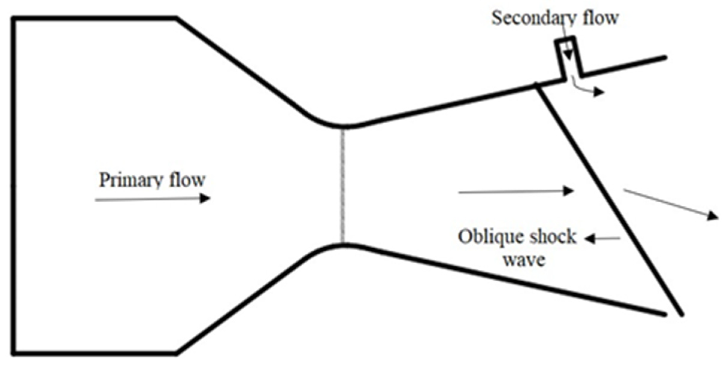
Figure 2. Schematic of Shock Vector Thrust Vectoring Control causing obliques shock wave by introducing a secondary flow injection in the supersonic portion of the nozzle.
2.1. Effect of NPR and SPR
A series of experiments were performed for a nozzle pressure ratio (NPR) of 10–30, along with different secondary pressure ratios (SPR) for a supersonic nozzle [15]. The maximum vectoring angle reported was 5°, significantly less than previous investigations carried out on the SVC technique. A thrust ratio of 0.88 was observed in both cases (NPR = 20–30). It was believed that the over-expanded nature of nozzle flow might have resulted in such a low value [16]. The effects of secondary injection on SVC performance were investigated for a range of NPR up to 10 with an SPR value from 0.4 to 1. For NPR = 4.6 and SPR = 0.7 and 1, the thrust vectoring angle achieved was 7.5°. NPR values of 2.5 and above showed a good agreement between numerical and experimental data, but NPR values less than 2.5 (highly over-expanded flows) showed a disagreement [17]. TV angle of 4.4° at NPR = 3 and thrust coefficient of 0.891 was achieved as the best TV efficiency. The thrust coefficient relates to the ratio of resultant thrust to ideal thrust. It determines the amplification of thrust during flow expansion. Injection parameters such as location, angle, length-to-width ratio, and momentum flux ratio (J) were investigated for NPR = 4.6. It was observed that increasing momentum flux and length-to-width ratio caused an increase in TV angle [18]. For NPR = 3 and 4.6, the largest TV angle achieved was 17.2° and 17.6°. The largest deflection angle was achieved when the injection location moved upstream and decreased when it moved downstream. The injection angle also played a vital role in the deflection angle [19]. The effect of secondary flow for an NPR = 4–10 with SPR = 1–2 at two different injection locations was investigated. The result indicated that SPR had a positive impact on TV moments [20]. Two different nozzle models were compared to evaluate the performance of FTV for different NPR = 3–10 and SPR = 1–3 with two injection locations [21]. The internal performance of a 2D nozzle was investigated for NPR up to 10 and SPR up to 2.7. Two shock waves were generated, a weak shock at the upstream of injection and a stronger wave at the injection interface. The primary flow was deflected twice, but the stronger shock resulted in deflecting the flow [22].
2.2. Transverse Injection
The SVC technique has the ability to provide large TV angles by generating a shock system. However, due to operating in over-expanded conditions, SVC also suffered from over-expansion losses in order to achieve high TV angles [23][24]. SVC-induced problems related to thrust losses due to the penetration of secondary flow and the formation and interaction of oblique shock with the primary flow. For achieving maximum thrust vectoring angle with minimum thrust losses, an optimized secondary injection design based on transverse injection flow was conceived [25]. Some researchers [26][27] investigated the transverse injection cases; the result indicated that separation and shock interaction occur along the deflected jets. Due to the secondary injected flow, unbalanced forces act in the divergent section [28]. An experimental study was carried out to investigate yaw thrust vectoring for a low subsonic flow regime with varying secondary injection momentum ratios. The study found that the vectoring angle increases with increasing the momentum ratio of the secondary flow [29]. A study conducted compared the Reynolds stress and k-ε turbulence model with experimental data. The Reynolds stress model predicted the experimental result accurately compared to k-ε. As pressure ratios increased, Reynolds stress model results became less consistent [30]. To evaluate the performance, two- and three-dimensional cases were proposed, investigated, and numerically modeled. These models were experimentally complemented and improved numerically [31]. Until now, there have been many optimal strategies developed for SVC. However, an optimal application for transverse injection is still under investigation.
2.3. Slot Injection
For SVC, an axisymmetric conical supersonic nozzle has also been theoretically, experimentally, and numerically studied [32]. The geometric parameters of 3D circular sonic injection into the supersonic region of the nozzle were investigated for NPR of 37.5 with variable SPR. The results indicated that TV through secondary flow was dominantly affected by the inclination and position of injection in the nozzle [33]. A circular injector port was used for penetrating the secondary flow in the divergent part of the nozzle and could generate a strong shock to deflect the primary flow. Figure 3 signifies the schematic of the flow field with slot injection. When a secondary flow was injected into the primary flow, the flow encountered a bow shock wave with various viscous and boundary layer interactions. Due to an adverse pressure gradient, weak shock waves appeared at the initial separation point [34][35]. However, as the boundary layer got close to the secondary fluidic injection port, the separation deepened and allowed the formation of a strong bow shock wave. This strong bow shock wave was caused due to the compression fan interaction. The region of recirculating bubbles was observed both upstream and downstream of the nozzle, as well as the injected upstream region [36][37]. The primary flow, when crossing from the separation point, attached the bow shock to itself and continued its motion forward. Sometimes, the interaction between the primary and secondary flow caused the formation of a more complex reflection of the shock wave, including surface effects [38][39].
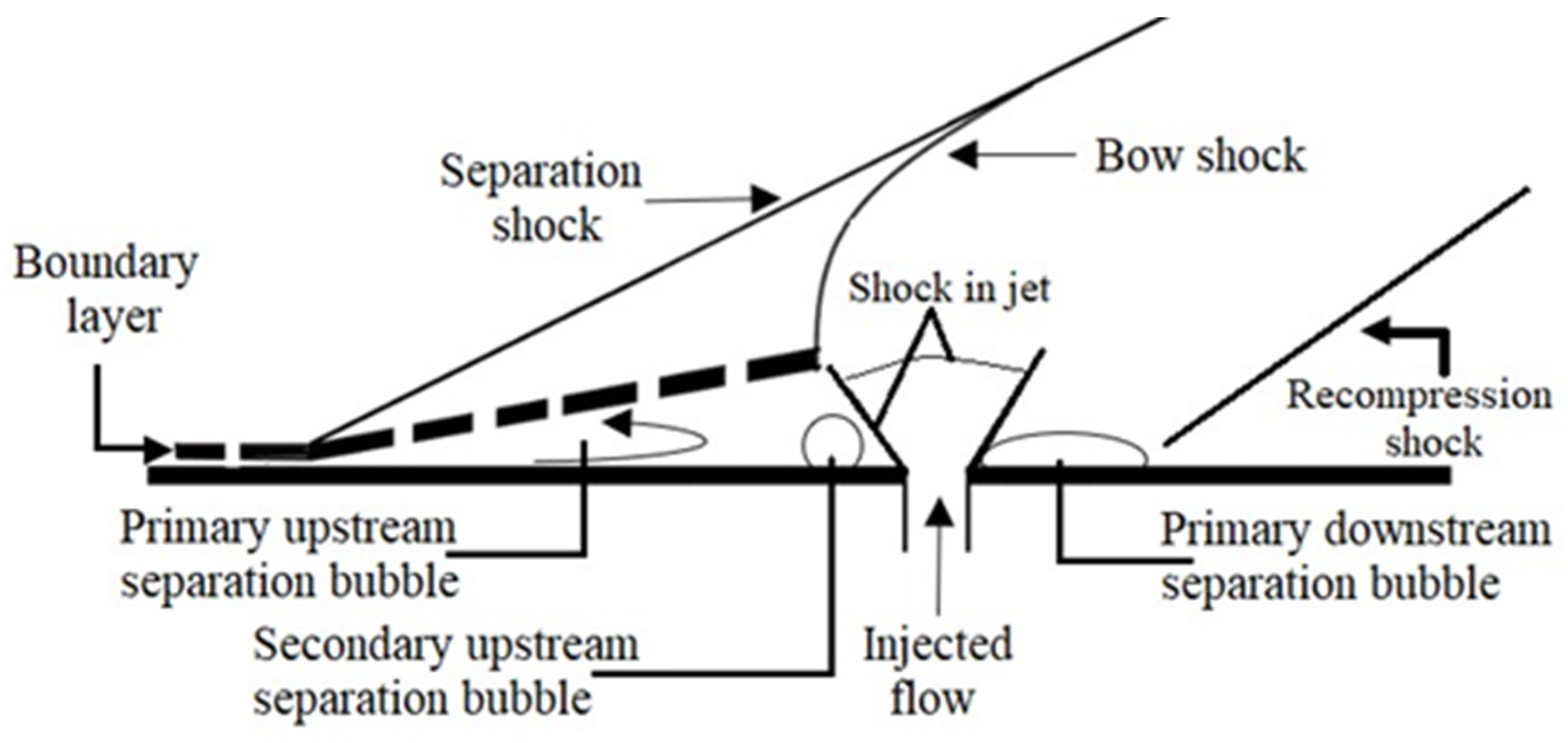
Figure 3. Schematic of a flow field with slot injection.
2.4. Injection Configurations
A 2D SVC nozzle with secondary injection located at 68.8% of the divergent section of the nozzle was analyzed. The parameters considered were NPR = 6–16, SPR = 0.6, 0.8, 1, 1.2, secondary angle of 90° and 130°, along with 7, 9, and 13 orifice injection configurations. The result indicated that the TV angle for the 19 orifices injection configuration was greater compared to the 7 and 13 orifices. It was concluded that the thrust coefficient decreased with decreasing the number of injection orifices for different SPRs. Although the 19 orifices had a better vectoring angle than the 13 and 7 orifices, it was still less than the vectoring angle obtained from a single injection slot. For obtaining a larger vectoring angle in SVC, single-slot injection was a better option [40]. The effects of multiple port injections for a 2D non-axisymmetric nozzle were investigated both experimentally and computationally. The results demonstrated the benefits of using multiple injection ports. For NPR less than 4 and higher SPR, increasing the injection port from one to two resulted in improved TV performance. At the same time, no benefits were recorded for NPR values greater than 4 [41]. A 3D study using an orifice injector demonstrated that the deviation angle increases from 5.49° to 9.23° with increasing SPR from 0.667 to 1.167 [42].
2.5. Effect of Hot and Cold States
A plenum above the span-wise slot for a 2D nozzle was investigated. The plenum was used for facilitating the secondary flow injection [43]. The effect of cold and hot states on the thrust was investigated. The operation included five states: no nozzle, fixed nozzle, secondary injection in the throat area, secondary injection in the divergent area, and secondary injection in both the throat and divergent area. At secondary pressure of 0.5 MPa, the thrust obtained for the five states ranged between 27.3 N to 50.9 N. The result demonstrated that cold injection through secondary injection not only enhanced the thrust performance but was also capable of reducing the over-expansion and under-expansion losses [44].
2.6. Bypass Flow Injection
A bypass flow injection has been investigated to control the deflection angle [45][46][47][48]. To minimize the influence of secondary injection and to maximize the thrust vectoring angle with minimal thrust loss, a bypass passage flow SVC was conceived. A control valve was used to control the bypass flow rate. It was observed that with increasing the bypass flow rate, there was an increase in thrust vectoring angle as well. With a bypass flow of less than 10%, 10° thrust vectoring was achieved [49]. Figure 4 signifies the bypass SVC schematic for TV.
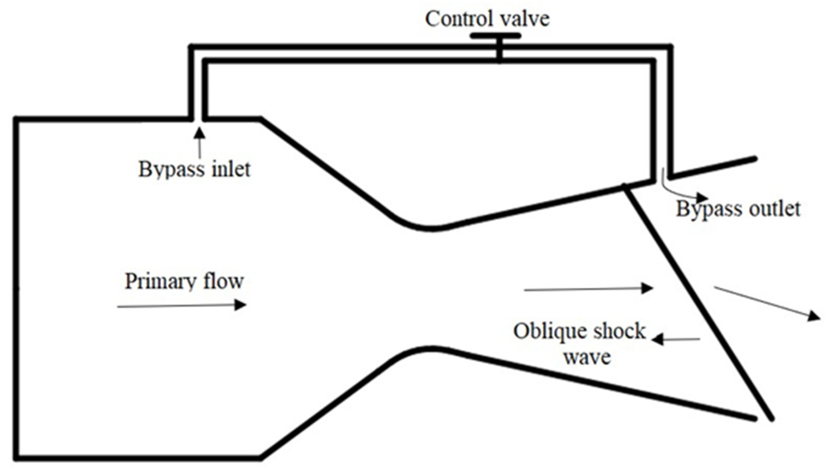
Figure 4. Representation of Bypass Shock Vector Thrust Vectoring Control with bypass passage flow.
2.7. Injectors
The asymmetric two-dimensional nozzle was investigated for different kinds of injectors. Two adjacent sonic injections were examined by NASA [41]. A single injector for the SVC configuration was observed for NPR = 4.6 and 8.78, along with SPR values of 0, 0.7, and 1. The best TV angle achieved was about 6.9°, providing an efficiency of 1.7 with a 4% injection mass flow rate and 0.96 thrust coefficient [50]. Aerodynamic effects on FTV were also examined. Results were computed for free stream and static flow conditions. Compared to static flow conditions, TV performance and efficiency decreased for free stream flow [15]. The effect of secondary injection reaction heat on TVC was also explored computationally and experimentally. For primary and secondary flow, methane and air reaction were used for the reaction process [51]. The effect of the different gas injectors on the main nozzle was investigated. The gases included CO2, argon, and helium for SPR = 1 and MFR = 0.076. Helium gas was indicated to produce large TV angles of 16.2° and 15.15° [52].
FTV performance for a 2D single expansion ram nozzle was numerically calculated. The impact of the suction tunnel position, angle, and width was also analyzed [53]. Different models and designs were investigated and proposed for the axisymmetric nozzle to achieve better performance for the vectoring control system [54]. In summary, many parameters have been examined for fluidic SVC. A few parameters and their effects on TV for different configurations are compiled in Table 1.
Table 1. Parameters affecting the shock vector control.
| Parameters | Effects | Ref |
|---|---|---|
| Mach | Increasing Mach would decrease TV efficiency | [55] |
| MFR | Decreasing MFR of nozzle would result in strong oblique shock wave | [32] |
| SPR | Increasing SPR improves TV angle, reduce response time, dynamic response, and increases the mass flow rate of secondary flow | [23] |
| NPR | Decreasing NPR with Mach number results in better TV angle and efficiency. Increasing NPR results in increased dynamic response and mass flow rate of nozzle flow but decreased fluidic injection efficiency | [25] |
| Injection angle | Decreasing injection angle results in increased dynamic response | [56] |
| J | Increasing J improves the TV angle and increases deflection angle | [18] |
A graphical representation of these parameters, which includes the effect of NPR, the effect of SPR, injection location, and injection angle, is presented in Figure 5. All the trends observed for these parameters were obtained from the data available in the literature. The trend for vectoring angle and vectoring coefficient at different NPR were observed in Figure 5a. Vectoring angle showed a decreasing trend with increasing NPR, whereas the thrust coefficient was observed to increase for NPR < 6.5 and decrease for NPR > 6.5. It was reported that increasing NPR resulted in eliminating the shock and improving the separation in the nozzle, which improved the thrust but degraded the vectoring angle [15][40]. Figure 5b refers to the trend of vectoring angle, vectoring efficiency, and thrust coefficient at different SPRs. An increase in vectoring angle was reported, whereas a decreasing trend for vectoring efficiency and thrust coefficient was observed. At larger SPR, the interaction of shock with the upper wall induced thrust losses and resulted in larger pressure loss [32]. Similarly, Figure 5c reported an increasing trend in the vectoring angle with increasing injection angle and injection location. Increasing the injection angle and injection location had a negative impact on vectoring efficiency and thrust coefficient [32][40].

Figure 5. Effect of (a) NPR, (b) SPR, (c) Injection angle and injection location on SVC. These data were extracted from the previous investigations carried out on SVC.
SVC has widely investigated thrust vectoring control until now. It was reported that SVC achieves a higher vectoring angle, but the shock formation degrades the performance of the nozzle. Multiple turbulence models were investigated for SVC. It was reported that SST k-ω was able to predict the separation position and pressure rise in agreement with the experimental values. The potential downside of using SVC is the creation of shock which introduces performance losses and structural damage due to the shock boundary layer interaction in the nozzle.
3. Counter Flow Control (CFC)
The counter-flow thrust vectoring technique involves a secondary fluidic flow penetrated in the opposite direction of the primary flow. Usually, in the counterflow technique, the application of suction creates a secondary fluidic flow stream and produces an asymmetric flow in the primary fluid. The difference between co-flow and counter-flow thrust vectoring control is that the former involves momentum injection, while the latter uses momentum removal for controlling the primary flow. CFTV can achieve large TV angles by using suctions between the nozzle’s trailing edge and an aft collar. Figure 6 details the CFTV schematic for the TV.
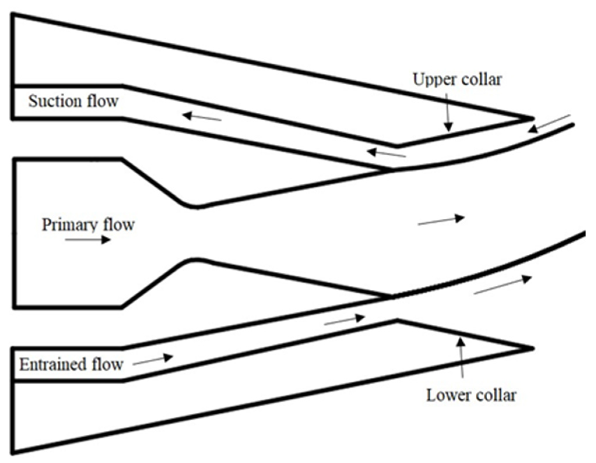
Figure 6. Schematic of Counterflow Thrust Vectoring Control with collar configuration.
3.1. Shear Layer CFTV
Several theoretical and numerical investigations on CFTV control have been carried out. A new calculation on a 3D rectangular nozzle current CFTV shear layer system for different mainstream temperatures was examined. It was found that by increasing the mainstream temperature, the Mach number increased, and the TV angle gradually declined. However, this experiment reported that the mainstream temperature doesn’t significantly affect the thrust coefficient [57]. Several other parameters were studied for CFTV, which included collar length, collar radius, and the gap height between the primary and secondary flow. The results for the shear layer CFTV technique provided a more controllable region than the co-flow FTV technique [58][59]. A multi-axis diamond-shaped nozzle CFTV was investigated for achieving TV for a Mach number of 2. The maximum deflection achieved was 15°. A comparison of a multi-axis and a single-axis was also inspected. It was found that a single-axis CFTV system was more efficient in producing TV and had reasonably linear behavior [60]. In CFTV, for steering the jet, no moving parts and surfaces were in contact with the moving fluids. However, the drawback of the use of the CFTV application was restricted due to engine integration, hysteresis, and additional equipment for suction [61].
3.2. Collar Geometry
By increasing the gap height, the suction MFR also increased. A proper range of collar length was required for side forces to act adequately on the primary flow. Different experiments on collar geometry indicated that without a proper collar, control flow was not efficient [62]. Being said, the collar played a vital role in ensuring the optimal efficiency of the counterflow TV system. The collar allowed a path for secondary fluid to flow, which created a mixing layer across the collar area. By disrupting the continuity of the operation, the collar was found to be responsible for creating hysteresis and bi-stability problems. For a certain condition at the nozzle, the jet attached to the wall due to a bi-stability problem reached a stable equilibrium [56]. Effects of geometric parameters (slot width, length of the collar) on the Laval nozzle were numerically studied. A critical length of collar was obtained between 0.19–0.2 m, and the slot width varied between 0.017–0.02 m [63]. For implementing CFTV in the aircraft propulsion system, a well-established rectangular jet for a Mach number of 1.4 was investigated [64]. For CFTV, a TV angle of 16° was achieved for a supersonic rectangular jet [65]. By designing the collar geometry properly, the Coanda effect could be avoided. A proper collar design must consider the stability of the aircraft, TV efficiency, and continuous performance at a high TV angle. CFTV was able to produce a maximum vector angle of 15° at NPR = 5. The thrust coefficient at NPR of 5 was 0.2. At NPR = 8, CFTV was able to achieve a vector angle of 12° with a 0.945 thrust coefficient [66]. It was concluded that adding a large collar to the CFTV control technology made it more efficient compared to other FTV techniques.
3.3. Effect of NPR
At different NPRs, the effects of various characteristics for a Mach number of 2.5 on TV performance for CFTV were investigated. For NPR = 15–17 and 18–20 values, at a constant SPR of 0.8, it was observed that with increasing the NPR, the primary MFR increased, and thus, the MFR of secondary flow decreased. For SPR of 0.9–0.6, a low value of secondary mass ratio (0.6%–2.3%) was reported. It was found that with a decreased value of SPR, an increased value of thrust loss was achieved. The deflection angle achieved for the SPR value of 0.6 was 5.5°. For an SPR value of 0.8, the MFR of secondary flow was obtained between 0.9% and 2.4% [56]. A study was conducted at an NPR range of 3.5–10 values for a collar length of 8 inches (100% and 50%) with different suction slot heights. When comparing 50% and 100% collars, the latter was found to produce the largest TV angle. Upon decreasing the slot height, the decreasing behavior of the resultant thrust ratio was obtained [67]. Several parameters have been examined for fluidic counterflow control. A graphical representation of the effect of SPR and collar length is presented in Figure 7. All the trends observed for these parameters were obtained from the data available in the literature. Vectoring angle showed a decreasing trend with increasing SPR, whereas the thrust coefficient was observed to increase with increasing SPR. At constant NPR = 17, the performance of vectoring angle and thrust coefficient reported was better for high Mach conditions. Another important parameter affecting the performance of CFC was collar length. A decreasing trend for vectoring angle and an increasing trend for thrust coefficient at varying collar lengths were observed [56][57].
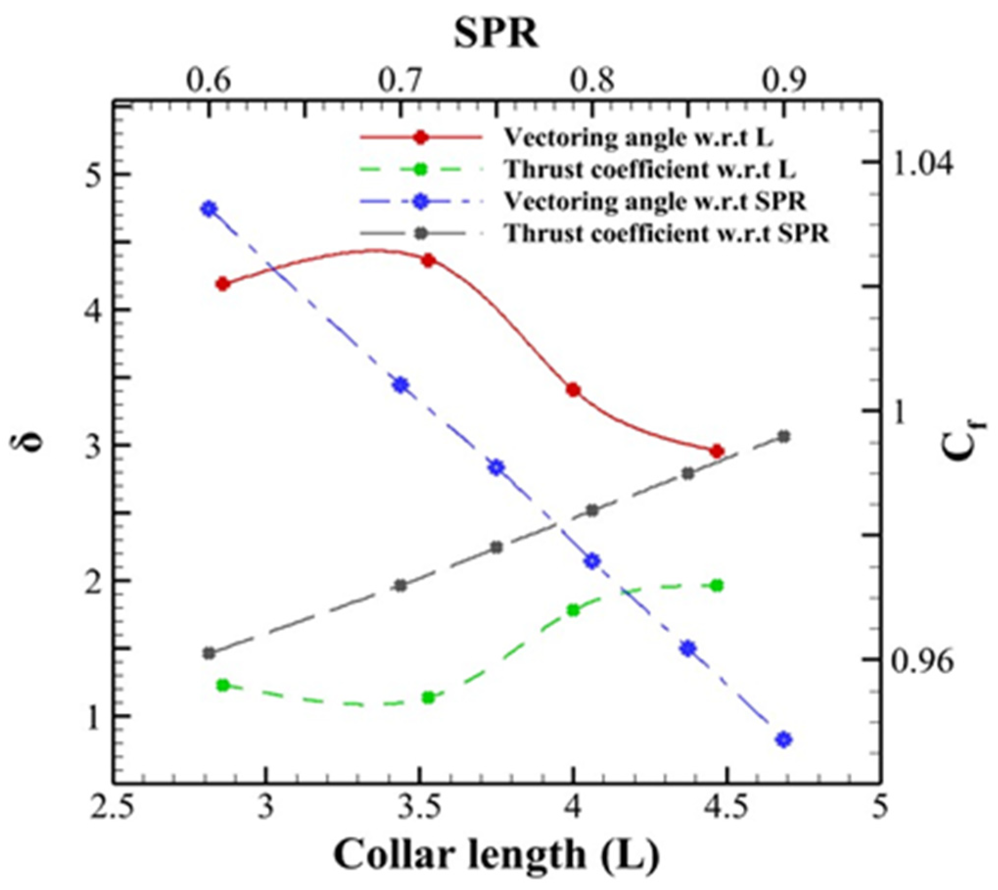
Figure 7. Comparison of the effect of SPR and collar length on CFC. These data were extracted from the previous investigations carried out on CFC.
References
- Ikaza, D. Thrust vectoring nozzle for modern military aircraft. In Proceedings of the 22nd Congress of International Council of the Aeronautical Sciences, Harrogate, UK, 27 August–1 September 2000.
- Francis, M.S. Air Vehicle Management with Integrated Thrust-Vector Control. AIAA J. 2018, 56, 4741–4751.
- Henderson, B. Fifty years of fluidic injection for jet noise reduction. Int. J. Aeroacoustics 2010, 9, 91–122.
- Hanumanthrao, K.; Ragothaman, S.; Kumar, B.A.; Prasad, M.G.; Kumar, V.S. Studies on fluidic injection thrust vectoring in aerospike nozzles. In Proceedings of the 49th AIAA Aerospace Sciences Meeting Including the New Horizons Forum and Aerospace Exposition, Orlando, FL, USA, 4–7 January 2011; p. 293.
- Wing, D.J. Static Investigation of Two Fluidic Thrust-Vectoring Concepts on a Two-Dimensional Convergent-Divergent Nozzle; National Aeronautics and Space Administration, Langley Research Center: Hampton, VA, USA, 1994; Volume 4574.
- Wing, D.J.; Giuliano, V.J. Fluidic thrust vectoring of an axisymmetric exhaust nozzle at static conditions. In Proceedings of the ASME Fluids Engineering Division Summer Meeting, Vancouver, BC, Canada, 22–26 June 1997; pp. 22–26.
- Broadwell, J.E. Analysis of the fluid mechanics of secondary injection for thrust vector control. AIAA J. 1963, 1, 1067–1075.
- Rifky, S. Return flight. Art Am. 2015, 103, 55–58.
- Cuppoletti, D.R.; Gutmark, E.J.; Hafsteinsson, H.E.; Eriksson, L.E.; Prisell, E. Analysis of Supersonic Jet Thrust with Fluidic Injection. In Proceedings of the 52nd Aerospace Sciences Meeting, National Harbor, MD, USA, 13–17 January 2014; p. 0523.
- Gamble, E.; DeFrancesco, R.; Haid, D.; Buckwalter, D. Fluidic nozzle to improve transonic pitch and thrust performance of hypersonic vehicle. In Proceedings of the 41st AIAA/ASME/SAE/ASEE Joint Propulsion Conference & Exhibit, Tucson, AZ, USA, 10–13 July 2005; p. 3501.
- Kral, L.D. Active Flow Control Technology; ASME Fluids Engineering Technical Brief; Washington University in St. Louis: St. Louis, MO, USA, 1999.
- Deere, K. Pab3d simulations of a nozzle with fluidic injection for yaw thrust-vector control. In Proceedings of the 34th AIAA/ASME/SAE/ASEE Joint Propulsion Conference and Exhibit, Cleveland, OH, USA, 13–15 July 1998; p. 3254.
- Anderson, C.; Giuliano, V.; Wing, D. Investigation of hybrid fluidic/mechanical thrust vectoring for fixed-exit exhaust nozzles. In Proceedings of the 33rd Joint Propulsion Conference and Exhibit, Seattle, WA, USA, 6–9 July 1997; p. 3148.
- Giuliano, V.; Wing, D. Static investigation of a fixed-aperture nozzle employing fluidic injection for multiaxis thrust vector control. In Proceedings of the 33rd Joint Propulsion Conference and Exhibit, Seattle, WA, USA, 6–9 July 1997; p. 3149.
- Deere, K. Computational investigation of the aerodynamic effects on fluidic thrust vectoring. In Proceedings of the 36th AIAA/ASME/SAE/ASEE Joint Propulsion Conference and Exhibit, Las Vegas, NV, USA, 24–28 July 2000; p. 3598.
- Neely, A.; Gesto, F.; Young, J. Performance studies of shock vector control fluidic thrust vectoring. In Proceedings of the 43rd AIAA/ASME/SAE/ASEE Joint Propulsion Conference & Exhibit, Cincinnati, OH, USA, 8–11 July 2007; p. 5086.
- Ferlauto, M.; Marsilio, R. Computational investigation of injection effects on shock vector control performance. In Proceedings of the 2018 Joint Propulsion Conference, Cincinnati, OH, USA, 9–11 July 2018; p. 4934.
- Wu, K.; Kim, H.D. Numerical study on the shock vector control in a rectangular supersonic nozzle. Proc. Inst. Mech. Eng. Part G J. Aerosp. Eng. 2019, 233, 4943–4965.
- Forghany, F.; Taeibe-Rahni, M.; Asadollahi-Ghohieh, A.; Banazdeh, A. Numerical investigation of injection angle effects on shock vector control performance. Proc. Inst. Mech. Eng. Part G J. Aerosp. Eng. 2019, 233, 405–417.
- Li, L.; Saito, T. Numerical and experimental investigations of fluidic thrust vectoring mechanism. Int. J. Aerosp. Innov. 2012, 4, 53–64.
- Li, L.; Saito, T. A survey of performance of fluidic thrust vectoring mechanisms by numerical and experimental studies. Int. J. Aerosp. Innov. 2013, 5, 51–60.
- Li, L.; Hirota, M.; Ouchi, K.; Saito, T. Evaluation of fluidic thrust vectoring nozzle via thrust pitching angle and thrust pitching moment. Shock. Waves 2016, 27, 53–61.
- Zmijanovic, Z.; Lago, V.; Palerm, S.; Oswald, J.; Sellam, M.; Chpoun, A. Thrust shock vector control of an axisymmetric cd nozzle via transverse gas injection. In Proceedings of the 28th International Symposium on Shock Waves, Manchester, UK, 17–22 July 2011; Springer: Berlin/Heidelberg, Germany, 2012; pp. 171–177.
- Saito, T.; Fujimoto, T. Numerical studies of shock vector control for deflecting nozzle exhaust flows. In Shock Waves; Springer: Berlin/Heidelberg, Germany, 2009; pp. 985–990.
- Deng, R.; Kong, F.; Kim, H.D. Numerical simulation of fluidic thrust vectoring in an axisymmetric supersonic nozzle. J. Mech. Sci. Technol. 2014, 28, 4979–4987.
- Spaid, F.W.; Zukoski, E.E. A study of the interaction of gaseous jets from transverse slots with supersonic external flows. AIAA J. 1968, 6, 205–212.
- Schetz, J.A.; Billig, F.S. Penetration of gaseous jets injected into a supersonic stream. J. Spacecr. Rocket. 1966, 3, 1658–1665.
- Shi, J. Performance estimation for fluidic thrust vectoring nozzle coupled with aero-engine. In Proceedings of the 50th AIAA/ASME/SAE/ASEE Joint Propulsion Conference, Cleveland, OH, USA, 28–30 July 2014; p. 3771.
- Sekar, T.C.; Kushari, A.; Mody, B.; Uthup, B. Fluidic thrust vectoring using transverse jet injection in a converging nozzle with aft-deck. Exp. Therm. Fluid Sci. 2017, 86, 189–203.
- Chenault, C.F.; Beran, P.S. Ke and Reynolds Stress Turbulence Model Comparisons for Two-Dimensional Injection Flows. AIAA J. 1998, 36, 1401–1412.
- Sellam, M.; Chpoun, A.; Zmijanovic, V.; Lago, V. Fluidic thrust vectoring of an axisymmetrical nozzle: An analytical model. Int. J. Aerodyn. 2012, 2, 193.
- Wu, K.; Kim, T.H.; Kim, H.D. Theoretical and Numerical Analyses of Aerodynamic Characteristics on Shock Vector Control. J. Aerosp. Eng. 2020, 33, 04020050.
- Zmijanovic, V.; Leger, L.; Depussay, E.; Sellam, M.; Chpoun, A. Experimental–Numerical Parametric Investigation of a Rocket Nozzle Secondary Injection Thrust Vectoring. J. Propuls. Power 2016, 32, 196–213.
- Delery, J.M. Shock wave/turbulent boundary layer interaction and its control. Prog. Aerosp. Sci. 1985, 22, 209–280.
- Korkegi, R.H. Effect of Transition on Three-Dimensional Shock- Wave/Boundary-Layer Interaction. AIAA J. 1972, 10, 361–363.
- Raghunathan, S. Passive control of shock-boundary layer interaction. Prog. Aerosp. Sci. 1988, 25, 271–296.
- Green, J. Interactions between shock waves and turbulent boundary layers. Prog. Aerosp. Sci. 1970, 11, 235–340.
- John, B.; Kulkarni, V.N.; Natarajan, G. Shock wave boundary layer interactions in hypersonic flows. Int. J. Heat Mass Transf. 2014, 70, 81–90.
- Alzner, E.; Zakkay, V. Turbulent Boundary-Layer Shock Interaction with and without Injection. AIAA J. 1971, 9, 1769–1776.
- Jingwei, S.; Li, Z.; Zhanxue, W.; Xiaolin, S. Investigation on Flowfield Characteristics and Performance of Shock Vector Control Nozzle Based on Confined Transverse Injection. J. Eng. Gas Turbines Power 2016, 138, 101502.
- Waithe, K.; Deere, K. An experimental and computational investigation of multiple injection ports in a convergent-divergent nozzle for fluidic thrust vectoring. In Proceedings of the 21st AIAA Applied Aerodynamics Conference, Orlando, FL, USA, 23–26 June 2003; p. 3802.
- Mnafeg, I.; Abichou, A.; Beji, L. Thrust vectoring control of supersonic flow through an orifice injector. Int. J. Mech. Aerosp. Ind. Mechatron. Manuf. Eng. 2015, 9, 1352–1358.
- Blake, B.A. Numerical investigation of fluidic injection as a means of thrust control. UNSW Canberra ADFA J. Undergrad. Eng. Res. 2009, 2, 1–10.
- Zhang, Q.; Wang, K.; Dong, R.; Fan, W.; Lu, W.; Wang, Y. Experimental research on propulsive performance of the pulse detonation rocket engine with a fluidic nozzle. Energy 2019, 166, 1267–1275.
- Shi, J.W.; Wang, Z.X.; Zhou, L. Numerical Investigation on Flow Fields of SVC Nozzle with Bypass Injection. J. Phys. Conf. Ser. 2019, 1215, 012038.
- Islam, M.S.; Hasan, M.A.; Hasan, A.T. An analysis of thrust vectoring in a supersonic nozzle using bypass mass injection. In Proceedings of the 12th International Conference on Mechanical Engineering (ICME 2017), Dhaka, Bangladesh, 20–22 December 2017; AIP Publishing LLC: Melville, NY, USA, 2018; Volume 1980, p. 040014.
- Islam, M.S.; Hasan, M.A.; Hasan, A.T. Numerical analysis of bypass mass injection on thrust vectoring of supersonic nozzle. In Proceedings of the 2018 2nd International Conference on Mechanical, Material and Aerospace Engineering (2MAE 2018), Wuhan, China, 10–13 May 2018; EDP Sciences: Ulis, France, 2018; Volume 179, p. 03014.
- Nafi, M.A.; Hasan, A.T. 3d computational study of thrust vectoring using bypass mass injection in a propulsion nozzle. In Proceedings of the 8th BSME International Conference on Thermal Engineering, Dhaka, Bangladesh, 19–21 December 2018; AIP Publishing LLC: Melville, NY, USA, 2019; Volume 2121, p. 050013.
- Deng, R.; Kim, H.D. A study on the thrust vector control using a bypass flow passage. Proc. Inst. Mech. Eng. Part G J. Aerosp. Eng. 2015, 229, 1722–1729.
- Mangin, B.; Chpoun, A.; Jacquin, L. Experimental and numerical study of the fluidic thrust vectoring of a two-dimensional supersonic nozzle. In Proceedings of the 24th AIAA Applied Aerodynamics Conference, San Francisco, CA, USA, 5–8 June 2006; p. 3666.
- Cheng, Y.; Wang, N.; Xie, K.; Guo, C. Effect of secondary injection reaction thermal resistance on thrust vector control in divergent section. In Proceedings of the 2018 Joint Propulsion Conference, Cincinnati, OH, USA, 9–11 July 2018; p. 4485.
- Sellam, M.; Zmijanovic, V.; Leger, L.; Chpoun, A. Assessment of gas thermodynamic characteristics on fluidic thrust vectoring performance: Analytical, experimental and numerical study. Int. J. Heat Fluid Flow 2015, 53, 156–166.
- Ren, Y.; Zhang, D.; Deng, F. Research on the influence of fluidic thrust vector parameters on the single expansion ramp nozzle of the airbreathing hypersonic vehicle. In Proceedings of the 21st AIAA International Space Planes and Hypersonics Technologies Conference, Xiamen, China, 6–9 March 2017; p. 2113.
- Zmijanovic, V.; Lago, V.; Sellam, M.; Chpoun, A. Thrust shock vector control of an axisymmetric conical supersonic nozzle via secondary transverse gas injection. Shock. Waves 2014, 24, 97–111.
- Erdem, E.; Kontis, K. Numerical and experimental investigation of transverse injection flows. Shock. Waves 2010, 20, 103–118.
- Wu, K.; Kim, H.D.; Jin, Y. Fluidic thrust vector control based on counter-flow concept. Proc. Inst. Mech. Eng. Part G J. Aerosp. Eng. 2019, 233, 1412–1422.
- Wu, K.; Zhang, G.; Kim, T.H.; Kim, H.D. Numerical parametric study on three-dimensional rectangular counter-flow thrust vectoring control. Proc. Inst. Mech. Eng. Part G J. Aerosp. Eng. 2020, 234, 2221–2247.
- Panzarella, P. The Use of a Coanda Nozzle with Parallel Secondary Injection for the Thrust Vectoring of a Two-Dimensional Compressible Fluid. Ph.D. Thesis, Air Force Institute of Technology, Dayton, OH, USA, 1965.
- Strykowski, P.; Krothapalli, A. The countercurrent mixing layer-strategies for shear-layer control. In Proceedings of the 3rd Shear Flow Conference, Orlando, FL, USA, 6–9 July 1993; p. 3260.
- Washington, D.; Alvi, F.; Strykowski, P.; Krothapalli, A. Multiaxis fluidic thrust vector control of a supersonic jet using counterflow. AIAA J. 1996, 34, 1734–1736.
- Van der Veer, M.R.; Strykowski, P.J. Counterflow Thrust Vector Control of Subsonic Jets: Continuous and Bistable Regimes. J. Propuls. Power 1997, 13, 412–420.
- Páscoa, J.; Dumas, A.; Trancossi, M.; Stewart, P.; Vucinic, D. A review of thrust-vectoring in support of a V/STOL non-moving mechanical propulsion system. Open Eng. 2013, 3, 374–388.
- Wang, X.; Liu, Z.-M.; Zheng, H.-L.; Zhang, T. Effects of geometric parameters on jet attachment of counter-flow thrust vectoring nozzle. In Proceedings of the 3rd Annual International Conference on Mechanics and Mechanical Engineering (MME 2016), Chengdu, China, 16–18 December 2016; Atlantis Press: Amsterdam, The Netherlands, 2016.
- Alvi, F.; Strykowski, P. Forward flight effects on counterflow thrust vector control of a supersonic jet. AIAA J. 1999, 37, 279–281.
- Strykowski, P.J.; Krothapalli, A.; Forliti, D.J. Counterflow thrust vectoring of supersonic jets. AIAA J. 1996, 34, 2306–2314.
- Viti, V.; Neel, R.; Schetz, J.A. Detailed flow physics of the supersonic jet interaction flow field. Phys. Fluids 2009, 21, 046101.
- Flamm, J. Experimental study of a nozzle using fluidic counterflow for thrust vectoring. In Proceedings of the 34th AIAA/ASME/SAE/ASEE Joint Propulsion Conference and Exhibit, Cleveland, OH, USA, 13–15 July 1998; p. 3255.
More
Information
Subjects:
Engineering, Aerospace
Contributors
MDPI registered users' name will be linked to their SciProfiles pages. To register with us, please refer to https://encyclopedia.pub/register
:
View Times:
3.4K
Revisions:
2 times
(View History)
Update Date:
10 Aug 2023
Table of Contents


Notice
You are not a member of the advisory board for this topic. If you want to update advisory board member profile, please contact office@encyclopedia.pub.
OK
Confirm
Only members of the Encyclopedia advisory board for this topic are allowed to note entries. Would you like to become an advisory board member of the Encyclopedia?
Yes
No
${ textCharacter }/${ maxCharacter }
Submit
Cancel
Back
Comments
${ item }
|
${ item.createdUser.fullName }
${ item.createdAt }
${ item.vote }
${ item.reply }
Delete
${ reply.createdUser.fullName }
${ reply.createdAt }
${ reply.vote }
Delete
There is no reply to this comment~
${ item.replyTextCharacter }/${ item.replyMaxCharacter }
Submit
Cancel
More
No more~
There is no comment~
${ textCharacter }/${ maxCharacter }
Submit
Cancel
${ selectedItem.replyTextCharacter }/${ selectedItem.replyMaxCharacter }
Submit
Cancel
Confirm
Are you sure to Delete?
Yes
No