Your browser does not fully support modern features. Please upgrade for a smoother experience.
Submitted Successfully!
 +1 credit
Thank you for your contribution! You can also upload a video entry or images related to this topic.
For video creation, please contact our Academic Video Service.
| Version | Summary | Created by | Modification | Content Size | Created at | Operation |
|---|---|---|---|---|---|---|
| 1 | Xiaoqiang Li | -- | 2985 | 2023-07-18 13:21:01 | | | |
| 2 | Lindsay Dong | + 1 word(s) | 2986 | 2023-07-20 02:53:39 | | |
Video Upload Options
We provide professional Academic Video Service to translate complex research into visually appealing presentations. Would you like to try it?
Cite
If you have any further questions, please contact Encyclopedia Editorial Office.
Li, Z.; Li, X.; Han, Y.; Zhang, P.; Zhang, Z.; Zhang, M.; Zhao, G. Aeroengines’ Bolt Preload Formation Mechanism and Control Technology. Encyclopedia. Available online: https://encyclopedia.pub/entry/46922 (accessed on 28 July 2026).
Li Z, Li X, Han Y, Zhang P, Zhang Z, Zhang M, et al. Aeroengines’ Bolt Preload Formation Mechanism and Control Technology. Encyclopedia. Available at: https://encyclopedia.pub/entry/46922. Accessed July 28, 2026.
Li, Zhaoyu, Xiaoqiang Li, Yujie Han, Pengfei Zhang, Zongjiang Zhang, Mingming Zhang, Gang Zhao. "Aeroengines’ Bolt Preload Formation Mechanism and Control Technology" Encyclopedia, https://encyclopedia.pub/entry/46922 (accessed July 28, 2026).
Li, Z., Li, X., Han, Y., Zhang, P., Zhang, Z., Zhang, M., & Zhao, G. (2023, July 18). Aeroengines’ Bolt Preload Formation Mechanism and Control Technology. In Encyclopedia. https://encyclopedia.pub/entry/46922
Li, Zhaoyu, et al. "Aeroengines’ Bolt Preload Formation Mechanism and Control Technology." Encyclopedia. Web. 18 July, 2023.
Copy Citation
The bolt connection structure is widely used in the connection of aeroengine parts, and its connection quality is very important, as it can directly affect the geometric and dynamic performance of the aeroengine. This entry conducts a detailed summary of the aeroengine bolt connection research, in terms of both the tightening mechanism and control technology of bolt connection. It offers a comprehensive review including the tightening mechanism of the single bolt and group bolts, bolt tightening process, and bolt tightening equipment. Besides, the relationship between the tightening mechanism and control technology is summarized. Finally, the future research direction of aeroengine bolt connection through the digital twin is proposed.
aeroengine
bolt connection
preload
mechanism
tightening
process
equipment
1. Introduction
As a representative of high-precision power equipment, aeroengines are among the most precise and complex engineering machinery systems in the world. The connection structure of aeroengines mainly includes the bolt connection structure, curvic coupling connection structure, rabbet connection structure, and spline joint structure, of which the bolt connection structure is the most used—especially the rabbet bolt connection structure and the precision bolt connection structure [1]. The bolt connection structure is widely used in rotor and stator parts such as compressor spools, compressor disks, turbine disks, cases, and shafts, as shown in Figure 1.
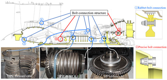
Figure 1. Typical aeroengine bolt connection structure distribution and location diagram.
The bolt connection structure of an aeroengine is fastened by a bolt array containing many bolts (about 32~60 for rotors and 60~140 for casings). The loading of the bolt preload is the key point of fastening. In the process of aeroengine bolt connection, the bolt preload cannot be directly controlled. Generally, through a certain tightening method, the tightening equipment is used to control the tightening torque, tightening angle, and other tightening process parameters to achieve the loading of the bolt preload indirectly. This loading method provides insufficient control over the bolt preload, which will cause the bolt preload to be inconsistent for the numerous bolts in the bolt array. In addition, part of the space of the bolt connection structure in aeroengines is small, and the use of general tightening equipment to tighten bolts in this structure will cause great difficulty in manual operation, seriously affecting the implementation accuracy of the tightening process and, ultimately, affecting the tightening quality of the bolts. Moreover, the bolts need to be disassembled repeatedly during trial assembly, test runs, and maintenance [2], greatly affecting the bolts’ tightening efficiency. The working environment of aeroengines is harsh, with the characteristics of high temperature, high pressure, and high speed. When the degree of control over the bolt preload is insufficient, it will directly affect the assembly quality of the bolted connection structure, including the degree of tightness between parts [3], structural deformation [4], contact stiffness [5], and nonlinear transmission characteristics [6], further affecting the sealing performance [7], friction and wear performance [8], stator clearance [9], stator support concentricity [10], connection stiffness (tension, compression, bending, and torsion stiffness) [11], rotor imbalance [12], and dynamic response characteristics [13] of parts under cyclic loads, which ultimately causes large vibration of the whole aeroengine [14] and affects the working life of the aeroengine in the harsh environment [15].
2. Bolt Preload Formation Mechanism
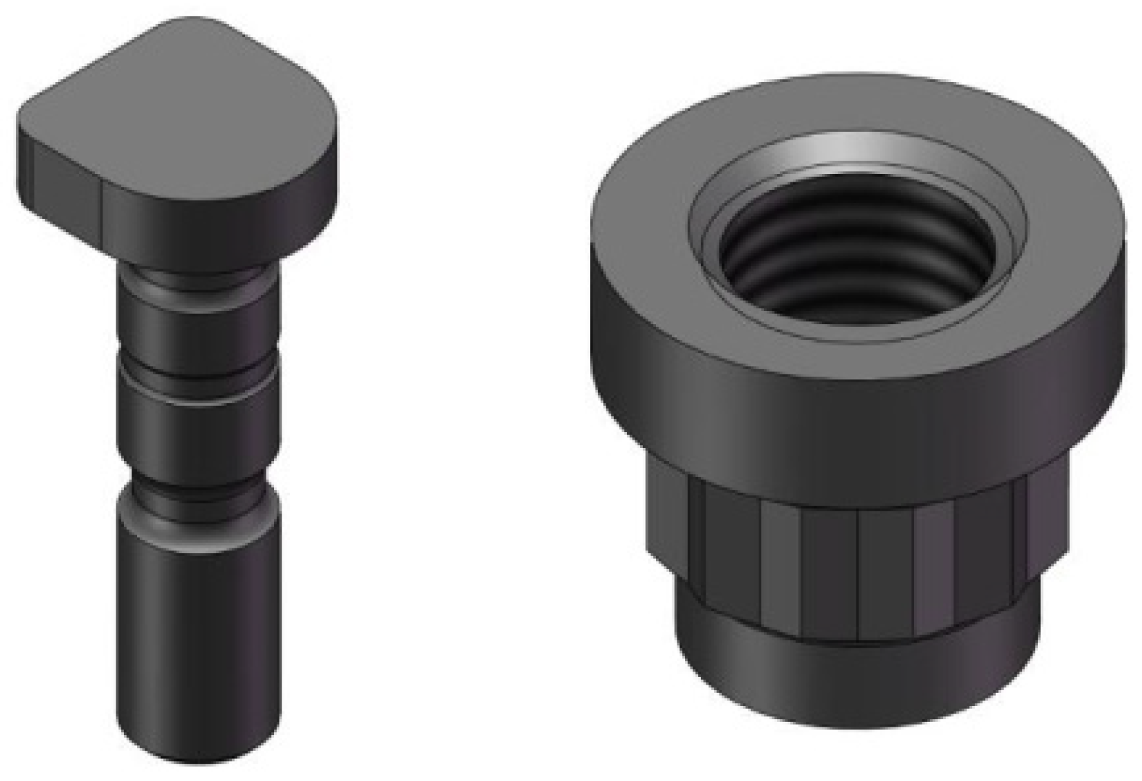
In order to adapt to the special working environment of the aeroengine, compared with ordinary bolts and nuts, the bolts and nuts commonly used in aeroengines have the following characteristics: In terms of materials, the material is a superalloy, which can maintain good mechanical properties at higher temperatures, bear large loads and high temperatures, and has the advantages of light weight, high strength, and corrosion resistance compared with ordinary bolts and nuts. In terms of structure, the most common bolts of aeroengines are D-type bolts, which are composed of a head, polished rod, and thread. The top view of the head resembles the capital letter D, so these are called D-type bolts [16]. The nuts most commonly used in aeroengines are self-locking nuts with good anti-loosening performance [17]. The bolts and nuts most commonly used in aeroengines are shown in Figure 2.
Figure 2. The bolt and nut types most commonly used in aeroengines [16].
In spite of the above characteristics, the tightening method of aeroengine bolts and nuts is the same as that of ordinary bolts and nuts. The torque is applied to the nuts by the tightening equipment to make the nuts rotate. The thread pairs between the bolts and nuts mesh, the bolts stretch under tension, and the compression deformation of the connected parts occurs under the pressure. The tensile force of the bolt is called the bolt preload, which is equal to the pressure of the connected parts, so as to compress the connected part and achieve the tightening effect. Therefore, the summary of the formation mechanism of the aeroengine bolt preload is mainly based on the current research on the formation mechanism of the common threaded connections. In addition, the research on self-locking nuts is also discussed.
As the preload is usually applied to each bolt in a certain sequence [18], the distribution of the preload of multiple bolts in the bolt array is mainly determined by the following two aspects: first, the torque is converted into the bolt preload for a single bolt; second, the tightened bolts affect the bolt preload of the untightened bolts.
2.1. Preload Formation Mechanism of a Single Bolt
According to the aviation industry standards [19][20], the relationship between the tightening torque M and the preload F of the common bolt can be expressed as follows:
where d is the nominal diameter of the thread, and K is the tightening torque coefficient of the bolt.
K is the correlation coefficient between the tightening torque and the preload when tightening the bolt, reflecting the efficiency of converting the tightening torque into an effective preload, and the magnitude and variation law of this coefficient provide important guidance for the design, manufacture, and installation of the bolt connection. Combined with the mechanical model of the bolt tightening process described by Motosh [21] and Gong et al. [22], the theoretical equation of the tightening moment coefficient of a common triangular thread bolt can be derived as follows:
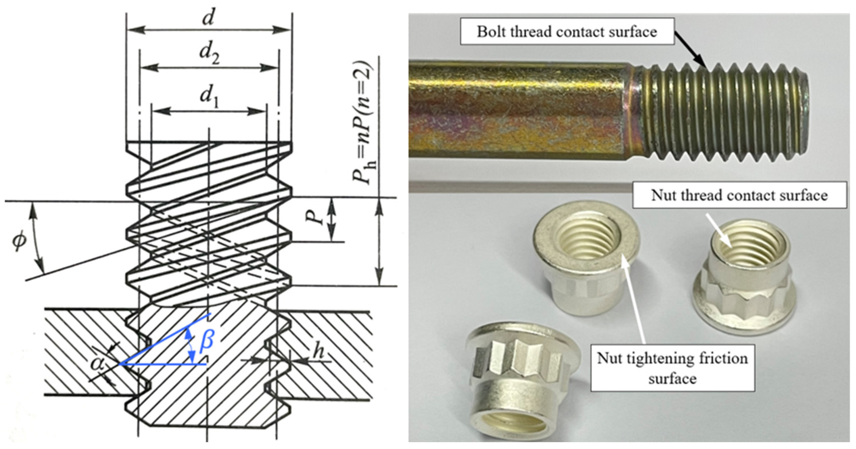
where P is the thread pitch, 𝜇t is the friction coefficient of the threaded substrate, 𝜇b is the friction coefficient of the nut support surface, 𝑟𝑡 is the effective friction radius of the threaded substrate, 𝑟b is the effective friction radius of the nut support surface, and 𝛽 is the thread profile’s half-angle.
The main geometric parameters of the thread and the name of each contact surface are shown in Figure 3. In practical applications, the effective friction radius of the threaded sub 𝑟t is generally expressed as an approximation of the average radius of the thread.
Figure 3. Main geometric parameters of the thread and contact surface position.
2.2. Preload Formation Mechanism of Multiple Bolts
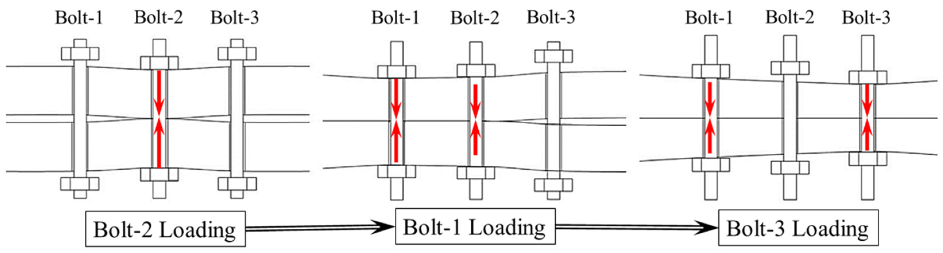
When a group of bolts are tightened in the same tightening process, each bolt can theoretically form the definite preload. However, in the single-axis tightening process, the preload of the first tightened bolt will change several times when the later bolts are tightened. This phenomenon is called bolt elastic interaction [23], as shown in Figure 4, and the intuitive reason is that the connected parts are deformed by the pressure of the tightening process.
Figure 4. Schematic diagram of bolt elastic interaction.
In 1992, Bibel et al. [24] proposed the elastic interaction coefficient matrix and established the mapping relationship between the relative positions of the bolts and the deformation distribution of the connected parts. They concluded that the tightening of bolts at neighboring positions decreased the bolt elongation, while the tightening of bolts at diagonal positions increased the bolt elongation, which caused the elastic interaction to gradually decrease with the increase in the preload.
3. Bolt Tightening Process
3.1. Bolt Tightening Process Parameters
Bolt tightening process parameters include the tightening sequence, tightening speed, tightening step, tightening times, lubrication conditions, and other aspects [25]. Among them, there are many kinds of bolt tightening sequences, including sequential tightening, cross-tightening, triangular tightening, symmetrical tightening, etc. How to choose an optimal sequence to complete the tightening of all bolts has been a key concern. The tightening steps refer to the number of steps used to tighten to the target torque. For example, if the bolt is tightened to the target torque in two steps, the tightening method is called “2 steps”. The torque of each step is called the step size. The tightening times refer to the number of instances of repeatedly tightening the bolts. The lubrication conditions refer to the conditions among the bolts, nuts, and connected parts. For these process parameters, many scholars have carried out research through theoretical analysis, simulation calculations, and experimental research, including research on individual process parameters and research on the coupling influence laws of several of them.
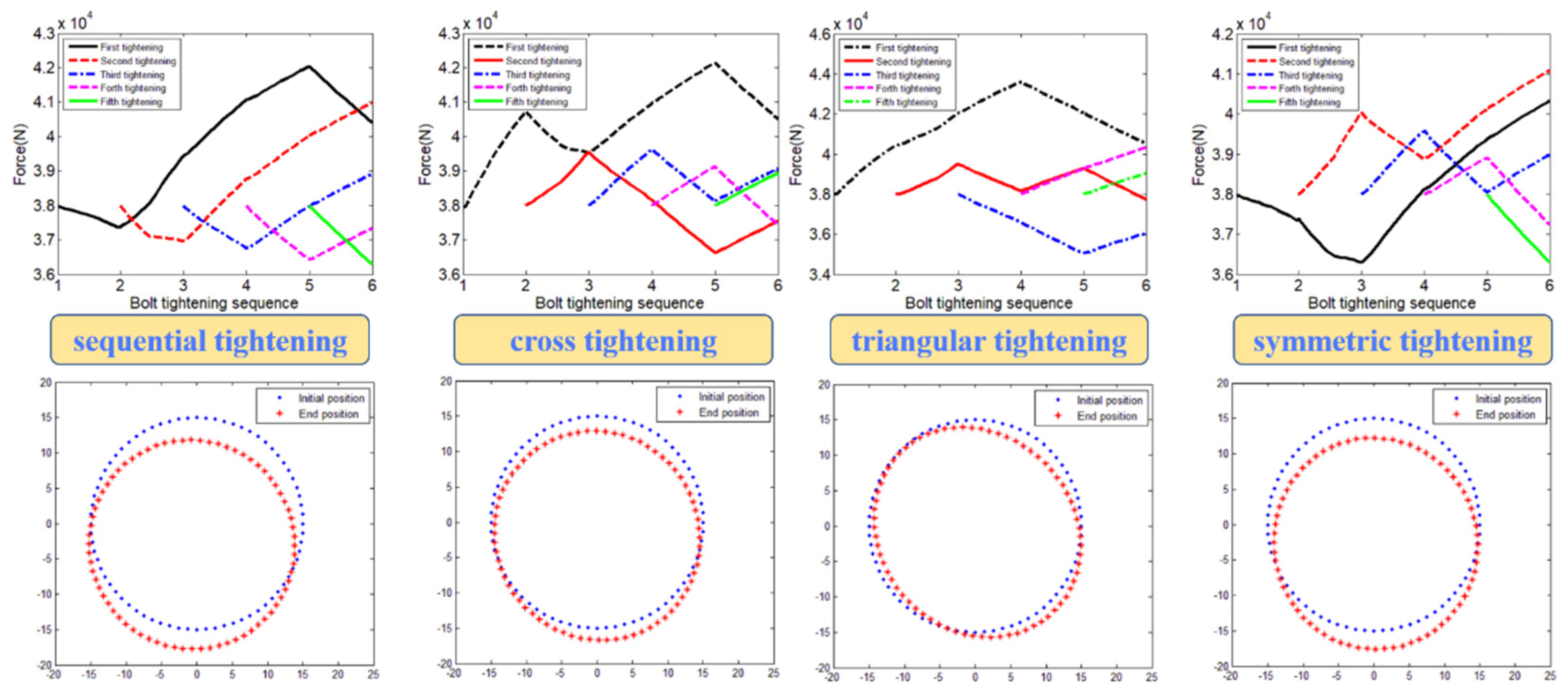
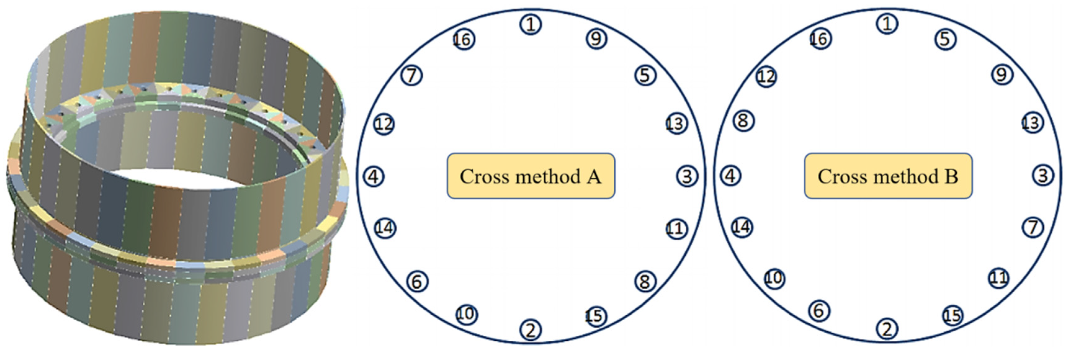
Hou [26] established a six-bolt finite element model of the flange bolt structure and studied the effects of four tightening sequences—sequential, cross-tightening, triangular tightening, and symmetric tightening—on the bolt connection quality (i.e., preload uniformity, form center, flange cylindricity, flange clearance). As shown in Figure 5, the standard deviation of the preload was the smallest under diagonal tightening; the flange cylindricity was the best under sequential tightening, but the form’s center position changed; the cylindricity and the position of the flange center were moderate under cross-tightening, and the flange gap mainly appeared in the inner ring of the flange, so the cross-tightening sequence was optimal. In addition, Chen [27] and Hao et al. [28] studied the optimization of the bolt tightening sequence by establishing finite element models for simulation analysis, in which Chen Shuang [29] established a 16-bolt finite element model of the rabbet bolt structure and studied the effects of the process combination of tightening sequence and tightening step on the bolt connection quality (i.e., preload uniformity, stop deformation, flange centering) to determine the optimal tightening sequence. It was found that the “2 steps” method was better than the “1 step” method, and the cross method B was better than the cross method A, as reflected in the smaller preload fluctuation and smaller deformation offset. Figure 6 shows the two methods.
Figure 5. Comparison of the effects of four tightening sequences on the change law of bolt preload and flange deformation [26].
Figure 6. Finite element model of 16 bolts and the sequence diagrams of cross-tightening methods A and B [29].
3.2. Bolt Tightening Method
The bolt tightening method is the loading method of the bolt preload. The different loading methods directly affect the magnitude of the bolt preload. According to the control degree of the preload during loading, the bolt tightening methods can be divided into three categories: open-loop control, semi-open-loop control, and closed-loop control. Among them, the torque method and torque angle method are common in open-loop control. The common methods in semi-closed-loop control include the pre-stretching control method and the yield point method, while the common methods in closed-loop control include the elongation detection method and the bolt loading method.
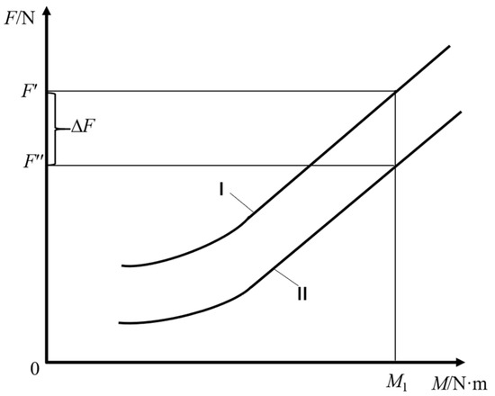
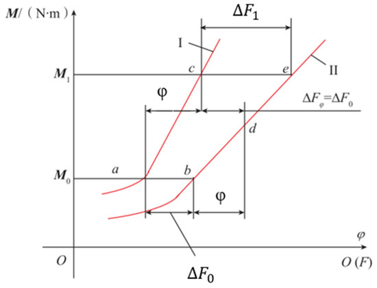
In the bolt tightening process, there is a certain loss when the tightening torque is transformed into preload, due to the influence of geometric size error between parts, shape error, surface roughness, and the physical properties of the workpiece [30]. The preload error obtained by the torque method is ±5%–±35%, and the worst will reach ±50%. The preload error of the torque method is the largest among all bolt tightening methods [31][32]. The schematic diagram of the preload error generated when tightening bolts via the torque method is shown in Figure 7. Combining the Taylor series expansion method and the Monte Carlo method, Toth [33] studied the control of bolt preload in the elastic and plastic zones by using the torque angle method of tightening, as shown in Figure 8. As this method can indirectly control the bolt elongation, the control accuracy of the bolt preload can be improved, and the preload error range can be controlled to ±15% [34].
Figure 7. Torque method for tightening bolts [35].
Figure 8. Torque corner method of tightening bolts [35].
4. Bolt Tightening Equipment
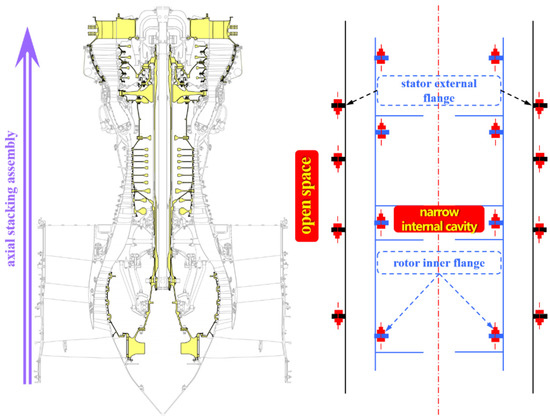
As shown in Figure 9, the assembly and connection of the stator system generally adopt the outward-flip flange bolt array, so the tightening equipment generally has an open tightening space, and the requirements for the tightening equipment are not high. In contrast, the assembly and connection of the rotor system generally adopt an inward-flip mounting edge flange bolt array. Due to the complex and compact structure of the rotor parts, it is easy to form a narrow internal cavity that is not directly visible. The requirements for the tightening equipment are high: firstly, it must not touch the aeroengine parts during the process of reaching the internal tightening position from the outside; secondly, the available operating space is extremely narrow and compact; and finally, the tightening process must be performed accurately. Therefore, the tightening equipment must be sufficiently automated and intelligent for such demanding tightening conditions. Based on the above, an overview of tightening equipment for aeroengines is presented below with respect to both open space and narrow space.
Figure 9. Schematic diagram of an aeroengine stator–rotor substructure system’s tightening space.
4.1. Open-Space Tightening Equipment
For bolt arrays in open space, due to the good visual conditions and spacious operation space, the tightening work is usually completed by manual use of tightening equipment or by automated tightening equipment. The following are the main kinds of manual tightening equipment: ordinary wrenches, bow wrenches, constant-torque wrenches, and electric wrenches.
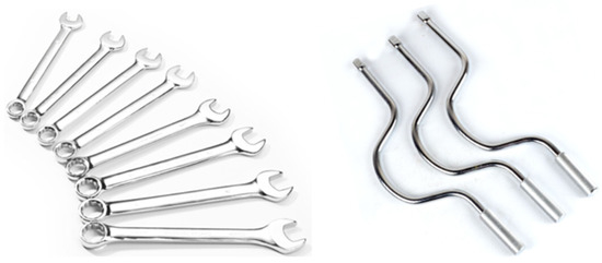
Ordinary wrenches, with their flexible design and simple structure, can fully meet the requirements of the axial and radial dimensions. However, they cannot achieve continuous tightening, and their efficiency is extremely low—not to mention their inability to accurately control the tightening torque. Therefore, ordinary wrenches are generally used in non-critical connection parts where the tightening torque is not required. The bow wrench is an improvement on the ordinary wrench, and it is generally oriented to the bolt connection parts with partially open vision but a compact radial dimension. It has the same problem as the ordinary wrench, in that it cannot achieve continuous tightening and accurately control the tightening torque. The physical diagrams of these two devices are shown in Figure 10.
Figure 10. Ordinary wrenches and bow wrenches.
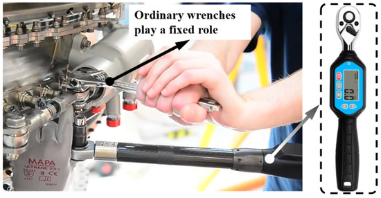
The constant-torque wrench can apply a specific torque value to the bolt and adjust the tightening torque. Some constant-torque ratchet wrenches can achieve continuous tightening, and this function is related to the structure of the tightening head. The tightening torque control accuracy of the constant-torque wrenches varies depending on the brand, and the tightening torque is applied manually, so the actual torque value applied to the bolt fluctuates greatly. Figure 11 shows a constant-torque wrench used in the assembly of an aeroengine [36][37].
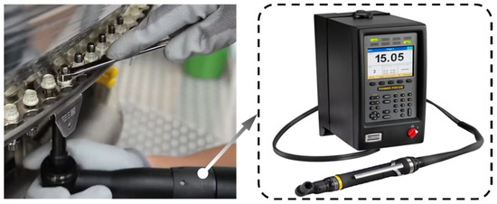
Electric wrenches apply accurate tightening torque to the bolts through the self-rotation of the tightening sleeve, and the user only needs to play the role of holding the electric wrench. The most widely used brands, such as Atlas Copco electric wrenches, have a tightening torque accuracy of ±3% or less. The rotation angle is monitored in real time, and the tightening speed is smooth and adjustable, so the electric wrenches can perform various tightening processes accurately and stably, and the quality consistency of their bolt connections is better, as shown in Figure 12.
Figure 12. Schematic diagram of an electric wrench.
4.2. Narrow-Space Tightening Equipment
For bolt connection arrays in narrow space, the tightening work is usually performed using special tightening equipment in this area, because it is not directly visible to the human eye. According to the degree of automation, the tightening equipment is mainly divided into manual tightening equipment and automatic tightening equipment. In addition, the degree of visualization of the tightening process (bolt tightening image visualization, real-time visualization of tightening parameters) is also considered.
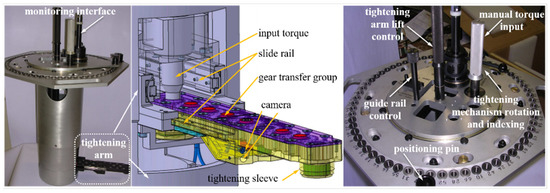
For the manual tightening equipment, the entire bolt tightening process is performed manually using the equipment, and the human work is the input of the tightening torque transmission chain, which can tighten the bolt array in the narrow operating space. However, the tightening torque control capability is poor, and the determination of the position of the bolts to be tightened mainly depends on the correspondence between the internal and external bolts (there is a certain phase relationship between the bolt array in the narrow space and the bolt array in the external open space, which can be used as a positioning reference from the outside), while the visualization degree is generally low, and the visualization function is mainly based on the image monitoring of bolt tightening. Italian Marposs [38] and China Aerospace Commercial Aero-engine Company [39][40] have developed corresponding equipment for the tightening of engine rotor bolts. Figure 13 shows the Marposs manual tightening equipment used for the rotor disk cavity of the high-pressure compressor.
Figure 13. Marposs visual manual tightening equipment [38].
Automatic tightening equipment means that after the equipment is manually installed to the engine, all of the tightening work is carried out by the equipment independently, and the electric wrench—as the input of the tightening torque transmission chain—can automatically ensure the stable output of the bolt tightening torque and rely on the bolt positioning module to determine the position of the bolt to be tightened. Its visualization degree is generally higher, and the visualization function is more suitable.
5. Conclusions
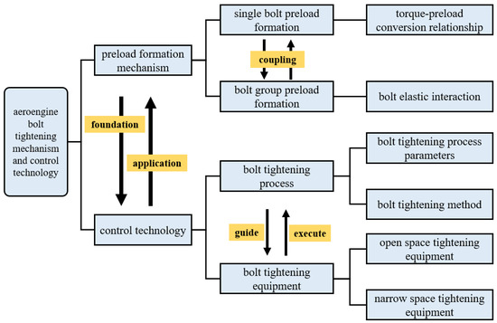
The control of the preload consistency of the aeroengine bolt array has always been a difficult problem in the aeroengine assembly process. The formation of the bolt preload includes two aspects: single bolts, and multiple bolts. Due to the existence of elastic interaction, the two will have coupling effects. The control of the bolt preload includes the bolt tightening process and bolt tightening equipment; the former guides the latter to implement bolt tightening, and the latter accurately implements the former. The relationship between the tightening mechanism and control technology is summarized in Figure 14. Among them, the formation mechanism of the bolt preload is the basis of the bolt preload control. The research of the formation of the bolt preload can provide theoretical guidance for the optimization of the bolt tightening process.
Figure 14. Diagram of the relationship between the bolt tightening mechanism and the control technology.
References
- Liu, Y.; Liang, C.; Shi, L. General Design of Aviation Gas Turbine; Science Press: Beijing, China, 2021.
- Yan, Q. Research on Assembly Tightness Detection Method for Aeroengine Bolt-Jointed Rotor; Chang’an University: Xi’an, China, 2019.
- Zhao, G.; Wang, Y.; Zhao, X.; Li, S.; Teng, G. Modeling and application test of contact stiffness of bolt connection structure of disk and drum. J. Aeronaut. Dyn. 2022, 37, 76–86.
- Jiao, J.; Mo, R.; Xu, G.; Fu, X.; Sun, H.; Chang, Z. Influence of position error of bolt hole on assembly mechanical characteristic of short precision bolted connection structure. J. Aeronaut. Dyn. 2021, 36, 935–947.
- Li, X.; Chen, G.; Yu, P.; Yang, M. Nonlinear stiffness mechanism analysis and numerical simulation of rabbet-bolted connection structure. J. Aeronaut. Dyn. 2021, 36, 358–368.
- Wang, K.; Yan, M.; Sun, Z.; Su, D.; Hui, A.; Liu, H. Influence factors of nonlinear stiffness of bolted flange connection structure under different loads. J. Aeronaut. Dyn. 2021, 36, 2503–2514.
- Ai, Y.; Lai, C.; Han, Y.; Sun, D.; Wu, L. Experiment on sealing characteristics of bolts flanged connections for aero-engines. J. Aeronaut. Dyn. 2018, 33, 2315–2323.
- Yu, P.; Zhao, Z.; Hou, L.; Chen, G. Analysis on analytical modelling and damping characteristics of bolted joint structure with spigot. J. Aeronaut. Dyn. 2021, 36, 2490–2502.
- Deng, W.; Mo, R.; Chen, K.; Feng, X.; Xia, H.; Sun, H.; Chang, Z. Prediction of rotor blade tip assembly clearance based on measured data for aero-engine. J. Aeronaut. Dyn. 2022, 37, 1273–1283.
- Bai, S.; Zhai, X.; AI, Y.; Ma, W. The influence of Bolted Connection on the Coaxial Tolerance and Dynamic Analysis in Aero-Engine Casing. J. Aeronaut. Dyn. 2010, 6, 35–37.
- Hong, J.; Xu, X.; Su, Z.; Ma, Y. Joint stiffness loss and vibration characteristics of high-speed rotor. J. Beihang Univ. 2019, 45, 18–25.
- Fan, Z. Study on the Influence of Bolt Preload on the Non-Continuous Rotor Dynamics of Aeroengine; Harbin Institute of Technology: Harbin, China, 2020.
- Sun, W.; Li, T.; Yang, D.; Sun, Q.; Huo, J. Dynamic investigation of aeroengine high pressure rotor system considering assembly characteristics of bolted joints. Eng. Fail. Anal. 2020, 112, 104510.
- Liu, Y.; Wang, D.; Hong, J.; Wu, F.; Jiang, G.; Huang, H. Analysis of Whole Aeroengine Vibration Control Technology. Aircr. Engine 2013, 39, 1–8+13.
- Sun, S.; Li, Y. Research on the Influence of Manufacturing Error of Aeroengine Rotor Installation Edge on Assembly Performance. Mod. Manuf. Technol. Equip. 2020, 56, 126–131.
- Zhang, B. Study on Loosening Regular Pattern of Bolt Connection of Low Pressure Turbine Shaft and Disc; Dalian University of Technology: Dalian, China, 2019.
- Zhang, X. Experimental Research on Evolution Law of Aero-Engine Bolt Connection Loosening Characteristics; Dalian University of Technology: Dalian, China, 2021.
- Zhang, B. Research on Precise Control of Pre Preload of Shaft Disk Connection of Low Pressure Turbine of Aero Engine; Dalian University of Technology: Dalian, China, 2018.
- HB/Z 251-1993; Relationship between Tightening Torque and Axial Force of Bolted Connections. China National Aviation Industry Corporation: Beijing, China, 1994.
- GB/T 16823.3-2010; Fasteners Torque-Clamp Force Testing. Standards Press of China: Beijing, China, 2011.
- Motosh, N. Development of Design Charts for Bolts Preloaded up to the Plastic Range. J. Eng. Ind. 1976, 98, 849–851.
- Gong, H.; Liu, J.; Ding, X. Calculation of the effective bearing contact radius for precision tightening of bolted joints. Adv. Mech. Eng. 2016, 8, 1–8.
- Bibel, G. Experimental and analytical study of elastic interaction in a pipe flange. In Proceedings of the International Conference on Pressure Vessel Technology, Dusseldorf, Germany, 31 May–5 June 1992.
- Bibel, G.; Ezell, R. An Improved Flange Bolt-Up Procedure Using Experimentally Determined Elastic Interaction Coefficients. J. Press. Vessel Technol. 1992, 114, 439–443.
- Ibrahim, R.; Pettit, C. Uncertainties and dynamics problems of bolted joints and other fasteners. J. Sound Vib. 2005, 279, 857–936.
- Hou, B. Mechanical Properties of Bolted Connection Structure under Real Contact Surface Topography; Dalian University of Technology: Dalian, China, 2020.
- Chen, C.; Yang, G.; Chang, D.; Hong, J. Assembly Connection Design Orienting to Sealing Performance of Joint Surface. J. Xi’an Jiaotong Univ. 2012, 46, 75–83.
- Hao, K.; Chen, Z.; Zhang, S.; Liang, Q.; Jiang, E.; Wang, R. Research on the Tightening Order of Multiple bolts for Cylindrical Parts. Mech. Res. Appl. 2016, 29, 20–21+25.
- Chen, S. Research on the Influence of Manufacturing Error of Mounting Edge of Bolts-Stop Connection on the Assembly Performance; Dalian University of Technology: Dalian, China, 2021.
- Bickford, J. Introduction to the Design and Behavior of Bolted Joints 4/e; CRC Press: Boca Raton, FL, USA, 2007.
- Defeo, J.; Juran, J. Juran’s Quality Handbook: The Complete Guide to Performance Excellence 6/e; McGraw Hill Professional: New York, NY, USA, 2010.
- Persson, E.; Roloff, A. Ultrasonic tightening control of a screw joint: A comparison of the clamp force accuracy from different tightening methods. Proc. Inst. Mech. Eng. Part C J. Mech. Eng. Sci. 2015, 230, 1989–1996.
- Toth, G. Torque and angle controlled tightening over the yield point of a screw-based on Monte-Carlo simulations. J. Mech. Des. 2004, 126, 729–736.
- Chu, T. Bolt Tightening Methods and Preload Control. Chem. Equip. Pipeline 2005, 42, 40–42.
- Sun, G.; Zhao, Z.; Yang, F.; Li, H. Application Experiment of “Torque–Angle” Method for Engine Disk and Shaft Connection. Aeronaut. Manuf. Technol. 2019, 62, 76–79+93.
- BiliBili Bullet Screen Video Network. Rolls-RoyceSuper Efficient Trent XWB Assembly Process of Series Turbofan Engine. 2018. Available online: https://www.bilibili.com/video/BV16s411J7ux/ (accessed on 27 March 2022).
- BiliBili Bullet Screen Video Network. The Whole Process of ej200 Engine Assembly. 2018. Available online: https://www.bilibili.com/video/BV1Wt411y7MF/ (accessed on 27 March 2022).
- MARPOSS. Aerospace Industry-MRO and Frock-Marposs. 2014. Available online: https://www.marposs.com/chi/application/aerospace-industry-mro-and-tooling (accessed on 28 March 2022).
- Li, L.; Zhang, Y.; Zhou, S.; Wang, X.; Chen, J.; Xiang, H.; Chen, D.; Wang, P. A Nut Placing and Tightening Device, Method and System. CN105522537B, 17 May 2017.
- Chen, D.; Wang, J.; Lin, L.; Zhang, Y.; Zhang, X.; Ouyang, K.; Ren, J. Nut Tightening Device. CN108237393B, 27 August 2019.
More
Information
Subjects:
Engineering, Aerospace
Contributors
MDPI registered users' name will be linked to their SciProfiles pages. To register with us, please refer to https://encyclopedia.pub/register
:
View Times:
1.7K
Revisions:
2 times
(View History)
Update Date:
20 Jul 2023
Table of Contents


Notice
You are not a member of the advisory board for this topic. If you want to update advisory board member profile, please contact office@encyclopedia.pub.
OK
Confirm
Only members of the Encyclopedia advisory board for this topic are allowed to note entries. Would you like to become an advisory board member of the Encyclopedia?
Yes
No
${ textCharacter }/${ maxCharacter }
Submit
Cancel
Back
Comments
${ item }
|
${ item.createdUser.fullName }
${ item.createdAt }
${ item.vote }
${ item.reply }
Delete
${ reply.createdUser.fullName }
${ reply.createdAt }
${ reply.vote }
Delete
There is no reply to this comment~
${ item.replyTextCharacter }/${ item.replyMaxCharacter }
Submit
Cancel
More
No more~
There is no comment~
${ textCharacter }/${ maxCharacter }
Submit
Cancel
${ selectedItem.replyTextCharacter }/${ selectedItem.replyMaxCharacter }
Submit
Cancel
Confirm
Are you sure to Delete?
Yes
No