1. Introduction
Personal mobility plays a crucial role in human society, serving as a highly valued aspect that is essential for both the productive functioning of the economy and individuals’ ability to access necessary opportunities for personal growth. The technologies and systems enabling widespread personal mobility offer substantial benefits that should not be underestimated. However, as accessibility and the range of mobility options increase, concerns about the long-term sustainability of our transportation systems also arise.
Currently, many transportation modes possess a significant physical presence, consume substantial amounts of energy resources, and contribute significantly to anthropogenic greenhouse gas emissions as well as local air, noise, and water pollution. It is imperative to address these issues to foster a more sustainable and environmentally friendly approach to personal mobility.
Electrification of transportation systems has been recognized and considered the most promising solution for many issues caused by greenhouse gas emissions. Nowadays, transportation systems contribute more than 20% of the total greenhouse gas emissions worldwide, while in the EU they account for more than 25%
[1]. In addition to reducing greenhouse emissions, electrification of transportation systems can also lead to higher energy efficiency, less required maintenance of vehicles, and better acceleration, which are seen as important advantages of electric vehicles (EVs) when making purchase decisions. Furthermore, EVs have the capability to directly utilize energy derived from renewable sources. When EVs are connected to the power grid, their batteries can play a crucial role in stabilizing the grid by balancing supply and demand, thereby facilitating the seamless integration of renewable energy sources. In addition, the adoption of electricity as a means of transportation is expected to make a significant contribution to enhancing the security of the energy supply.
By utilizing electricity for transportation, EVs not only increase the energy efficiency of vehicles, but they also bring about a diversification of energy sources in the transport sector. This becomes particularly important due to the persistently unstable political situation in many countries that export oil and gas. Such instability is expected to lead to future fluctuations in oil prices. Therefore, the ability to rely on alternative energy sources for transportation, such as electricity, becomes crucial in mitigating the potential impacts of these oscillating oil prices.
On the other hand, the limited maximum driving range and long charging time compared to the fuel refilling time of a gasoline-powered internal combustion engine (ICE) are the main drawbacks of EVs, especially plug-in battery electric vehicles (BEVs).
To meet EU sustainable and smart mobility strategy targets of at least 30 million zero-emission vehicles in operation on European roads and 100 climate-neutral European cities by 2030
[2], it is anticipated that a significant improvement in battery performance is required with respect to increasing the driving range of BEVs and the rate at which they can be recharged, along with the requirement that the cost of the purchase and ownership of BEVs must be comparable with the cost of internal combustion engine vehicles (ICEV). The industry is making significant progress in addressing the last requirement. Tesla has already cut BEV costs by 50% when comparing the flagship Model S and Model X to the newer Model 3 and Model Y. They announced that with the upcoming next-generation BEV platform, the costs will be further reduced. While the recent advances in battery production and their cost drops have led to the usage of battery packs of larger capacity, enabling improvements in the driving range of BEVs based on a single recharge, fast charging remains a major challenge
[3].
A comparison between different light-duty passengers’ BEVs and ICEVs in terms of the required travel times for an 845 km inter-city distance is presented in
[4]. The required travel time concerning the battery capacity heavily depends on the BEV’s maximum driving range, influencing the number of recharging stops and the time needed to recharge the battery. It is demonstrated that chargers of more than 400 kW are needed to have comparable travel times between EVs and ICEVs based on the current capacities of batteries. As a possible solution to this issue, the use of extremely fast chargers (XFCs) is proposed in
[5][6].
Recently, many leading car manufacturers have started BEV production with higher DC links in traction drives or have announced this transition very shortly. For some commercial upper-class passengers’ BEVs on the market and announced new releases, the data given in
Table 1 and
Table 2 were obtained from the Electric Vehicles Database
[7], which among many open-access databases on EVs offers the most comprehensive and up-to-date overview of all current and past electric vehicles. While
Table 1 summarizes data on the DC voltage system, nominal and usable (value is given in parentheses) battery capacity, and production year,
Table 2 summarizes data on the estimated efficiency, fast charge speed, and maximum fast charge power, along with the estimated average charge power over the 10% to 80% range of battery state-of-charge (SoC) for some commercial upper-class passengers’ BEVs (in parentheses). It is important to note that the car’s manufacturers provide fast charge speeds in terms of kilometers per minute (km/min) rather than kilowatts per minute because it gives drivers a more intuitive understanding of how fast the charging is, and additionally, it allows more accurate comparisons between different charging systems and vehicles. Fast charging speed is strongly connected with the average fast charge power, estimated efficiency, and battery capacity.
Table 2. Estimated efficiency, fast charge speed, and maximum fast charge power for some BEVs on the market and announced new releases.
| Vehicle |
Estimated Efficiency (Wh/km) |
Fast Charge Speed (km/min) |
Max. and Average Fast Charge Powers (kW DC) |
| Mercedes EQS 450+ |
170 |
15.8 |
207 (173) |
| NIO ET5 |
180 |
8.7 |
140 (100) |
| Tesla S Dual Motor |
165 |
13.2 |
250 (140) |
| Porsche Taycan 4S Plus |
182 |
18.8 |
268 (216) |
| Audi e-tron GT RS |
210 |
16.7 |
268 (216) |
| KIA EV6 Long Range |
180 |
17.8 |
233 (200) |
| Hyundai IONIQ 6 LR AWD |
149 |
19.2 |
233 (200) |
| Genesis GV60 Premium |
190 |
17 |
233 (200) |
| BYD HAN |
178 |
7.5 |
120 (85) |
| Lucid Air Pure |
157 |
16.3 |
200 (160) |
| XPENG G9 AWD |
214 |
15.3 |
300 (210) |
As seen from
Table 1, several manufacturers are migrating from current 400 V-based systems to ones with an 800-V rating. In addition to improving charging performance and efficiency, higher voltage systems allow battery recharge to be completed in a much shorter time, meaning that significantly lower charging currents can be utilized, resulting in less heat generation and possibly reduced energy loss. Consequently, more usable energy can be retained, and the vehicle travel range between charges will be significantly extended. Regardless of whether lower currents result in lower conduction losses, the total efficiency is not necessarily reduced because higher voltages cause higher switching losses when the same inverter technology is employed
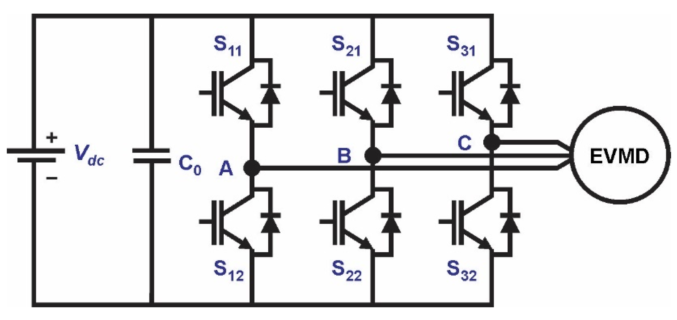
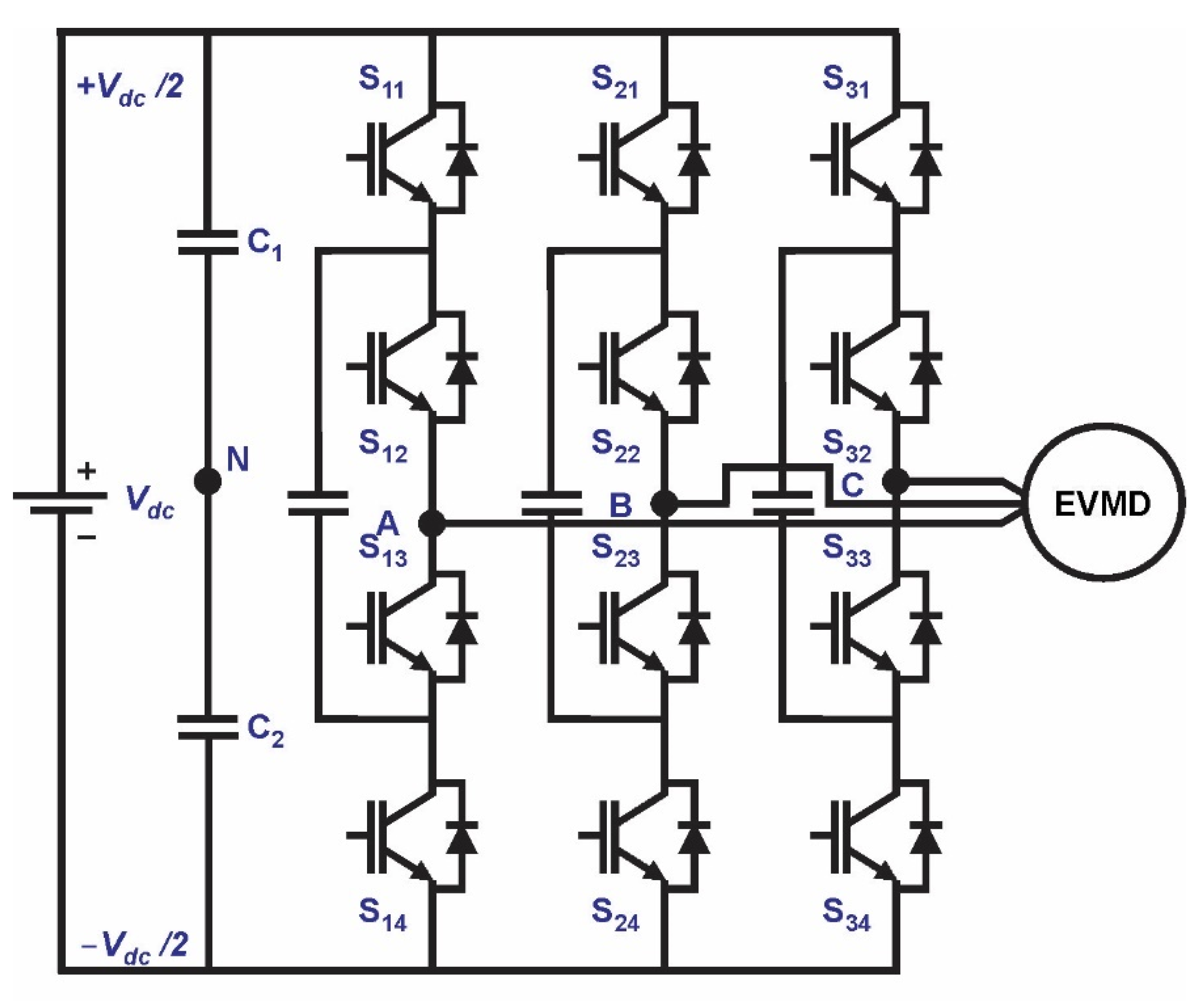
[8]. Due to the 650-V switch blocking voltage limitation, a conventional 3-phase six-switches 2-level inverter, shown in
Figure 1, is unsuitable for applications with an 800-V DC link voltage. Therefore, either the semiconductors or the inverter topology must be changed. High-voltage semiconductor production involves higher costs, and their usage results in higher switching losses. Therefore, using a multilevel inverter (MLI) appears to be a more promising and possible solution.
Figure 1. Conventional 2-level, 3-phase VSI topology for electric vehicle motor drive.
2. Multilevel Inverters
MLIs are undoubtedly state-of-the-art in applications with high power and high voltages (e.g., electric power plants) or in applications that require good-quality sinusoidal currents (e.g., photovoltaic inverters)
[9]. With the trend of higher voltages and power demand in automotive electric drivetrains, the advantages of MLI, such as higher efficiency, higher power density, better waveform quality, lower switching frequency, the possibility of using low-rated switches, and inherent fault tolerance, become valuable for automotive main traction drives. The significant demand for power components that comes with the electrification of the automotive industry will continue to grow for the next few decades. Parallelly, the efficiency of battery energy usage is critical for the cost and performance of electric cars, and wide bandgap (WBG) Gallium-Nitride (GaN)-based components, which are superior to competing technologies, are undermining the long reign of silicon in the power world.
The fundamental operational principle of MLI involves generating a stepped output voltage waveform that approximates a sine shape, enabling higher voltage and power levels to be achieved. The MLI’s structure typically comprises one or more DC sources and an array of low-rate power semiconductor switches. By increasing the number of voltage levels in the output waveform and employing an appropriate switching strategy, it becomes possible to generate an almost sinusoidal output voltage without the need for bulky transformers and passive filters. Regarding their structure, conventional MLIs can generally be categorized into three main types: neutral point clamped (NPC), flying capacitor-based (FC), and cascade H-bridge (CHB). Their basic, well-established topologies have been extensively analyzed
[10][11][12][13] and documented, and they have been commercially used for more than two decades.
Speaking of MLI, more sinusoidal currents (lower total harmonic distortion (THD)) reduce harmonic losses in the electric motor, support the noise, vibration, and harshness (NVH) characteristics of the electric drivetrain, improve the EMC behavior, and therefore also reduce the stimulation of bearing currents. The lower THD is achieved by utilizing additional voltage levels in the output voltage of the MLI when compared to the standard 2-level type inverter. However, despite the numerous advantages of MLIs, they also come with certain drawbacks. These include the requirement for voltage balancing, a higher number of semiconductor switches and capacitors, and a more complex control system.
2.1. Cascade H-Bridge MLI
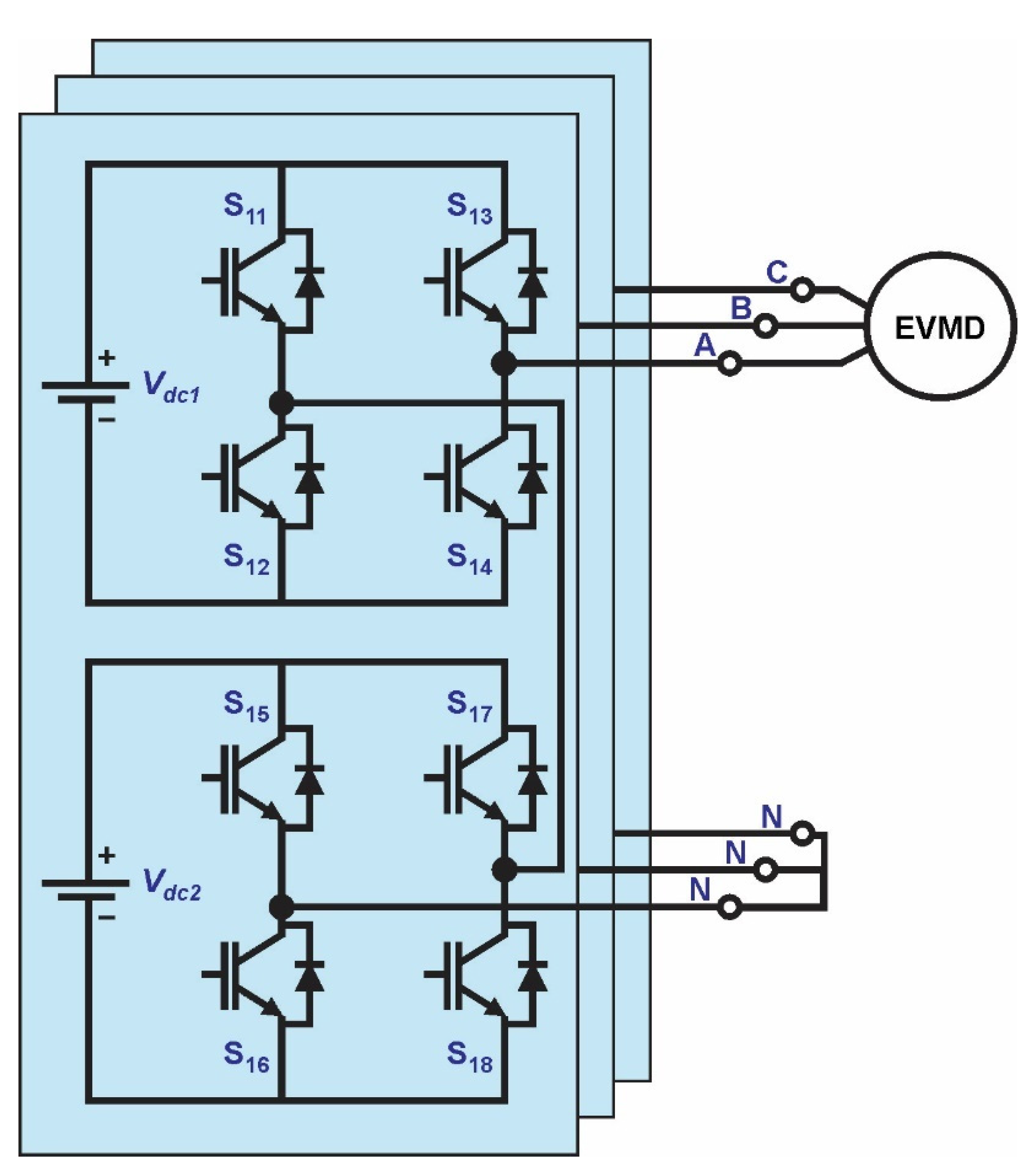
The concept of MLI technology appeared in the 1970s with the introduction of the multilevel stepped waveform generated with a series-connected H-bridge, which is also known as a cascaded H-Bridge converter (CHB). In the last two decades, several companies have commercialized it, and it is suitable for FACTS and motor drive applications. The topology of a 3-phase, 5-level CHB is shown in Figure 2.
Figure 2. Topology of a 3-phase, 5-level CHB MLI.
The main features of CHB topology are its modular structure realized by simple power cell (H-bridges) serial connection, allowing fault-tolerant operation with added bypass switches, and straightforward extension by using a large number of series connecting cells, resulting in a large number of levels in the generated high nominal output voltage. Generally, when n H-bridges are serially connected, the 2 × n + 1 voltage levels are obtained in the inverter output voltage at the lowest component count when compared to FC and NPC MLI topologies. Equalization of losses, equal power distribution, and improved quality of the output voltage waveform can be achieved by applying a well-known phase-shifted pulse-width modulation (PWM) technique. Since each H-bridge requires an independent DC source, this can be seen as the main topology drawback, limiting its suitability for some applications. For proper comparison of MLI inverter topologies, the allowed switching states and output voltage levels for 3-level CHB MLI are given in Table 3.
Since output voltage zero level can be generated by connecting the inverter output either to the positive or negative inverter bars, this redundancy can be exploited to enable fault-tolerant operation. When more H-bridges are serially connected, the redundancy inherently increases as each H-bridge has one redundant switching state.
2.2. NPC MLI
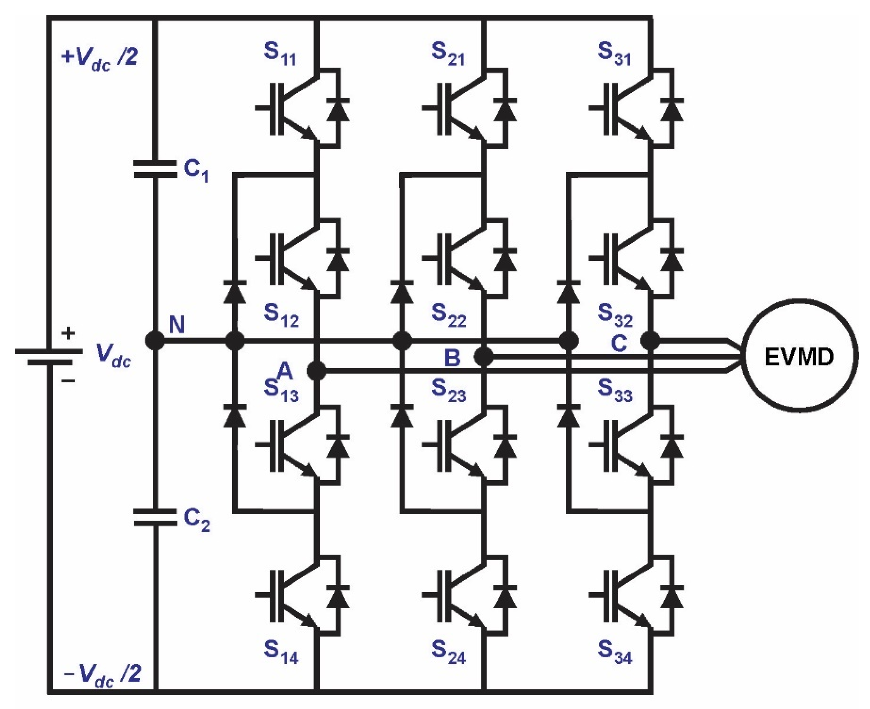
Eventually, in the late 1970s, the concept of the diode-clamped converter (DCC) emerged. Over time, it transformed into the three-level Neutral Point Clamped (3-level NPC MLI) inverter that we are familiar with today. A 3-phase, 3-level NPC, shown in
Figure 3, was first proposed in
[14]. The presented results of an analytical and experimental comparison between an NPC PWM-based MLI and a conventional 2-level inverter confirm its excellent drive system efficiency and suitability for a wide-range variable speed operation. Since then, it has been the topic of numerous research projects in academia and industry, to name a few
[15][16][17][18].
Figure 3. Topology of a 3-phase, 3-level NPC MLI.
This topology consists of three legs, where in each inverter leg, two conventional 2-level inverters with the midpoint of the transistors connected to neutral point N by two clamping diodes enable the generation of an additional zero voltage level in the inverter output voltage. Taking first-leg operation as an example, the allowed switching states and corresponding output voltage levels are given in Table 4.
Table 4. A 3-level NPC MLI allows switching states and output voltage levels.
| Switching States |
S11 |
S12 |
S13 |
S14 |
Output Voltage |
| 1 |
1 |
1 |
0 |
0 |
Vdc/2 |
| 2 |
0 |
1 |
1 |
0 |
0 |
| 3 |
0 |
0 |
1 |
1 |
−Vdc/2 |
As each semiconductor device must block just half of the inverter input DC voltage, switches with lower voltage ratings can be adopted, or when the same switches are used, the inverter power rating can be doubled with respect to 2-level inverters.
This development marked the introduction of a multilevel power converter specifically designed for medium-voltage applications. For more than two decades, many companies have successfully commercialized this technology, primarily for medium-voltage applications, such as Flexible AC Transmission Systems (FACTS) and motor drives. The key advantage of the 3-level NPC inverter lies in its topology, where clamping diodes are incorporated to equalize the blocking voltages across the semiconductor power switches. By employing a simple PWM level-shifted multicarrier modulation strategy with added zero-sequence injection, DC voltage imbalance control can be achieved.
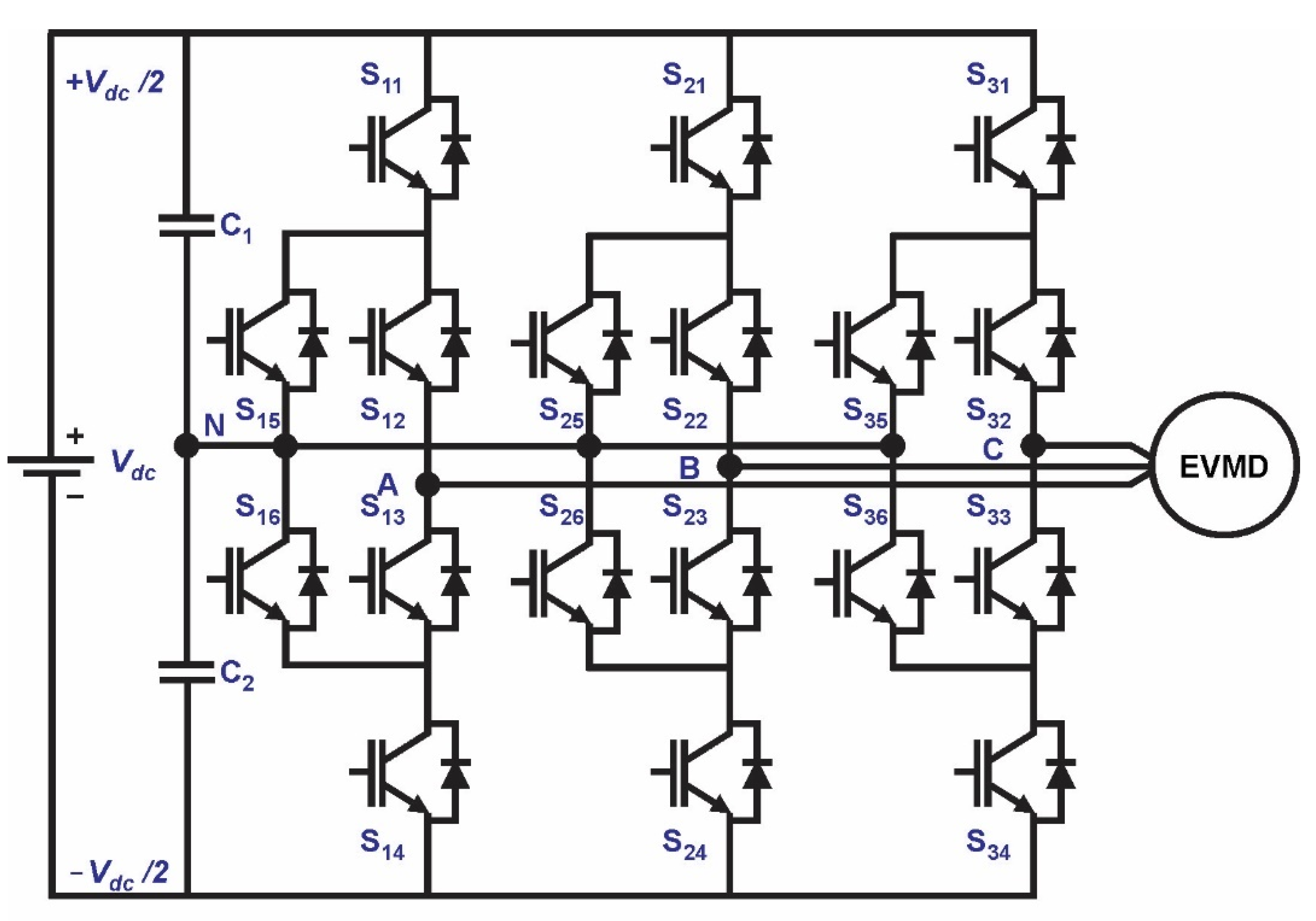
The main NPC MLI disadvantage appears to be an unequal distribution of the losses between semiconductor switches, leading to unequal temperature distribution and setting limits on inverter output power. To overcome this drawback, the active NPC MLI topology shown in
Figure 4 has been proposed. In this topology, the clamping diodes are replaced by active semiconductor switches, allowing the application of an appropriate modulation strategy to assure evenly distributed power loss between semiconductor switches, subsequently improving the inverter terminal characteristics
[19][20][21][22][23]. The distribution of power loss can be controlled only during the output zero-voltage level, as this can be achieved in four different switching states.
Figure 4. Topology of a 3-phase, 3-level active NPC MLI.
2.3. Flying Capacitor MLI
CHB and NPC technologies were closely followed by the development of a FC low-power topology that is primarily used in medium-voltage FACTS and motor drive applications, especially in traction drives. The FC MLI topology is like the NPC topology, where the clamping diodes are simply replaced by flying capacitors, as can be seen in Figure 5.
Figure 5. Topology of a 3-phase, 3-level FC MLI.
In this inverter topology, the zero-voltage level cannot be generated directly by connecting the load to the neutral point, but it is achieved by connecting the load through the flying capacitor with DC-link opposite polarity to the positive or negative bar. In FC topology, the four switching states seen in Table 5 are allowed, and two of them generate zero voltage levels. This redundancy can be exploited for power loss optimization.
Table 5. A 3-level FC MLI allows switching states and output voltage levels.
| Switching States |
S11 |
S12 |
S13 |
S14 |
Output Voltage |
| 1 |
1 |
1 |
0 |
0 |
Vdc/2 |
| 2 |
1 |
0 |
1 |
0 |
0 |
| 3 |
0 |
1 |
1 |
0 |
0 |
| 4 |
0 |
0 |
1 |
1 |
−Vdc/2 |
3.4. MLIs: Design and Power Loss Considerations
MLI topologies have now become regarded as classic or traditional MLI configurations that have been successfully implemented as industrial products over the past two decades. Multiple manufacturers in the field have commercialized these inverters, offering varying power ratings, front-end configurations, cooling systems, semiconductor devices, control schemes, and other technical specifications. Among these, the 3-level NPC and CHB MLIs have gained the most popularity in industrial applications.
As already stated, the MLIs offer desirable characteristics for medium- to high-voltage, high-power applications. However, they have more complex topologies than traditional 2-level inverters, and their operation is not straightforward, involving problems to be solved. From Table 6, where the formulas to calculate the number of components for all three MLI topologies for m-level output voltage generation are given, it can be concluded that all topologies rely on the same number of semiconductor switches. The number of diodes significantly increases with the number of levels (m) in the output voltage in NPC MLI, limiting its industrial usage to 3-level topologies due to the complex mechanical arrangement of non-symmetrical power switches. Similarly, the number of flying capacitors increases in FC MLI topology, and due to their bulkiness, the inverter dimensions also significantly increase, making them less suitable for BEV applications.
Table 6. Component numbers in classical MLI topologies for m-level output voltage.
| Topology |
No. of DC Voltage Sources Vdc |
No. of Switches |
No. of Capacitors |
No. of
Diodes |
Max. and Min. Output Voltages |
| NPC MLI |
1 |
2(m − 1) |
(m − 1) |
(m − 1)(m − 2) |
+Vdc/2, −Vdc/2 |
| FC MLI |
1 |
2(m − 1) |
(m − 1) +
(m − 1)(m − 2)/2 |
0 |
+Vdc/2, −Vdc/2 |
| CHB MLI |
(m − 1)/2 |
2(m − 1) |
0 |
0 |
+((m − 1)/2)Vdc,
−((m − 1)/2)Vdc |
In
[24], a comprehensive overview of classical and advanced reduced switch MLI topologies, along with different control schemes and their various power system applications, is presented, indicating that many features of the recently developed switch reduced MLI topologies, such as cost effectiveness, reduced volume, and ease of control, make them superior over classical MLI topologies. Unfortunately, the overview does not cover the application of MLI in BEVs, where efficiency and reliability are the most important features. This topic is addressed in
[11], where a multilevel cascade inverter has been proposed to be used in variable types of heavy-duty EVs such as BEVs and hybrid electric vehicles (HEVs), and in
[25], where a comprehensive review of power electronics technologies in EVs with a focus on inverter topologies for electric traction drives is presented. A comprehensive review focused on reduced-switch MLI for EV applications is discussed in
[26]. The comparative analysis of different latest topologies based on component count, efficiency, and THD of the inverter’s output voltage shows that the highest working efficiency of 99.4% is achieved with 3-level active NPC MLI and the lowest THD of 1.6% with interleaved 9-level FC MLI in high power applications.
Recently, many authors proposed and analyzed the working principle of reduced-component MLI topologies with voltage boosting capability up to twice the voltage gain originally intended for transformer-less grid-connected PV applications
[27][28][29]. As they exhibit inherent capacitor voltage self-balancing, no additional balancing circuit is needed, resulting in a compact, high-power density structure, which makes them good candidates for low DC-link voltage BEV applications.
In any battery-supplied power system, operation efficiency is of primary concern, so loss analysis is important when deciding on inverter topology. Semiconductor component power losses can be divided into three categories: conduction losses, switching losses, and blocking losses (normally neglected), which can be either analytically calculated for specific MLI topologies or estimated by simulations. As conduction losses appear on semiconductor components during conduction state, they depend on inverters’ operational point correlated current and on state component resistances, so in principle, inverter topologies with fewer semiconductor components operate with fewer conduction losses when the same type of switch is applied. Switching losses are wasted power dissipated during switching on and off the semiconductor switch, occurring also on antiparallel diodes, so they are highly correlated to the switching frequency and depend on the standing voltage of the switches and the adopted modulation strategy. Power loss evaluation in MLI topologies is a highly demanding task, as the current through each power switch can differ, resulting in a different on-state ratio. Additionally, the power switches can work with different switching frequencies. On-line model-based calculation of power losses in 7-level CHB MLI with IGBT switches is presented in
[30].
Even though MLI topologies consist of more components than conventional 2-level inverters, their efficiency is higher because they use lower-rated switches with lower on-state resistance, especially when operating at a higher switching frequency.
 +1 credit