Your browser does not fully support modern features. Please upgrade for a smoother experience.
Submitted Successfully!
 +1 credit
Thank you for your contribution! You can also upload a video entry or images related to this topic.
For video creation, please contact our Academic Video Service.
| Version | Summary | Created by | Modification | Content Size | Created at | Operation |
|---|---|---|---|---|---|---|
| 1 | Wenceslao Eduardo Rodríguez-Rodríguez | -- | 1947 | 2023-07-06 18:16:53 | | | |
| 2 | Camila Xu | Meta information modification | 1947 | 2023-07-07 03:05:43 | | |
Video Upload Options
We provide professional Academic Video Service to translate complex research into visually appealing presentations. Would you like to try it?
Cite
If you have any further questions, please contact Encyclopedia Editorial Office.
Rodríguez-Rodríguez, W.E.; Puente-Sujo, J.A.; Rodríguez-Rodríguez, A.J.; Matias, I.R.; Vargas-Requena, D.T.; García-Garza, L.A. Theoretical Background of SMS Sensors. Encyclopedia. Available online: https://encyclopedia.pub/entry/46536 (accessed on 24 June 2026).
Rodríguez-Rodríguez WE, Puente-Sujo JA, Rodríguez-Rodríguez AJ, Matias IR, Vargas-Requena DT, García-Garza LA. Theoretical Background of SMS Sensors. Encyclopedia. Available at: https://encyclopedia.pub/entry/46536. Accessed June 24, 2026.
Rodríguez-Rodríguez, Wenceslao Eduardo, Jesús Abraham Puente-Sujo, Adolfo Josué Rodríguez-Rodríguez, Ignacio R. Matias, David Tomás Vargas-Requena, Luis Antonio García-Garza. "Theoretical Background of SMS Sensors" Encyclopedia, https://encyclopedia.pub/entry/46536 (accessed June 24, 2026).
Rodríguez-Rodríguez, W.E., Puente-Sujo, J.A., Rodríguez-Rodríguez, A.J., Matias, I.R., Vargas-Requena, D.T., & García-Garza, L.A. (2023, July 06). Theoretical Background of SMS Sensors. In Encyclopedia. https://encyclopedia.pub/entry/46536
Rodríguez-Rodríguez, Wenceslao Eduardo, et al. "Theoretical Background of SMS Sensors." Encyclopedia. Web. 06 July, 2023.
Copy Citation
SMS (single mode–multi mode–single mode) sensors' structures are constituted by splicing a multi-mode-no-core fiber (MMF-NC, also known as coreless)-defined segment to two single-mode fiber pigtails.
fiber optic sensors
SMS
etching
LabVIEW
computer vision
glucose
1. Introduction
In the last decades, fiber optic sensor (FOS) development has been growing by research centers, both private and public, owing to their capabilities including small dimensions, multiplexing capability, performance at hazardous conditions and long distances, and immunity to electromagnetic interferences [1]. Therefore, they are preferred in front of other technologies. Due to their optical and physical properties, they have been applied to measure parameters such as refractive index, temperature, strain, pressure, and stress [2][3][4]. Moreover, their implementation for monitoring chemical and biological variables by the deposition of sensitive coatings to a specific analyte is possible [5][6][7]. In FOS, the electromagnetic field that travels through the waveguide in a specific fiber section interacts with the interest surrounding medium, allowing spectral response modulation as the monitoring mechanism. This energy portion is known as the Evanescent Wave (EW) [8]. Its study attracts great interest because it depends on the fiber sensor sensitivity. This means that the longer the EW distance of the fiber that interacts with the interest medium, the higher the sensitivity will be, i.e., the stronger the interaction with the study analyte [9]. The strategy to follow involves modifying the fiber geometry through the sensing section diameter reduction. This can be allowed by the following techniques: heat pulling or etching [10].
The heat-pulling method consists in generating a huge amount of heat either by a flame, electric arc, or a power laser applied to the fiber. At the same moment, both waveguide tails are fixed on translation stages; these axially pull the structure, thus reducing a section and lead to diminishing the core and cladding dimensions at the same proportion, and the developed fiber geometry consists in a taper waist [10][11]. A main drawback to consider in this method is that the fiber tends to break during the process [12]. The etching method comprises a process realized by a chemical reaction via a corrosive agent based on a liquid or vapor, focused an ion beam or dry reactive ion. Liquid etching (also called wet etching) provides a low-cost, feasible, and effective strategy in comparison to heat pulling and the other etchant methods due to the high cost of the experimental equipment needed. Wet etching occurs by fiber immersion into a corrosive solution, which is typically Hydrofluoric Acid (HF).
The state-of-the-art provides knowledge-focused strategies on the etching process in distinct FOS, to reach different sensing applications. Inside the contributions published in this area, there are certain variables to consider, and there are laboratory recommendations for carrying out the experiments, such as room and acid temperature, relative humidity, HF concentration (which leads to a diameter rate variation), fixing the fiber to maintain the structure straight to avoid any bending, and utilizing a container to keep the acid.
The first strategy exposed involves diminishing the diameter sensing region via fiber immersion in HF during a certain duration. S.K Al-Hayali et al. realized etching experimentation with SMS (single mode–multi mode–single mode) sensors for temperature monitoring (coated with a sensitive thin layer fabricated by Copper Oxide/Polyvinyl Alcohol). The structure was diminished until 18 μm using a U-groove to contain the HF at a 40% concentration, obtaining a rate of ~2.84 μm/min [13]. Following the SMS structures, two other contributions have been made. W. E. Rodríguez-Rodríguez et al. reported pH sensor development (coated with a sensitive thin layer constituted by Poly Allylamine Hydrochloride/Poly Acrylic Acid) applying an etch bath based on HF at 40%, keeping the fiber straight using a U-holder manufacturing three different structures with distinct diameters: 64.15 μm, 41.07 μm, and 23.73 μm. They reported that their technique to measure the fiber diameters after the corrosive task was via a computational algorithm based on image triangulation [14]. A. J. Rodríguez-Rodríguez et al. exposed an SMS sensor applied to the gasohol quality control; the structure was fixed onto a channel engraved in a Delrin plate manufacturing the diameter through a buffered corrosive solution, which is a mixture of ammonium fluoride and HF (6:1 volume ratio). The etch task was realized over a 130 min130 min period of reducing the fiber diameter to ~90 μm [15]. M. A. Riza et al. applied an etch bath to FBG (Fiber Bragg Gratings) structures, this being mandatory to its performance as a humidity sensor. Note that these sensors are not sensitive to the surrounding mediums due to the light transmission being confined to the fiber core. So, partial or total remotion of the cladding is necessary. The mentioned contribution reports the utilization of an ABS (Acrylonitrile Butadiene Styrene) holder (manufactured by 3D printing) to straighten the fiber, and an acrylic case to contain the HF at 48%, reaching a diameter of ~10 μm, and etching rate of ~~1.69 μm/min [16]. P. Zaca-Morán et al. realized tests in SMF (single-mode fibers) as a sucrose concentration sensor using HF at 48~51%, diminishing the structure until reaching 7.3 μm by a rate of 3.27 μm/min [17]. Following from the previous sensor structure, P. S. Sharma et al. proposed a glucose concentration sensor requiring HF at 40%, containing the acid with a PVC dish. The main contribution of this research has been the demonstration of the temperature, and magnetic stirring effects during the etching, proving that, at higher temperature and stirring speed, the corrosion rate increases [18]. The main drawback of the previous contributions is the absence of some monitoring technique, technology, or parameter that ensures the current measurement diameter during and after the corrosion. To address this issue, a state-of-the-art method presents a second strategy based on online spectral response monitoring which allows to predict the structure diameter. These are mentioned in the next paragraph.
H. J. Kbashi et al. presented an etching process based on two stages: the first one using HF at 30% to remove the cladding, and the second one by HF at 24% to reduce the core diameter, obtaining rates of 1.284 μm/min and 0.184 μm/min, respectively. The experiments were carried out at room temperature [9]. S. Azad et al. showed etching experimentation with MMF (multi-mode fiber) structures applied to humidity sense (coated with a sensitive thin layer fabricated by Zinc Oxide) using HF diluted at a 25% concentration to remove the cladding, obtaining a rate of 0.75 μm/min, and HF at 40% to reduce the core diameter until 28 μm reaching a rate of 1.115 μm/min [19]. In both of the previous contributions, the acid was contained by a Teflon dish and the optical power output monitoring as a fiber diameter measurement mechanism for use during the corrosive task was realized. Following certain fiber structure fabrication characteristics (physical, optical, and geometrical), it is possible to tune the spectral response via the real-time monitoring through the diameter chemical corrosion process. Del Villar et al. demonstrated in LPFG (Long-Period Fiber Gratings) sensors that it is possible to adjust a certain LP (Linearly Polarized) mode appreciated in the spectral response as a dual attenuation band during the etching process, following the Dispersion Turning Point phenomenon, through a specific grating period. The experimentation exposed presents an implementation as a pH sensor (coated with a sensitive thin layer constituted by Poly Allylamine Hydrochloride/Poly Acrylic Acid), allowing to attain a fiber diameter adjustment of up to ~25 μm [20]. Additionally, W.E. Rodríguez-Rodríguez et al. proved that is possible to adjust the SMS sensor diameter through the fourth self-image band presence during the online etch monitoring, defining the sensitive section length according to certain parameters established by the Multi-Modal Interference phenomenon [21]. The experimentation reported an application as an automotive antifreeze sensor, permitting to fabricate three sensors with different diameters. In both of these previous contributions, a U-holder was employed to maintain the fiber as straight along with a PLA (Polylactic Acid) cuvette (fabricated by 3D printing) to maintain the acid.
It is important to mention that in some of the previous contributions the researchers have corroborated the fiber diameter measures through conventional digital microscopes [13][14][16][18][20][21]. This represents a low cost way to measure the fiber diameter. However, other exposed contributions have realized the diameter measurement through SEM (Scanning Electron Microscopy) [9][17][19]. Unfortunately, this last technology represents an economic drawback due its high cost [22]. Therefore, to obtain a specific diameter adjustment in the FOS is fundamental in the implementation of a measurement system in real time during the etching process, to track the process of supervising for which no failure occurs such as evaporation acid, movements or bending in the fibers. A vision measurement system would contribute to monitoring, and avoid the mentioned issues, allowing the researchers its resolution; moreover, it would permit to measure the fiber diameters during the corrosive bath until reaching the desired adjustment.
2. Theoretical Background of SMS Sensors
SMS structures are constituted by splicing a multi-mode-no-core fiber (MMF-NC, also known as coreless)-defined segment to two single-mode fiber pigtails. In this kind of fiber sensor, the light that travels through the SMF core is coupled to several propagation modes in the no-core fiber, and thus, a light interaction with the surrounding medium occurs. The previous phenomenon leads to the modulation of its spectral response. The MMF-NC modes have different effective refractive indexes; so, the phase of these modes is distinct when the light is coupled to the core mode of the output SMF segment; causing a constructive and destructive interference as a wavelength function. At the coreless region, it is possible to find light input self-images at specific distances [23][24]. This phenomenon is known as Multi-Modal Interference [25]. The equation that describes the MMF-NC segment (L) where these images appear is defined by the following expression.
where 𝑝 is the order of the self-image, 𝑛𝑛𝑐 is the effective refractive index, 𝐷 is the MMF-NC diameter, and 𝜆 is the vacuum’s wavelength. Most of the literature has focused on the fourth-order self-image, that has proved that it possesses a narrow band-pass filter spectral response. Like other fiber sensor configurations, the SMS accomplishes its operation due to the light absorption carried by the EW in the MMF-NC region, allowing the interaction with the surrounding refractive index (SRI), depicted in Figure 1.
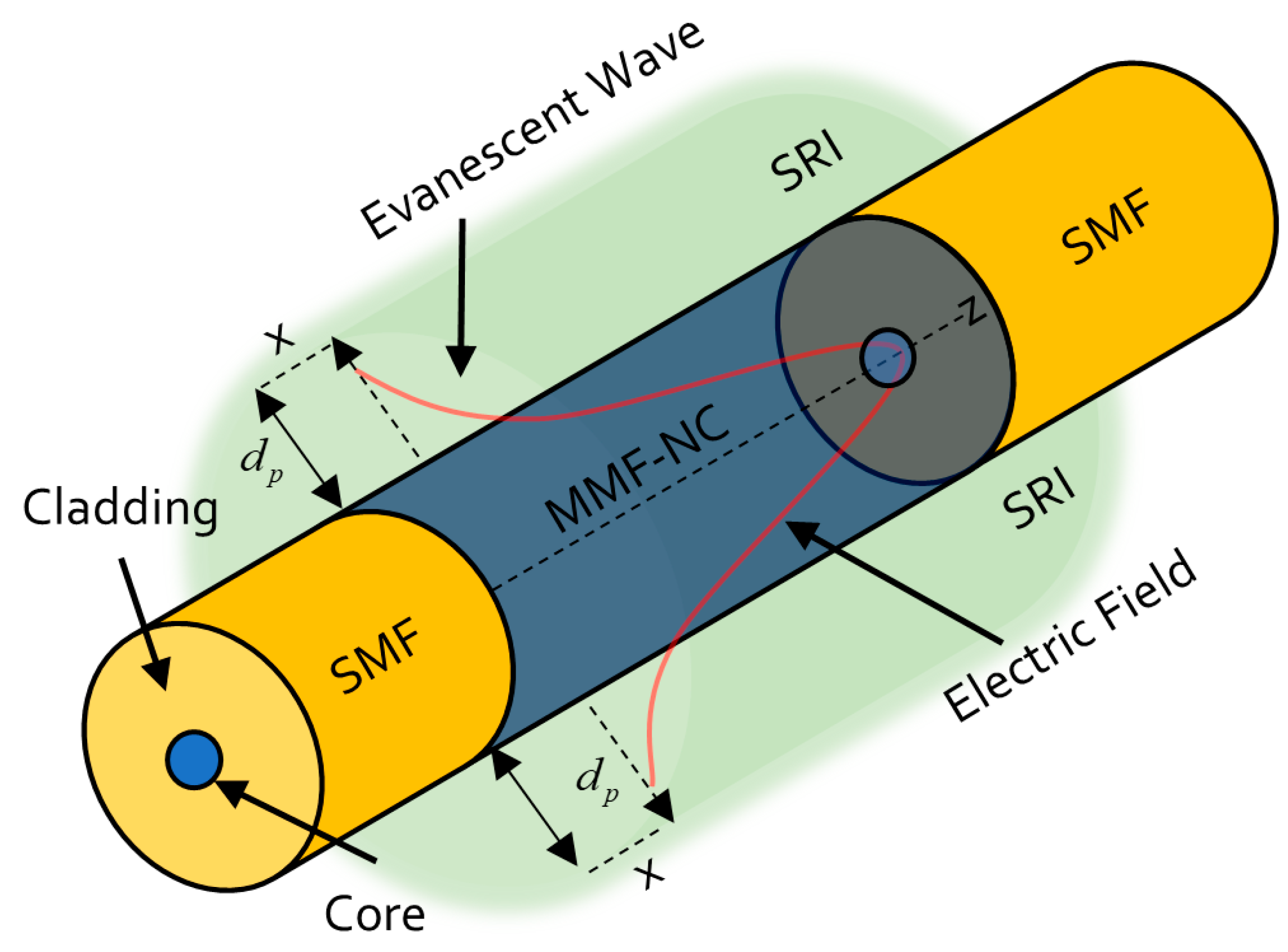
Figure 1. Evanescent wave phenomenon in SMS sensors.
The EW is the optical wave that decays exponentially in the perpendicular direction to the MMF-NC/SRI interface. For sensing applications, it is relevant to consider the penetration dept 𝐷𝑝 of the evanescent wave; here, the distance from the mentioned interface where the electric field amplitude decreases by , defined by
where 𝜃𝑖 is the incident angle in the MMF-NC/SRI interface, and 𝑛𝑆𝑅𝐼 is the surrounding refractive index. So, a relationship between 𝐷𝑝 and SRI exists. Therefore, the previous deduction allows to deduce that to enhance the SMS sensor sensitivity is necessary to increase the 𝐷𝑝 evanescent wave intensity. This can be reached by the MMF-NC diameter diminution. The HF application as a corrosive agent makes the mentioned reduction possible. Once this happens, the etching in the fiber when it is lower in diameter is in the sensitive region, and when higher, it will be the interaction between the interfered high-order modes and the SRI, leading to a higher sensitivity in SMS devices [26]. In addition to the previous SMS sensitivity enhancement background theory, there are two other aspects to consider. The first one is, as the longer the fourth self-image wavelength is established, the higher the sensor sensitivity will be. The second one is that when the SMS sensors operate at an SRI near to the 𝑛𝑁𝐶, it will reach the higher sensitivity, considering the fact that the SRI cannot be higher than the 𝑛𝑁𝐶 in the sensors’ implementation. In the case of the present research, 𝑛𝑁𝐶=1.4525, and an operation wavelength at 800 nm is considered.
References
- Budd, E.; Spillman, W.B. Fiber Optic Sensors: An Introduction of Engineers and Scientists, 2nd ed.; Wiley: Hoboken, NJ, USA, 2011.
- Zhao, Y.; Cai, L.; Hu, H.F. Fiber-optic Refractive index sensor based on multi-tapered SMS fiber structure. IEEE Sens. J. 2015, 15, 6348–6353.
- Tafulo, P.A.R.; Jorge, P.A.S.; Santos, J.L.; Araujo, F.M.; Frazao, O. Intrinsic Fabry–Pérot cavity sensor based on etched multimode graded index fiber for strain and temperature measurement. IEEE Sens. J. 2012, 12, 8–12.
- May-Arrioja, D.A.; Ruiz-Perez, V.I.; Bustos Terrones, Y.; Basurto-Pensado, M.A. Fiber optic pressure sensor using a conformal polymer on multimode interference device. IEEE Sens. J. 2016, 16, 1956–1961.
- Wang, X.D.; Wolfbeis, O.S. Fiber-optic chemical sensors and biosensors (2008–2012). Anal. Chem. 2012, 85, 487–508.
- Wang, X.D.; Wolfbeis, O.S. Fiber-optic chemical sensors and biosensors (2015–2019). Anal. Chem. 2019, 92, 397–430.
- Corres, J.M.; Matias, I.R.; Del Villar, I.; Arregui, F.J. Design of pH sensors in long-period fiber gratings using polymeric nanocoatings. IEEE Sens. J. 2007, 7, 455–463.
- Sharma, A.K.; Gupta, J.; Sharma, I. Fiber optic evanescent wave absorption-based sensors: A detailed review of advancements in the last decade (2077-19)”. Optik 2019, 183, 1008–1025.
- Kbashi, H.J. Fabrication of submicron-diameter and taper fibers using chemical etching. J. Mater. Sci. Technol. 2012, 28, 308–312.
- Korposh, S.; James, S.W.; Lee, S.W.; Tatam, R.P. Tapered optical fibre sensors: Current trends and future perspectives. Sensors 2019, 19, 2294.
- Kaur, M.; Hoert, G.; Lane, P.M.; Menon, C. Fabrication of stepped optical fiber tip for miniaturized scanners. Opt. Fiber Technol. 2021, 61, 102436.
- Merchant, D.F.; Scully, P.J.; Schmitt, N.F. Chemical tapering of polymer optical fiber. Sens. Actuators A Phys. 1999, 76, 365–371.
- Al-Hayali, S.K.; Al-Janabi, A.H. All fiber-optic temperature sensor based on cladding etched no-core fiber coated with nanostructured copper oxide-polyvinyl alcohol thin film. Sens. Actuators A Phys. 2020, 220, 165154.
- Rodríguez-Rodríguez, W.E.; Del Villar, I.; Zamarreño, C.R.; Matias, I.R.; Arregui, F.J.; Rodríguez-Rodríguez, A.J.; Domínguez-Cruz, R.F. Sensitivity enhancement experimental demonstration using a low cutoff wavelength SMS modified structure coated with a pH sensitive film. Sens. Actuators B Chem. 2018, 262, 696–702.
- Rodríguez-Rodríguez, A.J.; Baldovino-Pantaleón, O.; Domínguez-Cruz, R.F.; Zamarreño, C.R.; Matias, I.R.; May-Arrioja, D.A. Gasohol Quality Control for Real Time Applications by Means of a Multimode Interference Fiber Sensor. Sensors 2014, 14, 17817–17828.
- Riza, M.A.; Go, Y.; Maier, R.J. Dynamics rate of fiber chemical etching: New partial removal of cladding technique for humidity sensing application. Laser Phys. 2020, 30, 126205.
- Zaca-Moran, P.; Padilla-Martínez, J.P.; Perez-Corte, J.M.; Dávila-Pintle, J.A.; Ortega-Mendoza, J.G.; Morales, N. Etched optical fiber for measuring and refractive index of sucrose solutions by evanescent waves. Laser Phys. 2018, 28, 116002.
- Sharma, P.S.; Choudhary, K.; Gupta, V.K.; Kumar, S. Low-cost fabrication, and characterization process for development of a sensitive optical fiber structure. Appl. Opt. Eng. Lab. Notes 2022, 61, 8057–8063.
- Azad, S.; Sadeghi, E.; Parvizi, R.; Mazaheri, A.; Yousegi, M. Sensitivity optimization of ZnO clad-modified optical fiber humidity sensor by means of tuning the optical fiber waist diameter. Opt. Laser Technol. 2017, 30, 96–101.
- Del Villar, I.; Rodríguez, W.E.; Fuentes, O.; Socorro, A.B.; Diaz, S.; Corres, J.M.; James, S.W.; Tatam, R.P. Sensitivity Enhancement in Low Cutoff Wavelength Long-Period Fiber Gratings by Cladding Diameter Reduction. Sensors 2017, 17, 2094.
- Rodríguez-Rodríguez, W.E.; Rodríguez-Rodríguez, A.J.; Zamarreño, C.R.; Del Villar, I.; Zúñiga, M. Low Cutoff Wavelength Etched SMS Structures Towards Verification of the Quality of Automotive Antifreeze. IEEE Sens. J. 2020, 20, 11342–11349.
- Ziao, L.Z.; Dong, D.M.; Zheng, W.G.; Wu, W.B.; Shen, C.J.; Yan, H. Research on fiber-optic etching method for evanescent wave sensors. Optik 2013, 124, 740–743.
- Punjabi, N.; Satija, J. Mukherji, Evanescent Wave Absorption Based Fiber-Optic Sensor—Cascading of Bend and Tapered Geometry for Enhanced Sensitivity. In Sensing Technology: Current Status and Future Trends III Smart Sensors, Measurement and Instrumentation 11; Springer: Berlin/Heidelberg, Germany, 2015; pp. 25–45.
- Fukano, H.; Kushida, Y.; Taue, S. Multimode/interference/structure optical/fiber temperature sensor with high sensitivity. IEICE Electron. Express 2013, 18, 20130812.
- Soldano, L.B.; Pennings, E.C.M. Optical Multi-Mode Interference devices based on self-imaging: Principles and Applications. J. Light. Technol. 1995, 4, 615–627.
- Zhao, Y.; Cai, L.; Li, X.-G.; Meng, F.; Zhao, Z. Investigation of the high sensitivity RI sensor based on SMS fiber structure. Sens. Actuators A Phys. 2014, 205, 186–190.
More
Information
Subjects:
Instruments & Instrumentation
Contributors
MDPI registered users' name will be linked to their SciProfiles pages. To register with us, please refer to https://encyclopedia.pub/register
:
View Times:
989
Revisions:
2 times
(View History)
Update Date:
07 Jul 2023
Table of Contents


Notice
You are not a member of the advisory board for this topic. If you want to update advisory board member profile, please contact office@encyclopedia.pub.
OK
Confirm
Only members of the Encyclopedia advisory board for this topic are allowed to note entries. Would you like to become an advisory board member of the Encyclopedia?
Yes
No
${ textCharacter }/${ maxCharacter }
Submit
Cancel
Back
Comments
${ item }
|
${ item.createdUser.fullName }
${ item.createdAt }
${ item.vote }
${ item.reply }
Delete
${ reply.createdUser.fullName }
${ reply.createdAt }
${ reply.vote }
Delete
There is no reply to this comment~
${ item.replyTextCharacter }/${ item.replyMaxCharacter }
Submit
Cancel
More
No more~
There is no comment~
${ textCharacter }/${ maxCharacter }
Submit
Cancel
${ selectedItem.replyTextCharacter }/${ selectedItem.replyMaxCharacter }
Submit
Cancel
Confirm
Are you sure to Delete?
Yes
No