1. Tree-like Design
Three instances of tree-like topologies are going to be taken into account herein. The first design is a fat tree, whose main feature is the establishment of three layers of switches, where the lower one is called the edge layer (which is the one in touch with the nodes), the middle one is named the aggregation layer, and the upper one is branded the core layer
[1]. This design has strict specifications, such as it establishes a parameter
k that governs the number of hosts and switches in each layer as well as the ports linking different layers.
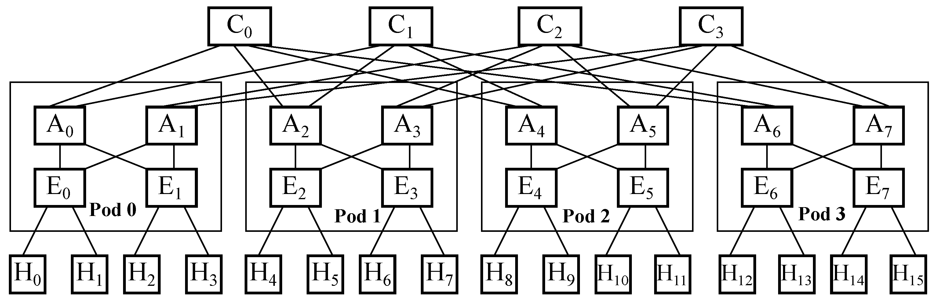
Figure 1 exhibits the devices in each layer in a fat tree topology where 𝑘=4 and the oversubscription rate is 1:1, meaning that no expected links are missing. In that picture, H represents the nodes (also called hosts), E represents the edge switches, A represents the aggregation ones, and C represents the core ones, where elements of the same kind are sequentially numerated from left to right. It is to be noted that a fat tree architecture organizes switches in the lower and middle layers in groups whereby full mesh connectivity among both layers within a single group is achieved. Those groups are called pods, and there is full mesh connectivity among them through the switches in the upper layer, although each individual switch in the middle layer just gets partial mesh connectivity with all upper-layer switches.
Figure 1. Devices in each layer in a fat tree topologywith 𝑘=4 and oversubscription rate 1:1.
The second design is leaf and spine, whose main characteristic is the establishment of two layers of switches, where the lower one is named the leaf and the upper one is called the spine
[2]. In this case, no parameter governs the number of devices or ports among layers, so there is some freedom of design when it comes to choosing the number of hosts and switches in each layer.
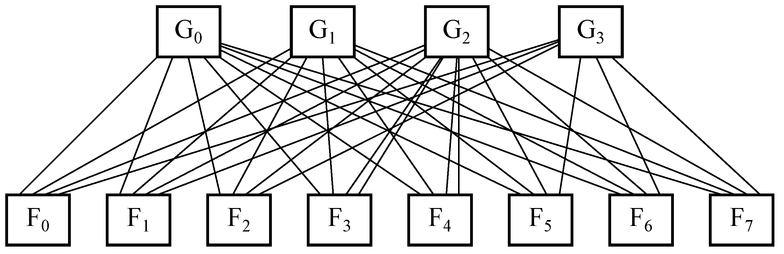
Figure 2 exposes the devices in each layer in a leaf and spine topology with eight leaf switches, these are represented by
F, and four spine switches, branded as
G, whilst the number of nodes per each leaf is not fixed. It is to be said that there is full mesh connectivity between switches located in both layers.
Figure 2. Devices in each layer in a leaf and spine topologywith 8 leaves and 4 spines.
The third design is hub and spoke, which may be considered atwo-level treestructure wherein the hub is on top of the hierarchy and the spokes are at the bottom
[3]. In many production environments, it is quite common to use a redundant hub and spoke design, where two hubs are used for redundancy purposes and a number of spokes are connected to each of them, and where network traffic may be load-balanced so as to try to leverage all links.
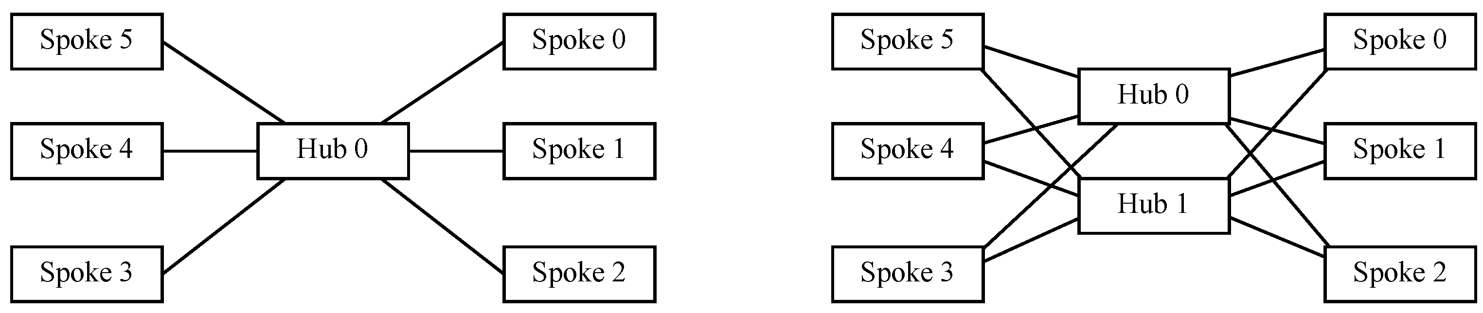
Figure 3 exhibits on the left-hand side the devices within each layer in a single hub and spoke topology with one switch acting as a hub and six nodes acting as spokes, whereas on the right-hand side, a redundant hub and spoke topology replicates the former scheme by adding another hub into the design for redundancy purposes. In both cases, all interspoke communications take place through a hub, so that every pair of spokes is just two hops away.
Figure 3. Devices in each layer in a redundant hub and spoke topologywith 6 spokes and a single hub (left) or a redundant hub (right).
2. Graph-like Design
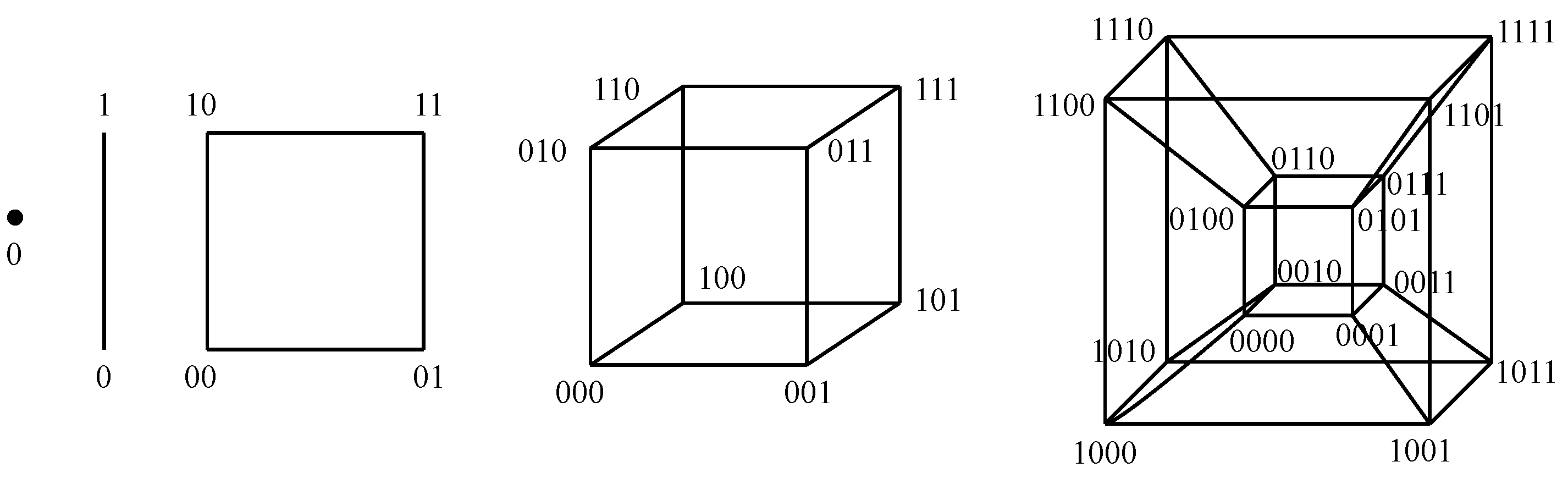
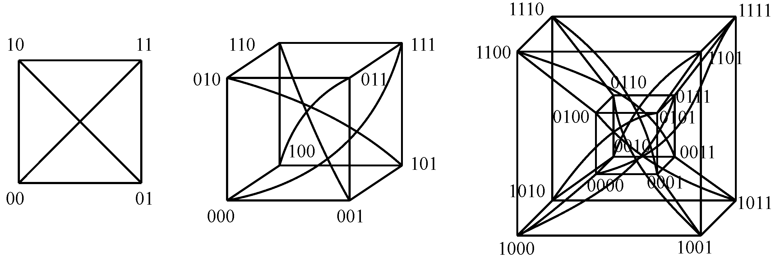
Some instances of graph-like designs are going to be considered herein. The first design is the N-hypercube, where two nodes share each available line in a given dimension. This way, each node has N links to its neighbors: just one per dimension. The overall number of nodes is 2𝑁, and the distance between opposite nodes is N. Figure 4 shows the nodes within N-hypercubes of lower dimensions.
Figure 4. Nodes in N-hypercubes of dimensions {0⋯4}{0⋯4} (from left to right).
The second design is a folded N-hypercube, where the previous topology is taken and, in turn, links between each pair of opposite nodes are added. That way, each node has 𝑁+1 links to its neighbors, and the distance between opposite nodes is just one. This implies that performance is improved although the design has become more complex. Figure 5 exposes the nodes within the folded N-hypercubes of lower dimensions.
Figure 5. Nodes in folded N-hypercubes of dimensions {2⋯4}{2⋯4} (from left to right).
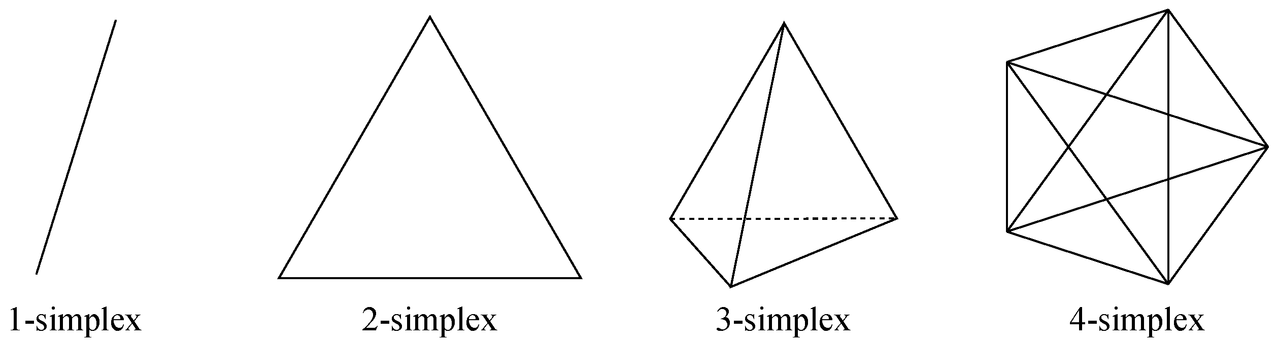
The third design is N-simplex, which is basically a full mesh topology, as all nodes are directly connected to each other. Hence, there are 𝑁+1 nodes, where each of them has N links to its neighbors, resulting in a distance of one between any pair of nodes. Figure 6 exhibits the nodes for the N-simplices of lower dimensions.
Figure 6. Nodes in N-simplices of dimensions {1⋯4}{1⋯4} (from left to right).
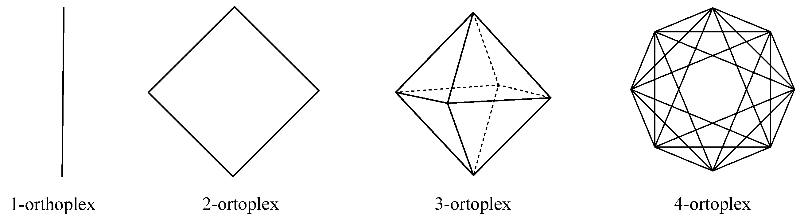
The fourth design is N-orthoplex, where the previous topology is taken and, in turn, links between each pair of opposite nodes are deleted, resulting in a quasi full mesh topology. Hence, there are 2𝑁 nodes, whereby each of them has 2(𝑁−1) links to its neighbors, resulting in a distance of one between any pair of nodes except for opposite nodes, for which the distance is two. Figure 7 depicts the nodes for the N-orthoplices of lower dimensions.
Figure 7. Nodes in N-orthoplices of dimensions {1⋯4}{1⋯4} (from left to right).
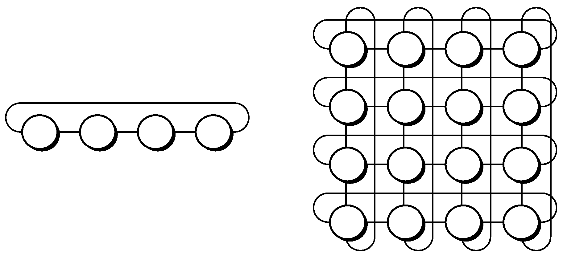
The fifth design is k-ary n-cube, also known as camcube, which is a toroidal topology. This is basically a grid where nodes at the edges of a certain line in a given dimension have a wraparound link, thus turning those into direct neighbors. The number of nodes is 𝑘𝑛, and each node has 2𝑛 links. Figure 8 exposes a couple of examples, where n accounts for the number of dimensions involved and k denotes the number of nodes within a given dimension. It is to be noted that if 𝑘=2, then the shape obtained is that of the N-hypercube.
Figure 8. Nodes in k-ary n-cube (left: 4-ary 1-cube; right: 4-ary 2-cube).
The sixth design is Hamming graph 𝐻(𝑛,𝑛−1), whose topology may be seen as a folded version of the k-ary n-cube because an extra link directly connects each pair of nodes that are at the maximum distance, which in the previous case was ⌊𝑘/2⌋ when 𝑛=1 and 2×⌊𝑘/2⌋ if 𝑛=2, whilst now it is half of those values, although complexity has grown in the design. Figure 9 exhibits an 𝐻(𝑛,𝑛−1) where 𝑛=2 and 𝑛=4.
Figure 9. Nodes in Hamming graph 𝐻(𝑛,𝑛−1) (left: 𝑛=2; right: 𝑛=4).
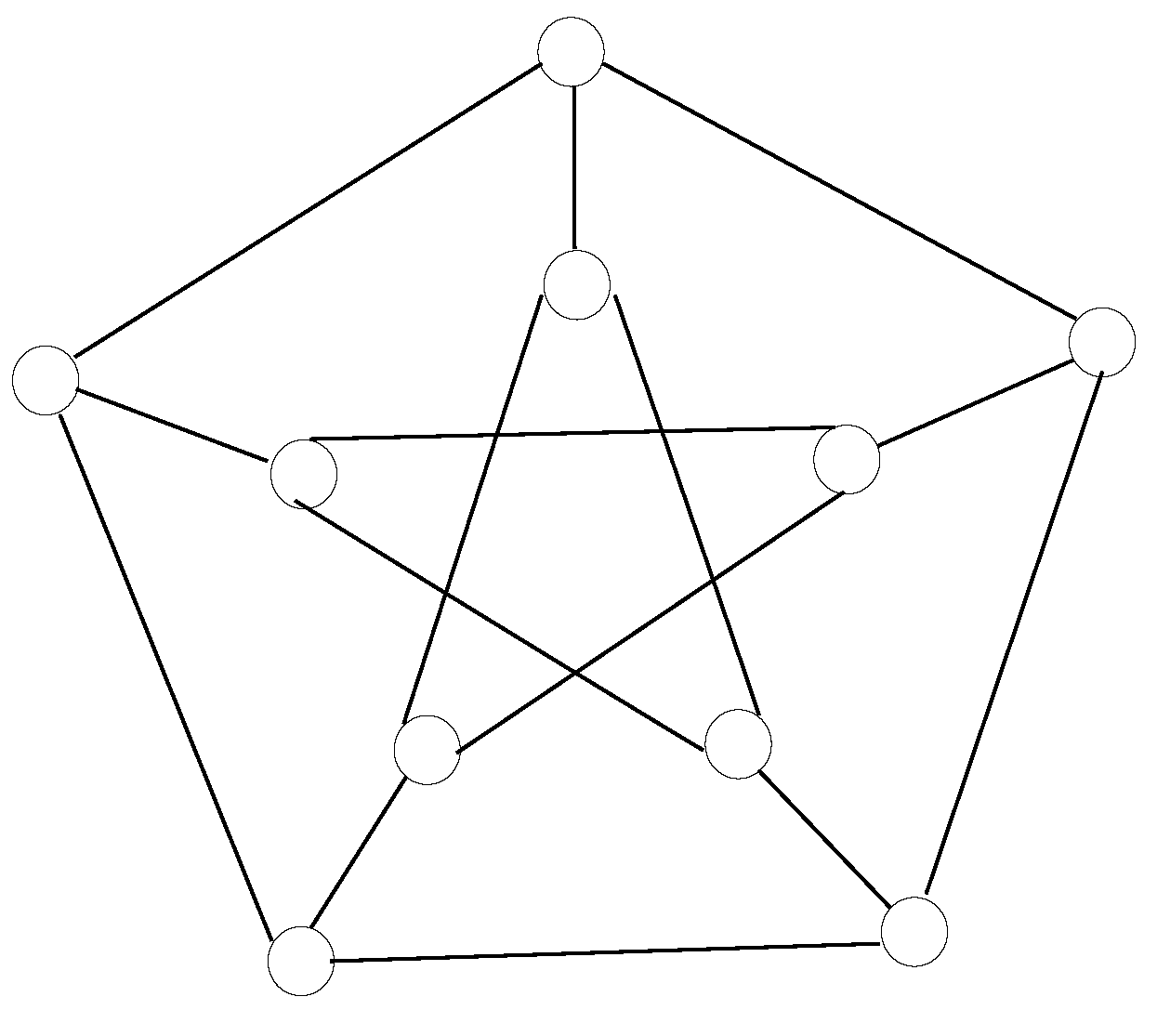
The seventh design is a Petersen graph, which is an instance of a cage graph. It contains 10 nodes connected in a way so that the maximum distance between nodes is two. It is also known as a (3,5)(3,5)-cage, as each node has a degree of three, meaning that all of them have three links towards other nodes, whilst the minimum loop available in the design contains five hops. Figure 10 shows the node disposition in a Petersen graph, wherein two concentric circles are spotted; i.e., the exterior oneis connected as a regular pentagon and the interior oneis linked as a pentagonal star.
Figure 10. Nodes in Petersen graph, a (3,5)(3,5)-cage with 10 nodes.
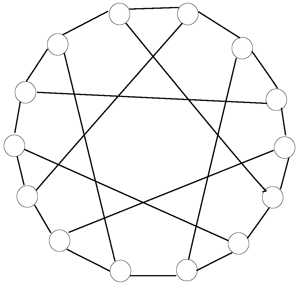
The eighth design is a Heawood graph, which is also a cage graph. It contains 14 nodes interconnected in a way so that the maximum distance among nodes is three. It is also called a (3,6)(3,6)-cage because all nodes have a degree of three, whereas the minimum loop available in the design includes six hops. Figure 11 exhibits the node layout in a Heawood graph, where nodes are disseminated along a circle and secant lines interconnect every five nodes, alternating in clockwise and counterclockwise directions at each neighboring node.
Figure 11. Nodes in Heawood graph, a (3,6)(3,6)-cage with 14 nodes.
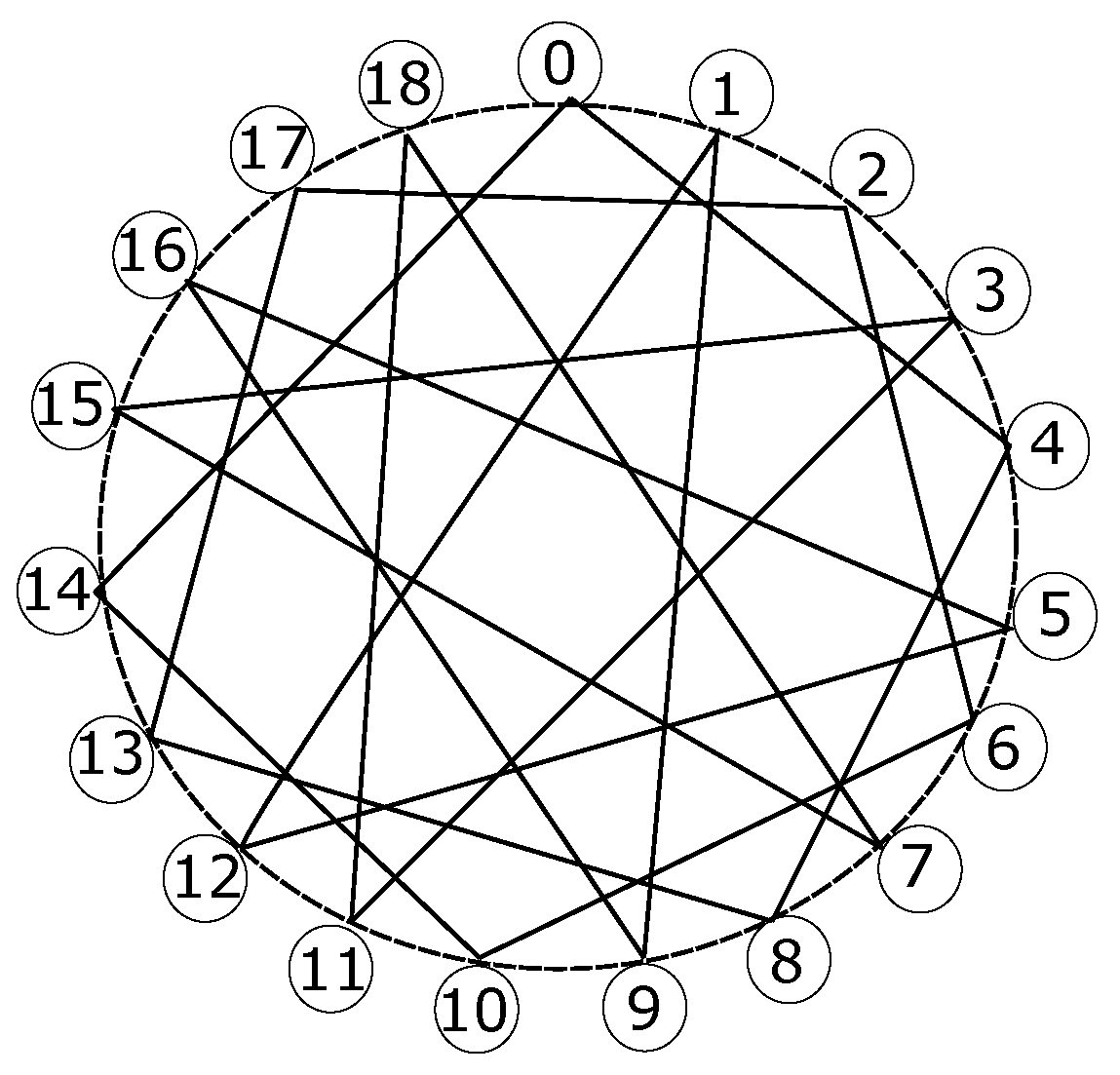
The ninth design is a Robertson graph, which is a cage graph as well. It includes 19 nodes interconnected such that the maximum distance among nodes is three. It is also labeled as a (4,5)(4,5)-cage because every node has a degree of four, whilst the minimum loop available within the topology is five hops. Figure 12 depicts its node layout, where all nodes are spread around an enneadecagon, also known as a 19-gon, and every node has two secant lines interconnecting remote nodes, one of them clockwise and another one counterclockwise, although the ending points of both lines do not appear to follow the same pattern for all cases.
Figure 12. Nodes in Robertson graph, a (4,5)(4,5)-cage with 19 nodes.
3. Other Commonly Used Network Topologies in Data Centers
The following network topologies are typically implemented in large data centers, even though the instances exhibited in this subsection have the parameters set for a small to medium number of servers. Moreover, it is to be noted that all the following designs are tree-like, as they all present a hierarchical structure.
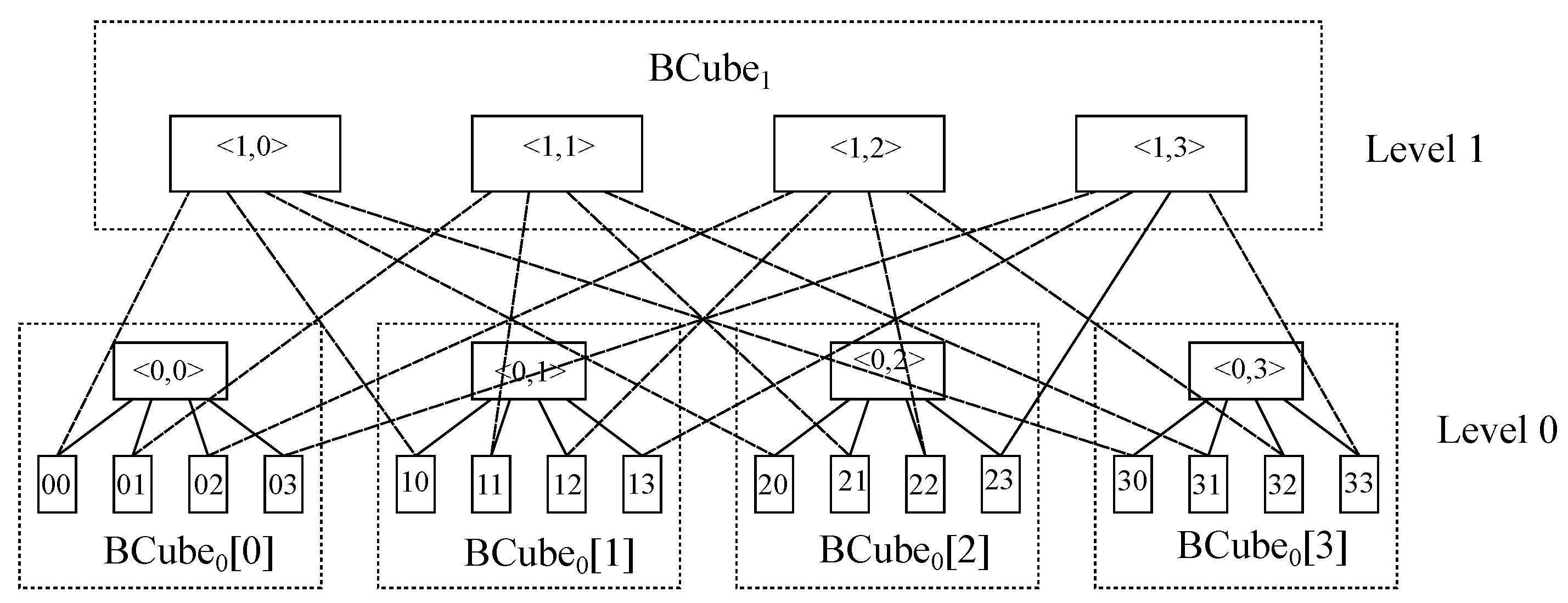
The first design is BCube, which is a recursively defined structure specially designed for modular data centers
[4]. Regarding its construction, it contains nodes with multiple ports and switches connecting a constant number of nodes. To start with, a BCube
00 contains just
n nodes connected via an
n-port switch. Furthermore, a BCube
11 is built up from
n BCube
00 with
nn-port switches and so on. This way, a BCube
𝑘 (𝑘≥1) consists of
n BCube
𝑘−1and
𝑛𝑘n-port switches, with each node having
𝑘+1 ports.
Figure 13 exhibits the node layout in a BCube
11 with
𝑛=4.
Figure 13. Nodes in a BCube11 topology with 𝑛=4.
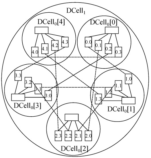
The second design is DCell, which is also a recursively defined structure specifically designed for modular data centers
[5]. The building block for its construction is DCell
00, which has
n nodes and a miniswitch. Further, DCell
11 is made of
𝑛+1 DCell
00 blocks, where each of those is connected to the other DCell
00 blocks with just one link.
Figure 14 depicts the node layout in a DCell
11 with
𝑛=4.
Figure 14. Nodes in a DCell11 topology with 𝑛=4.
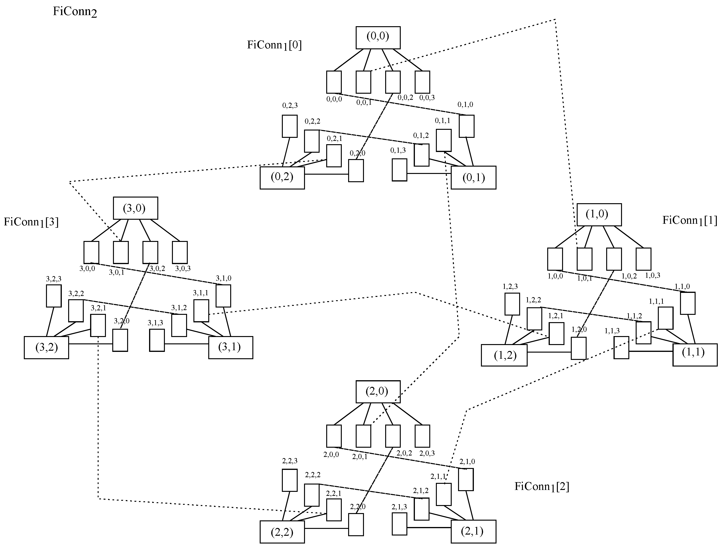
The third design is FiConn, which is a recursively defined structure as well and is properly designed for modular data centers
[6]. It is to be noted that the node degree is always two, which makes interconnection easier than in DCell. The basic construction unit is FiConn
00, and it is composed of
n nodes and
n-port switches, where all
n nodes have their backup port available. Then, to build up FiConn
𝑘(𝑘>0) upon FiConn
𝑘−1, it is necessary to connect the backup ports of nodes among them.
Figure 15 exposes the node layout in FiConn
22 with
𝑛=4.
Figure 15. Nodes in FiConn22 topology with 𝑛=4.
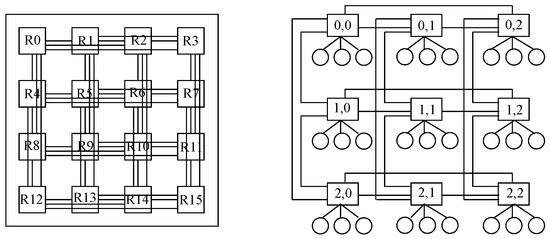
The fourth design is Flattened Butterfly, whose main use is devoted to on-chip networks. Regarding data center network architectures, its main feature is the presence of bypass channels in both horizontal and vertical dimensions, propitiating the employment of non-minimal routing without increasing latency or energy consumption
[7].
Figure 16 presents on the left-hand side a block of 16 switches distributed as a
4×44×4 layout both horizontally and vertically, where any two switches along the same line are direct neighbors thanks to the bypass channels. It is to be noted that each of those switches supports four nodes, although they are not shown in the picture for clarity purposes. Further, on the right-hand side, a block of nine switches distributed as a
3×33×3 layout is depicted, with three hosts hanging on each switch.
Figure 16. Nodes in a Flattened Butterfly topology with 𝑛=4 (left) and 𝑛=3 (right).
The fifth design is DragonFly, which reduces cost by 20% compared to Flattened Butterfly and by 52% compared to folded Clos networks such as fat tree for more than 16K nodes
[8]. Basically, it uses a group of routers with bypass channels among them that acts as a virtual router to increment the effective radix of the network, thus reducing the network diameter, cost and latency.
Figure 17 depicts a Dragonfly topology with
𝑔=9 groups and
𝑎=4 routers within each group. Regarding the number of nodes per router, which is not shown in the picture for simplicity purposes, it should be
𝑝=𝑎/2=2 in order to balance the channel load.
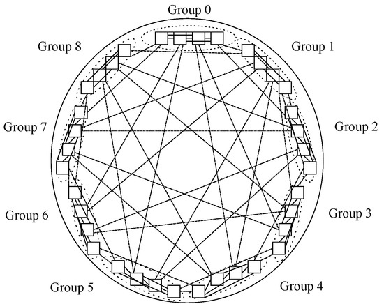
Figure 17. Nodes in a DragonFly topology with 𝑔=9 and 𝑎=4.
The sixth design is SlimFly, which approaches the theoretically optimal network diameter, thus shrinking the average distance among nodes
[9]. This topology is achieved through mathematical optimization looking for the Moore bound in graph theory, reducing more than 50% of routers and 30% of cables with respect to fat tree. It is fit for use in large data centers and high-performance computing (HPC). It obtains a 25% cost and power benefit over DragonFly as well as being more resilient to link failures.
Figure 18 represents a Slim Fly topology where two subgraphs are composed of five groups of routers, and those groups form a fully connected bipartite graph such that each group in one subgraph is connected to all other groups in the other subgraph
[10].
Figure 18. Nodes in a SlimFly topology, with groups of 5 routers forming a fully connected bipartite graph of diameter 2.
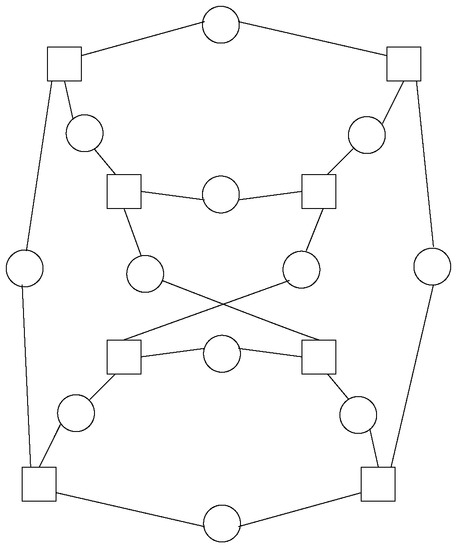
The seventh design is BCDC, which is a server-centric data center network topology based on crossed cubes
[11]. This is a decentralized and recursively defined structure where servers have a constant degree, which possesses an advantage over DCell or BCube in this sense whilst getting better results than them.
Figure 19 exposes a three-dimensional BCDC topology where switches are shown as squares and hosts are circles and with all switches having three ports and all servers having two.
Figure 19. Nodes in a BCDC topology in 3 dimensions.
The eighth design is P-Cube, also labeled as parallel cubes; it is a duplicate structure with a highly scalable and efficient network structure that outperforms Fat Tree, BCube and DCell in terms of network throughput and latency
[12].
Figure 20 shows a P-Cube network topology where
𝑛=4 and switches are represented by squares and servers are shown as circles.
Figure 20. Nodes in a P-Cube topology with 𝑛=4.
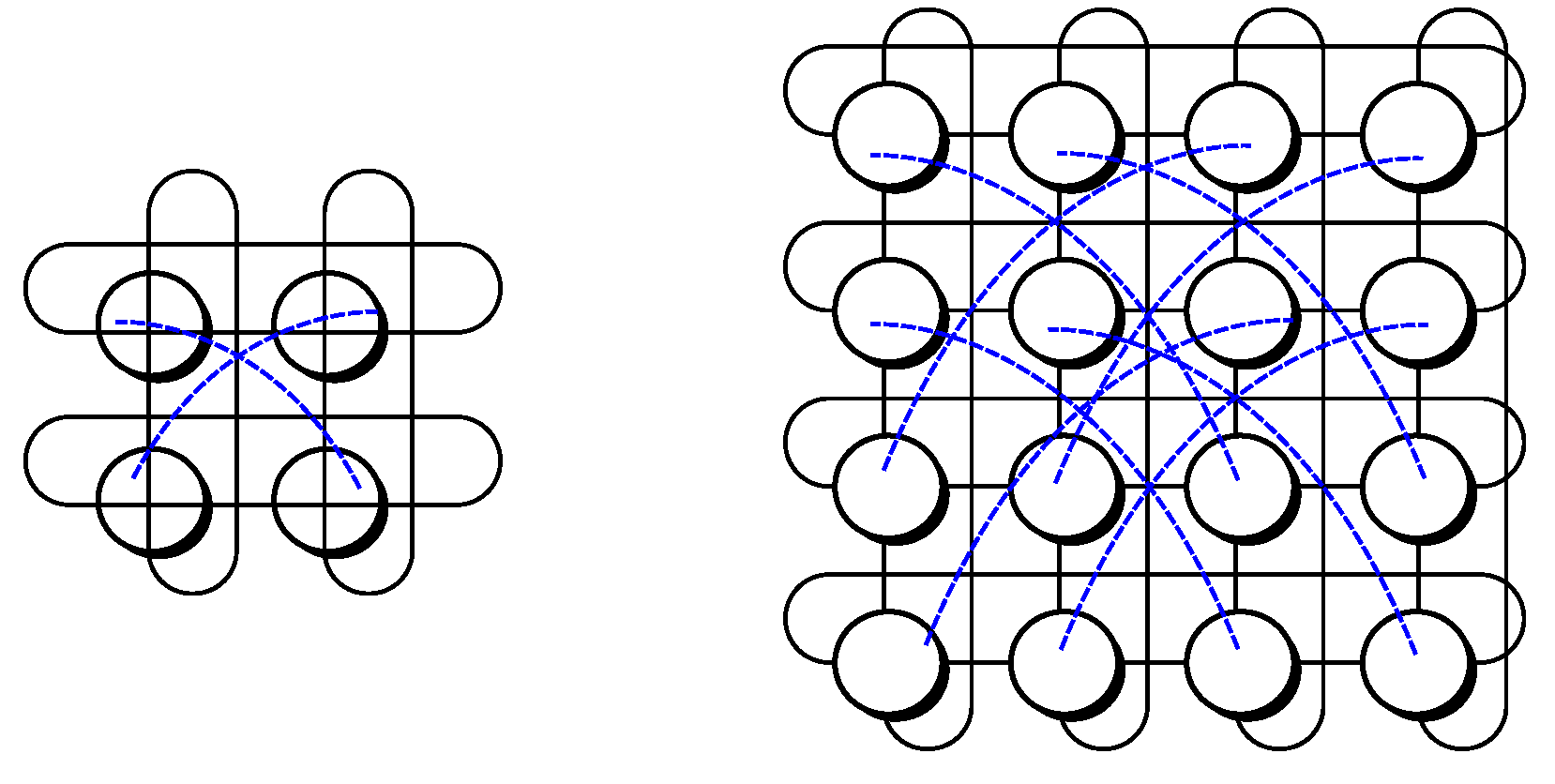
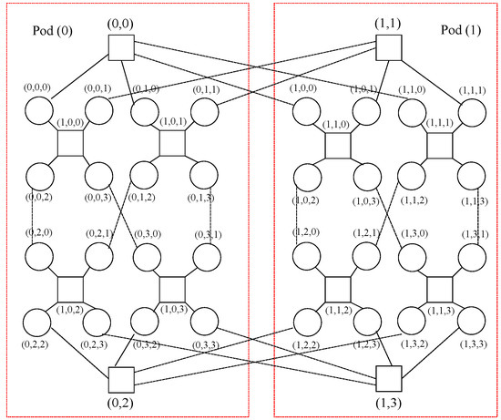
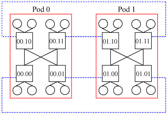
The ninth design is DCCube, which is a compound graph with the disc-ring graph and the crossed cube CQ
𝑛 [13]. It supports a large number of nodes and has high bisection bandwidth, low cost and a small diameter.
Figure 21 shows an instance with one dimension
(𝑘=1), four switches per pod
(𝑚=4), one port per switch pointing to other pods
(ℎ=1) and two servers connected per switch
(𝑐=2), although many other combinations may be undertaken. It is to be noted that black solid lines represent links within a given pod, whilst blue dotted lines show links among pods, whereas red solid lines indicate the boundaries of each pod.
Figure 21. Nodes in a DCCube topology with 𝑘=1, 𝑚=4, ℎ=1 and 𝑐=2.
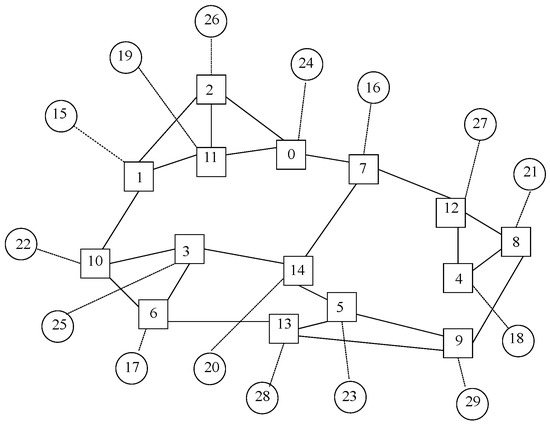
The tenth design is Jellyfish network, which adopts a random regular graph (RRG) as its topology
[14] and has been provento outperform fat tree
[15]. Jellyfish may be specified with three parameters, such as the number of switches
(𝑁), the number of ports in each switch
(𝑥) and the number of ports in each switch connecting to other switches
(𝑦), thus resulting in
𝑥−𝑦 nodes connected to each switch. It happens that when
N and
y are large enough, different instances have similar features.
Figure 22 exhibits a Jellyfish instance with
𝑁=15,
𝑥=4 and
𝑦=3, where switches are denoted as squares and nodes are shown as circles. It is to be said that switches and nodes have been separately identified in a random manner within the picture, starting from zero onwards for each type of element.
Figure 22. Nodes in a Jellyfish topology with 𝑁=15, 𝑥=4 and 𝑦=3.
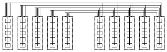
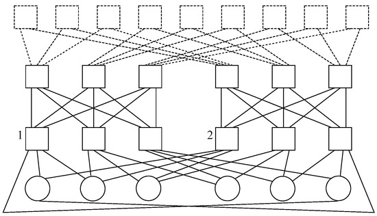
The eleventh design presents Subways, which is a novel approach based on wiring servers to Top-of-Rack (ToR) switches located in neighboring racks
[16]. This way, instead of having all links connected to the same ToR, an overlapping pattern is used for neighboring racks. The advantages of doing so are a decrease in traffic in the inter-ToR network whilst ensuring that the remaining traffic is well-balanced.
Figure 23 exhibits a cluster with a Type-1 subway architecture with
𝑝= and
𝑙=3, where the former is the number of ports per server and the latter is the number of racks in a single Subway loop. It is to be mentioned that two clusters are involved in the topology, where the left one is identified as 1 and the right one is done as 2.
Figure 23. Nodes in a Subway topology with 𝑝=3 and 𝑙=3.
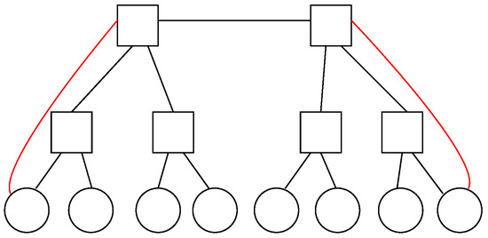
The twelfth design exposes Superways, which is an approach wherein higher bandwidth is provided for some servers to absorb incasts due to the aggregation of responses from other servers
[17]. When doing so, the packet drop rate decreases whilst fault tolerance and throughput are improved; further, the total cost of implementation is reduced compared to other schemes such as Subways.
Figure 24 depicts a Superways scheme, wherein
𝐿=2 represents the number of additional links, which accounts for the minimum number of additional links to avoid packet drops.
Figure 24. Nodes in a Superways topology with 𝐿=2.
In summary, these data center network topologies represent a wide variety of the current architectures being employed nowadays. It is important to remark that the pictures shown herein correspond to small deployments, although all designs may be escalated to accommodate large data centers by including the necessary number of switches and servers.
 +1 credit