Your browser does not fully support modern features. Please upgrade for a smoother experience.
Submitted Successfully!
 +1 credit
Thank you for your contribution! You can also upload a video entry or images related to this topic.
For video creation, please contact our Academic Video Service.
| Version | Summary | Created by | Modification | Content Size | Created at | Operation |
|---|---|---|---|---|---|---|
| 1 | Asjad Ali | -- | 4835 | 2023-07-05 12:11:55 | | | |
| 2 | Conner Chen | Meta information modification | 4835 | 2023-07-06 07:12:48 | | |
Video Upload Options
We provide professional Academic Video Service to translate complex research into visually appealing presentations. Would you like to try it?
Cite
If you have any further questions, please contact Encyclopedia Editorial Office.
Nazir, S.; Ali, A.; Aftab, A.; Muqeet, H.A.; Mirsaeidi, S.; Zhang, J. Development of the Generation of Solar Cells. Encyclopedia. Available online: https://encyclopedia.pub/entry/46452 (accessed on 22 July 2026).
Nazir S, Ali A, Aftab A, Muqeet HA, Mirsaeidi S, Zhang J. Development of the Generation of Solar Cells. Encyclopedia. Available at: https://encyclopedia.pub/entry/46452. Accessed July 22, 2026.
Nazir, Shoaib, Asjad Ali, Abdullah Aftab, Hafiz Abdul Muqeet, Sohrab Mirsaeidi, Jian-Min Zhang. "Development of the Generation of Solar Cells" Encyclopedia, https://encyclopedia.pub/entry/46452 (accessed July 22, 2026).
Nazir, S., Ali, A., Aftab, A., Muqeet, H.A., Mirsaeidi, S., & Zhang, J. (2023, July 05). Development of the Generation of Solar Cells. In Encyclopedia. https://encyclopedia.pub/entry/46452
Nazir, Shoaib, et al. "Development of the Generation of Solar Cells." Encyclopedia. Web. 05 July, 2023.
Copy Citation
Solar energy is of prime importance in all renewable energy sources as the Sun shines at the Earth for 8 to 10 h on average. Thus, heat can be harnessed to generate electricity, but solar cells are not substantially efficient because the materials used in them are quite costly and waste a considerable amount of energy, mostly as heat, which subsequently reduces the efficiency of the cell and increases the overall price as well. These challenges can be dealt with by designing more efficient, economical systems of storage and manufacturing PV cells with high efficacy. Scientists and engineers are more inclined toward advanced technologies and material manipulation to enhance the efficiency of solar energy and reduce its cost.
nanomaterials
solar energy
carbon-based nanomaterials
1. First-Generation Solar Cells
Wafer-based solar cells: It is quite evident from a historical perspective that the oldest material that is employed in solar cells all over the world is silicon because of its abundance in nature and band gap energy of around 1.17 eV. The manufacture of incipient Si solar cells gave rise to first-generation solar cells. These devices consisted of semiconductors with a p-n junction and are considered to be the most dominating solar cells in the market because of the excessive availability of high-quality silicon and its usage in microchips [1]. After the invention of solar cells based on silicon back in 1954, the efficiency of solar cells has been a major problem, and substantial research has been carried out on this. The initially estimated efficiency of these cells was around 22%. Efficiency mainly depends upon the band gap of solar cells, which is around (~15–22%) for crystalline solar cells.
There are some other factors that, if accounted for, reduce the efficiency of solar cells considerably compared to the estimated solar cell’s efficiency. The physical structure of cells contributes substantially to the determination of solar efficiency. Based on physical structure, solar cells are categorized as mono-crystalline or polycrystalline [2]. Mono-silicon crystals are made from single silicon crystals via a process called the “Czocharlski Process”. In this process, large crystals are sliced and recrystallized, and this is a sophisticated process that requires precision, which increases the price of mono-crystal solar cells. The efficiency of these cells is 26.1%. Mono-crystalline solar cells exhibit stability, high performance, and long life. The major problems with these cells are that they are sensitive to temperature, have high production costs and there is material loss during the manufacturing process [3]. Polycrystalline cells consist of multiple crystals joined together to form a single cell. This process is more economical compared to mono crystals. Silicon is molded into a graphite mold, which is further cooled. Polycrystalline cells are most widely used all around the globe because they have low production costs [4]. To reduce the price and enhance the efficiency of first-generation solar cells, emitter wrap-through solar cells were implemented. Using this technology, both the fill factor and efficiency increased. A sequential simplified process is employed instead of back-to-back junction solar cells, and high open-circuit voltages are obtained. Resistance is also optimized in the path between the base and emitter to improve the overall fill factor [5]. An experiment was conducted in 2011 for n-type silicon solar cells, and an efficiency of around 21.6% was achieved [6]. The latest achieved efficiency of multi-crystalline solar cells is 23.3% [7]. Compared to mono-crystalline solar cells, polycrystalline cells are simple to manufacture and economical, and during production, lower amounts of materials are squandered, and they have better electrical characteristics. The drawbacks of these cells include higher sensitivity to temperature and decreased efficiency [1][8]. Overall, first-generation solar cells have matured and are more efficient at lower temperatures, and they produce more power per unit. They also occupy more of the market compared to any other generation of solar cells. The main disadvantage of this generation is their poor performance at high temperatures.
2. Second-Generation Solar Cells
Thin-film solar cells are regarded as second-generation solar cells and are praised for being more affordable than the previous generation. They have light-absorbing layers measuring around 1 micrometer in thickness [9]. They are divided into three categories: amorphous silicon, cadmium telluride (CdTe), and copper indium gallium di-selenide (CIGS).
2.1. Amorphous Silicon Thin Films
Amorphous silicon (a-Si) solar cells are the most rudimentary solar cells that were developed at the industrial scale. They can be fashioned at very low temperatures, resulting in many low-cost polymers and substrates that have highly flexible applications. They are widely available because of their low cost. As evident from the name, they have disarranged non-crystalline lattice structures [10]. As for their disordered and dangling atomic structure, their charge carrier mobility is quite poor. This is one of the main reasons why mono-crystalline solar wafers made of silicon are more efficient than both thin-film amorphous silicon cells and polycrystalline cells. They are created by covering the doped silicon on the substrate’s back. These solar cells have a silvery conductive side, and the reflective side is usually brown. Although they have low costs, their efficiency is also low, and the efficiency of amorphous silicon solar cells has a theoretical limit of about 15% [11]. Amorphous silicon is not a prolific semiconductor when it comes to efficiency, but if hydrogen is added to the structure, efficiency improves considerably. By adding hydrogen, the suspended sites in amorphous silicon establish bonds with hydrogen, and as a result of this, photoconductivity is enhanced. The optically optimized cell, which is the best-in-class amorphous solar cell, achieved an energy conversion efficiency of 14% [12]. The comparison of efficiency in all three technologies based on silicon is compared in Figure 1. One of the major drawbacks of a-Si is the degradation they experience as they are deployed, and this persists over a period of time. The degradation of a-Si:H was studied by Osayemwenre and Meye, and they observed that efficiency decreased considerably during the monitored time period. Efficiency was reduced by 0.2% with each degree of increase in temperature [13].
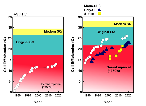
Figure 1. Efficiency of solar cells from 1975 to 2022.
Figure 1 describes the efficiency of silicon-based solar cells from 1975 to 2022. The theoretically calculated efficiency of various silicon solar cells is also depicted. The Shockley–Queisser limit is around 33% for pure silicon solar cells. The semiempirical efficiency is 22%, and the original efficiency value is 30%. Monocrystalline solar cells and polycrystalline solar cells exhibited almost the same efficiency of around 14% in 1980; currently, monocrystalline solar cells have reached an efficiency of around 26%, while the efficiency of polycrystalline is measured at 24%. Hydrogenated silicon solar cells have a semiempirical solar cell efficiency of around 18%. The original value of efficiency was 27%, while the modern value measures up to 28%. Currently, a-Si:H racked up the highest efficiency of 14%.
2.2. Cadmium Telluride Thin Solar Film (CdTe)
Another type of solar cell that is being developed under the spectrum of second-generation solar cells comprises cells that are composed of cadmium telluride. Cadmium telluride is a perfect material for making polycrystalline solar cells because of its optoelectronic and chemical properties, and it would have low costs as well. CdTe is a direct band gap material with a band gap value of 1.5 eV and an absorption coefficient of ~105/cm in the visible region, subsequently making it a perfect absorber for around 90% of the incident light, and it measures only a few millimeters in thickness. This is because high-temperature deposition films are usually deposited with lower quantities of Cd, which gives rise to p-type conductivity. Due to the increased number of ions (around 70%) in CdTe, the crystals are usually more passivated, and they exhibit rugged chemical bonding and around 5.75 eV with respect to energy, which imparts increased chemical and thermal stability upon them. It has been demonstrated that CdTe solar cells are exceptionally resistant to deposition techniques. Solar cells are made based on CdTe junctions [14]. The record laboratory efficiency for a CdTe solar cell is 22.1% even though their supposedly predicted efficiency is about 33% [15]. In 25 years, their efficiency has been boosted from 15.8% [16] to 22.1% [7][17]. The slow progress in efficiency boost is because of the lack of R & D with respect to CdTe, and this is perhaps due to concerns regarding the environment and its toxicity [18][19].
2.3. Copper Indium Gallium Di-Selenide (CIGS) Solar Cells
CIGS solar cells were first developed in 1974 in the laboratory with an initial efficiency of around 6%. In 1975, by adding CdS to CIGS, efficiency galloped to 12%, which exhibited the potential of the material’s development on an industrial scale. CdS is an n-type semiconductor material, and when added to CIGS, it acts as a buffer layer, which subsequently allows the separation of charge carriers. In an experiment in 2017 at the University of Santa Clara, the United States, four buffer layers (InS, ZnO, ZnS, and ZnSe) instead of CdS were employed in CIGS cells, and it was observed that ZnS turned out to be better among all competitors with an efficiency of around 20.7% [20][21]. CIGS has some exceptional photovoltaic properties like greater absorption coefficient and high radiation tolerance, which makes it quite a suitable material for applications in solar cells [22]. Sulfur in these solar cells has a very rapid diffusion rate during deposition, even at lower temperatures, which halts the fabrication and development of these cells [23][24]. Sputtering, evaporation, electrochemical coating, printing, and electron beam deposition are methods used to treat CIGS. Sputtering can either be a one-step reactive process or a two-step procedure that involves first depositing the material and then interacting with selenium. Evaporation can be carried out with multiple steps or single steps, similarly to sputtering. The substrate that is used for CIGS technology can either be glass, polymer, steel, or aluminum. The advantages of using CIGS include higher efficiency and a low degradation rate, which means that these solar cells would have longer life [25][26][27]. CuInSe2 has a more benign nature from an electrical perspective, and its band gap can also be varied depending on the light spectrum, subsequently making it an indispensable material for enhancing efficiency. CuInSe2 films are an equally effective kind of electrical material compared to their single crystalline cousin. Due to this characteristic, the material is less sensitive to impurities, grain size, and crystalline flaws. An efficiency of around 22.8% [28] was achieved compared to crystalline silicon (c-Si)-wafer-based solar cells [29] for small areas, and 15% efficiency was achieved for large areas by tailoring the band gap according to the spectrum of light. Superior performance can be attained by matching the junction with the band gap energy of the solar spectrum. The latest achieved efficiency for CIGS solar cells is 23.6%, as reported by NREL [7]. Although these cells have achieved remarkable efficiencies and promise a bright future in enhancing efficiency, due to the usage of alloy in their formation, some intricate processes are involved, and they require precise control during deposition and composition, which is not easy to achieve. The modules are also vulnerable to water ingress, and humidity can jeopardize the stability of non-encapsulated CIGS solar cells [30]. The utilization of materials like indium and gallium also increases the overall cost. Figure 2 shows an Excel graph plotted using values acquired from NREL, and it shows the overall efficiencies of second-generation solar cells.

Figure 2. Efficiency of thin film technology.
The graph above shows the efficiency of thin film technology within the span of four decades. Yellow, orange, and green colors show the efficiency trends of cadmium telluride, copper indium gallium, and hydrogenated solar cells from 1976 to 2022.
3. Third-Generation Solar Cells
Third-generation solar cells are the successors of the second generation, and they promise greater efficiency at lower costs. The major purpose behind the creation of this generation is to surmount the shortcomings of the second generation. One of the remarkable advantages of this generation is the fallout of power costs from 80% to 50% at larger scales compared to second-generation solar cells. The other major advantage is that this generation utilizes a variety of materials, like organic materials, dyes, perovskites, and quantum dots, whereas the second generation only uses CdTe and CIGS. Under the umbrella of third-generation solar cells, various cells have been developed, with promising results. Third-generation cells entail organic solar cells, dye-sensitized solar cells, quantum dot solar cells, perovskite cells, and nanomaterial-based solar cells, which are explained in detail in the upcoming sections.
3.1. Organic Solar Cells
These solar cells use organic materials such as polymers and small molecules as active layers. They are cheap to manufacture, flexible, and lightweight. The general materials used for PV solar cells comprised inorganic materials. Thus, research studies are conducted to find new ways of improving efficiencies by developing novel materials. After the formation of a semiconducting polymer, these materials were incorporated into organic solar cells, which showed an unexpected improvement. This kept costs low and boosted performances beyond conventional materials [31]. Organic solar panels mainly consist of at least four layers with a translucent substrate, as shown in Figure 3. The substrate is used to protect materials from impurities, and the device is illuminated through this substrate. It could be made up of glass or polyester. In organic solar cells, a donor–acceptor heterostructure is formed by donor–acceptor moieties, which come into close contact with each other to form an organic solar cell. When a donor absorbs a photon with sufficient energy, the electron leaps into the lowest unoccupied molecular orbital (LUMO), rendering a hole in the highest occupied molecular orbital (HUMO), and this engenders an exciton.

Figure 3. Schematic diagram for a typical basic organic cell with CNTs as acceptors within the active layer.
The difference in energy between the orbitals determines which wavelength of light would be absorbed. Unless immediately separated, the exciton recombines. To dissolve the exciton, the acceptor material must offset the exciton’s binding energy in the donor. The charge transfer at the interface is only possible if the following conditions are met:
where EA stands for electron affinity, and UD stands for the exciton’s binding energy in the donor; the acceptor and donors are represented by superscripts A and D. The electron generated from a photon of light moves to the acceptor’s LUMO if the acceptor exhibits greater electron affinity compared to the donor. Moreover, organic semiconductors exhibit lower charge carrier motilities compared to inorganic semiconductors. Organic solar cells fall behind traditional silicon PV as their highest single-junction solar cell reached a PCE of 19.2%. On the other hand, single-junction silicon solar cells surpassed the efficiency by 35.5%, reflecting the highest performance [32][33][34]. As PCEs in laboratory-scale devices (1 mm2) reach the target of 20%, vast-area device modules with moderate PCEs have been produced. The PCE for a module is commonly known to exhibit roughly 5% less efficiency than that of laboratory-scale devices in the OSC sector. In recent papers, a power conversion efficiency (PCE) of 5.6% was obtained by using a module with an active area of 216 cm2 (16 elementary cells are coupled), and this is a key step toward large-scale organic solar cell applications [35]. The reason for the lower efficiency is the additional assistance (energetic cost) needed to separate and extract charges. Although most leading companies are making significant progress in large-surface-area deposition and encapsulation, scaling from small devices remains a challenge today. Critical efficiency, the stability of the device under ambient working conditions, enhanced lifetime, low-cost production technologies for mass production, and a greater absorption coefficient are considered major challenges that need to be overcome in emerging and efficient organic solar cells (OSCs). To improve these critical aspects, many researchers, scientists, and academics are working to commercialize this new technology and obtain feasible standards with respect to efficiency, reliability, and stability. The major strength of organic photovoltaic cells is their higher throughput and lower cost, but they cannot be marked as superior with respect to performance.
EAA − EDA > UD
3.2. Dye-Sensitized Solar Cells
DSSCs are electrochemical cells that mimic plants for energy production. Energy is harnessed by the combined effect of chemical processes and light energy. These solar cells use a layer of dye molecules to absorb light and transfer electrons to a semiconductor material. It is potentially cheaper and more efficient than conventional silicon solar cells [36][37]. DSSC uses a photo anode, sensitizer, electrolyte, and counter electrode. Light is absorbed by a sensitizer, which is fastened to the surface of a wide-band semiconductor. At the interface, charge separation happens via the injection of photo-induced electrons from the dye into the solid’s conduction band [38]. Carriers are carried to the charge collector via the semiconductor’s conduction band. By combining sensitizers with a wide absorption band with oxide coatings with a nano-crystalline shape, a considerable amount of sunlight can be absorbed. The quantitative conversion of incident light photons to electric current is accomplished over a broad spectral range stretching from UV to near-IR areas [39]. The conventional manifestation of dye-sensitized solar cells consists of two translucent conducting oxide (TCO)-coated glass electrodes; typically, the substrate glass is coated with fluorine-doped tin oxide (FTO). Among these, one of the substrates is coated with a photo electrode (PE) made of 10–15-micrometer-thick layer of interconnected titanium dioxide (TiO2) particles that are sensitized using dye molecules usually comprising an organometallic compound made of ruthenium. The other substrate is coated with a catalyst, such as platinum, and works as a counter electrode (CE). To prevent short-circuiting between both electrodes, they are segregated via a thermoplastic spacer or a thick and porous insulating layer [37]. During the operation of these cells, by using a liquid electrolyte that contains a redox mediator that is usually made up of iodide/triiodide-based redox shuttles, charges are exchanged between both PE and CE. The mediator is diffused not only through the porous TiO2 electrode but also through the porous spacer and the large phase of the electrolyte as well. Therefore, the thickness of the thermoplastic spacer and porous insulator directly impacts the performance of dye-sensitized solar cells via mass transport and the diffusion resistance of the bulk electrolyte [37]. Under typical conditions, the best co-sensitized solar cells demonstrated a power conversion efficiency of 15.2%, while larger devices with an active area of 2.8 cm2 demonstrated an even greater efficiency ranging from 28.4% to 30.2%. These outcomes are outstanding and show the capability of DSSCs for high efficiency [40].
3.3. Perovskite Solar Cells
These solar cells use a class of crystalline materials called perovskites to absorb light and generate electricity. By absorbing light over a wider spectrum of wavelengths, multijunction (tandem) solar cells (TSCs), which are made up of several light absorbers with noticeably distinct band gaps, have significant potential with respect to surpassing the Shockley–Queisser (S-Q) efficiency limit of a single-junction solar cell [41]. Due to their customizable band gaps, high PCE of up to 25.8%, and simple manufacturing process, perovskite solar cells (PSCs) are excellent candidates for TSCs. Narrow-band-gap PSCs and dye-sensitized, organic, and quantum dot solar cells are just a few of the numerous solar cell types that can be easily combined with PSCs with high PCEs, which are commonly made by using a low-temperature solution approach. In fact, since their initial invention, perovskite TSCs have sparked tremendous interest in science and the industry [42]. Figure 4 explains the composition of materials in thin-film perovskite solar cells and perovskite deposited on silicon tandem solar cells.
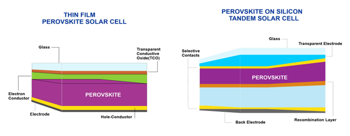
Figure 4. Material composition of thin-film perovskite solar cells vs. perovskite on silicon tandem solar cells.
Excellent light absorption, charge-carrier mobilities, and lifetimes provided by perovskite materials lead to high device efficiencies and potentially low-cost, commercially viable technologies. Furthermore, via the unique control of optoelectronic properties, perovskite thin-film technology has the potential to reach the theoretical efficiency limit for single-junction solar cells [43]. Device stability and device upscaling are two constraints that prevent perovskite solar cells from becoming commercially viable. Temperature [44], humidity [45], composition [46], and light [47] are all elements that contribute to degradation [43]. These cause material degradation and a decline in performance over time. We must overcome obstacles relating to stability and environmental compatibility in order to accomplish this promise, but if these issues are resolved, perovskite-based technology holds revolutionary potential for quick terawatt-scale solar deployment. Due to the fundamental features of the material, hybrid perovskite solar semiconductors are being studied for their usage in a broader class of energy applications, which extends beyond conventional electrical and optical systems. Perovskite materials’ superior light absorption, charge-carrier mobility, and lifetimes result in high device efficiencies and the possibility of a cheap, marketable technology. Obstacles relating to stability and environmental compatibility need to be overcome to realize this potential, but if these issues are addressed, perovskite can be used [48].
Perovskite has attracted global attention due to its remarkable efficiency growth. Monolithic perovskite/silicon tandem showed consistent improvements in their efficiency in the past decade. As can be seen in Figure 5, in 2018, the performance of the perovskite/SI tandem has risen exponentially within a duration of two years, and it obtained a PCE of 33.7%. In contrast, this was not attained by single-junction perovskite for a decade until now. By analyzing the improvement in efficiency, it can be predicted that the monolithic perovskite tandem has the ability to surpass the Shockley–Queisser limit [49]. After resolving the concerns regarding its stability, it can be manufactured at massive scales that could contribute to decreasing carbon emissions.
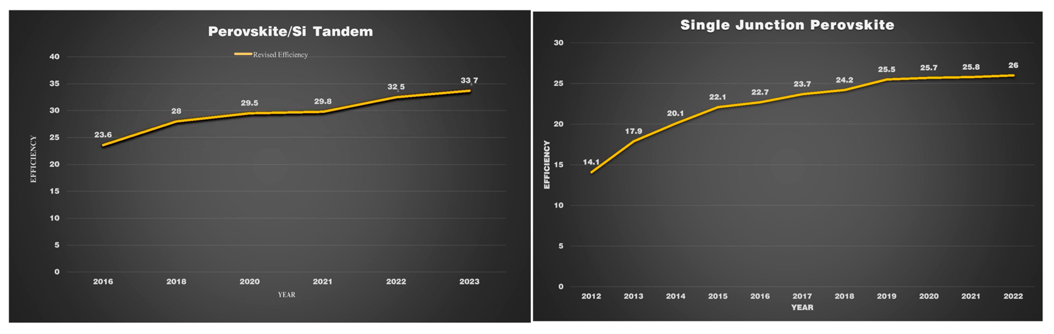
Figure 5. Efficiency records for perovskite PV cells compared to other PV technologies, with current records of 26% for single-junction perovskite devices and 33.7% for tandem perovskite–silicon devices.
3.4. Quantum Dot Solar Cells
These solar cells use tiny semiconductor particles called quantum dots to absorb light and generate electricity. The highest thermodynamic efficiency for turning solar energy into electrical or chemical energy was determined to be 31% by Shockley and Queisser in 1961 [50]. This limit results from the heat-loss processes of electron–phonon scattering and phonon emissions caused by the relaxation of photo-generated hot carriers relative to band edges. Several strategies have been proposed to overcome this restriction, such as stacking numerous cascaded p-n junctions with band gaps that are better matched to the solar spectrum and making use of the hot carriers before they relax in the band’s margins. By generating a higher photovoltage or photocurrent, hot carrier solar cells can improve the efficiency of photon conversion [51]. Hot holes often cool more quickly than hot electrons despite the electrons’ substantially lower effective mass. Hot holes and hot electrons typically cool at different rates, with electrons cooling more slowly due to their substantially lower effective masses. The amount of cooling is also impacted by the density of photo-generated hot carriers [52]. Another initiating point to increase the efficiency of solar cells is to use semiconductor quantum dots. By using quantum dots, the band gap energy can be manipulated to respond to longer light wavelengths, subsequently enhancing the efficiency of solar cells. Quantum cells can produce power at all hours of the day. This is because they can be configured to emit infrared light in addition to visible light even though nighttime generation would be far less abundant than daytime output [53]. As the material for these quantum dots, the conglomeration of different materials is preferred, such as Si/Ge, Si/Be, and Te/Se [46][47]. To enhance the efficiency of solar cells, substantial research has been carried out on the absorption layer of quantum dots. Up until now, an efficiency of around 18.1% has been gained [54]. But, by improving the absorption property of the Si-QD layer, higher efficiency can be achieved, and recent experiments have revealed that higher efficiencies were achieved by carrying this process out. The QD secondary deposition method has been employed in the past to enhance QD loading; however, it creates new recombination centers, which are inefficient for enhancing the photovoltage and fill factor.
New adsorption sites are created without the addition of new recombination centers by adopting the authors’ novel QD secondary deposition method. The QD pre-sensitized photoanodes are surrounded by a metal oxy-hydroxide layer in this method. Zn, Cu, In, S, and Se (ZCISSe) QD-sensitized TiO2 film electrodes were used to research this secondary deposition technique. The experimental results demonstrate that the new strategy enhances QD loading, and as a result, the photocurrent, photovoltage, and fill factor have all significantly improved. ZCISSe QDSCs now have an average power conversion efficiency (PCE) of 15.31%, up from the original 13.54%, and a new certified PCE record of 15.20% for liquid-junction QDSCs has been attained [55]. The development of a metal oxy-hydroxide layer over QD-presentive TiO2-film electrodes allows for secondary depositions without the addition of extra recombination centers. It can be seen in Figure 6, that metal oxide layers have been widely used as barrier layers around pure TiO2-film electrodes in dye-sensitized solar cells (DSCs) to increase sensitizer loading and reduce charge recombination [56][57]. Here, metal oxy-hydroxides were produced from equivalent metal chloride aqueous solutions by a simple hydrolysis and condensation method. It was discovered that the oxy-hydroxides of Mg2+, Ti4+, Ca2+, and Sr2+ could significantly enhance QD loading and produce a profoundly helpful impact on the photovoltaic performance of the corresponding QDSCs.
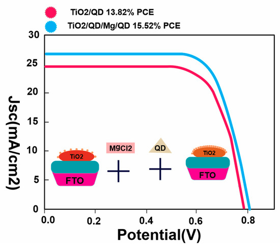
Figure 6. The average PCE of the resulting ZCISSe QDSCs increased from the initial 13.82% to 15.52%.
A thicker photoanode film enhances the loading amount of QD sensitizers and light-harvesting capacity, resulting in a high photocurrent. However, it can also increase the distance for photo-generated electrons to travel and result in undesired charge recombinations, leading to a deterioration of photovoltaic performance. From Figure 7, it can be noted that optimizing the thickness of the photoanode film is significant for high-performance QDSCs. In this study, TiO2-film electrodes containing a transparent TiO2 layer with different thicknesses were prepared, and QDSCs based on these TiO2 films with different thicknesses were constructed. The optimum thickness for the TiO2-film electrode was determined to be 19.0 μm, which resulted in the best photovoltaic performance. The influence of the TiO2 film’s thickness on the performance of TiO2/QD/Mg/QD QDSCs was further investigated using electrochemical impedance spectroscopy (EIS). The results showed that a thin TiO2 film is superior for the suppression of charge recombination, and the charge recombination rate is slower with a larger Rrec value [55].
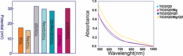
Figure 7. Potential values for different TiO2 QD/Mg/QD samples with three rounds of QD deposition in film electrodes.
Increasing the interaction between the TiO2 matrix and QD would result in high performance. Secondary (TiO2/QD/Mg/QD) deposition has increased the interaction, resulting in higher efficiency due to the creation of new adsorption sites and improved QD loading as seen in Table 1.
Table 1. Photovoltaic parameters of TiO2/QD, TiO2/QD/QD, and TiO2/QD/Mg/QD QDSCs based on Cu2S/Brass CEs [56].
| Photo Anode | Jsc (mA/cm2) | Voc (V) | Fill Factor | PCE (%) |
|---|---|---|---|---|
| TiO2/QD | 24.69 ± 0.27 | 0.634 ± 0.003 | 0.640 ± 0.001 | 10.03 ± 0.07 |
| TiO2/QD/QD | 24.56 ± 0.57 | 0.631 ± 0.002 | 0.639 ± 0.005 | 9.90± 0.19 |
| TiO2/QD/Mg/QD | 26.79 ± 0.16 | 0.644 ± 0.003 | 0.652 ± 0.001 | 11.25 ± 0.10 |
| TiO2/QD | 25.03 | 0.632 | 0.637 | 10.11 |
| TiO2/QD/QD | 25.19 | 0.634 | 0.634 | 10.12 |
| TiO2/QD/Mg/QD | 27.03 | 0.645 | 0.651 | 11.35 |
Quantum dots are also inexpensive, and multi-function cells use a hybrid design to make them more stable and efficient compared to polymers and have overall reduced power consumption. Substantial R&D operations still need to be carried out, and financing might be a concern for several companies, but quantum dots could potentially beat conventional silicon PV cells.
3.5. Concentrated Solar Cells
Normally, PV cells respond efficiently to direct sunlight, but most light in the designed environment is diffused as phenomena like scattering and reflections due to buildings, trees, clouds, and shade, which most commonly reduce the efficiency of cells. To combat these challenges, concentrated solar cells play a significant role. Concentrated solar cells were first developed in 1974, and the concept has become quite dominant in the market after 2010 [58][59]. The basic idea behind concentrated solar cells is to focus the maximum amount of light onto a very small area above the PV cell, as depicted in Figure 8. Using the same principle as utilized in optics, sunlight is concentrated onto a specific area by using mirrors and lenses. Hence, a massive amount of heat energy is produced by focused solar radiation [60]. When a solar cell is subjected to a concentrated solar light, it generates more current per area; hence, efficiency increases. Voltage increases logarithmically and so does efficiency. In the realm of solar PV cells, concentrated solar cells have shown considerable potential. Concentrated solar cells are advantageous in many ways as they entail solar cells that have an efficiency of more than 40%, no moving components, little thermal bulk, quick response times, and scalability to a variety of sizes [61]. It is expected that concentrated solar cells would be installed in large numbers in sunbelt countries by 2030. Because light is specifically concentrated in these cells, this increases the temperature of the overall cell despite employing the best cooling efforts. Usual heat sinks or other cooling systems are utilized with concentrated solar cells to decrease the overall temperature of solar cells. For instance, organic and silicon solar cells are sensitive to heat, so if a concentrator and a tracking system are utilized with these cells, excessive heat can be detrimental to these cells. For these cells, a low-concentration system (1–100 sun) is used, which does not require a tracking system, and this reduces the overall price as well. In the same way, medium–high concentration systems are utilized using gallium arsenide and multijunction solar cells. These cells perform well under high temperatures and have also exhibited high conversion efficiencies [62][63]. Concentrated solar cells have substantial potential in achieving carbon reduction at low prices if high-voltage DC infrastructure is readily available [64].
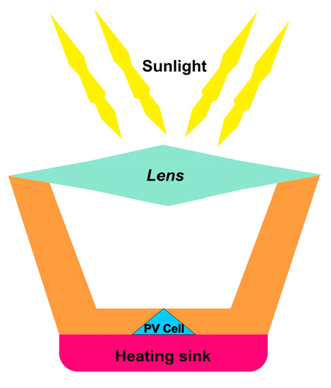
Figure 8. Schematic of the concentrated solar cell.
Figure 8 above shows the schematic for concentrated solar cell technology. Light hits the lens and is concentrated in solar cells. The heat sink keeps the solar cell from becoming hot to avoid burning and hot spot formation.
References
- Mercaldo, L.V.; Veneri, P.D. Silicon solar cells: Materials, technologies, architectures. Sol. Cells Light Manag. Mater. Strateg. Sustain. 2020, 1, 35–57.
- Sethi, V.K.; Pandey, M.; Shukla, P. Cost Boundary in Silicon Solar Panel. Int. J. Chem. Eng. Appl. 2011, 2, 372–375.
- Sharma, P.; Goyal, P. Evolution of PV technology from conventional to nano-materials. Mater. Today Proc. 2020, 28, 1593–1597.
- Jayakumar, P. Solar Energy Resource Assessment Handbook; Asian and Pacific Centre for Transfer of Technology: Delhi, India, 2009; pp. 1–117.
- Balaji, N.; Hussain, S.Q.; Park, C.; Raja, J.; Yi, J.; Jeyakumar, R. Surface passivation schemes for high-efficiency c-Si solar cells—A review. Trans. Electr. Electron. Mater. 2015, 16, 227–233.
- Kiefer, F.; Ulzhöfer, C.; Brendemühl, T.; Harder, N.P.; Brendel, R.; Mertens, V.; Bordihn, S.; Peters, C.; Müller, J.W. High efficiency N-type emitter-wrap-through silicon solar cells. IEEE J. Photovolt. 2011, 1, 49–53.
- National Renewable Energy Laboratory (NREL). Best Research-Cell Efficiencies Best Research-Cell Efficiency Chart Photovoltaic Research; NREL: Golden, CO, USA, 2021.
- Al-Ezzi, A.S.; Ansari, M.N.M. Photovoltaic Solar Cells: A Review. Appl. Syst. Innov. 2022, 5, 67.
- Salve, R.V. State of Art of Thin Film Photovoltic Cell: A Review. Int. J. Sci. Res. Sci. Technol. 2020, 7, 157–163.
- Imamzai, M.; Aghaei, M.; Thayoob, Y.H. A Review on Comparison between Traditional Silicon Solar Cells and Thin-Film CdTe Solar Cell. Proc. Natl. Grad. Conf. 2011, 2012, 8–10.
- Sharma, S.; Jain, K.K.; Sharma, A. Solar Cells: In Research and Applications—A Review. Mater. Sci. Appl. 2015, 06, 1145–1155.
- Kang, H. Crystalline Silicon vs. Amorphous Silicon: The Significance of Structural Differences in Photovoltaic Applications. IOP Conf. Ser. Earth Environ. Sci. 2021, 726, 6–11.
- Osayemwenre, G.O.; Meyer, E.L. Confirmation of the Degradation of Single Junction Amorphous Silicon Modules (a-Si:H). Int. J. Photoenergy 2019, 2019, 3452180.
- Efaz1, E.T.; Rhaman, M.M.; Al Imam, S.; Bashar, K.L.; Kabir, F.; Mourtaza, M.E.; Sakib, S.N.; Mozahid, F.A. A review of primary technologies of thin-film solar cells. Eng. Res. Express 2021, 3, 032001.
- Report: INFORME Assessment of Performance, Environmental, Health and Safety Aspects of First Solar’s CdTe PV Technology; CENER: Blyth, UK, 2016; pp. 1–105.
- Britt, J.; Ferekides, C. Thin-film CdS/CdTe solar cell with 15.8% efficiency. Appl. Phys. Lett. 1993, 62, 2851–2852.
- De Vos (UGent), A.; Parrott, J.; Baruch, P.; Bandgap, P.L. Bandgap effects in thin-film heterojunction solar cells. In Proceedings of the 12th European Photovoltaic Solar Energy Conference, H.S. Stephens & Associates, Amsterdam, The Netherlands, 11–15 April 1994; pp. 1315–1318. Available online: http://hdl.handle.net/1854/LU-246033 (accessed on 10 March 2023).
- The U.S. Department of Energy (DOE). Cadmium Telluride Solar Energy Technologies Office. Available online: https://www.energy.gov/eere/solar/cadmium-telluride (accessed on 12 March 2023).
- Information, E.C.A.S. Cadmium and Cadmium Compounds. 2023. Available online: https://echa.europa.eu/substance-information/-/substanceinfo/100.318.702 (accessed on 20 March 2023).
- Liu, R.S.; Zhang, L.; Sun, X.; Liu, H.; Zhang, J. Lithium Ion Rechargeable Batteries High Energy Density Lithium Batteries Nanostructured Materials in Electrochemistry Electrocatalysis of Direct Methanol Fuel Cells Advanced Lithium-Ion Batteries; Wiley-VCH: Hoboken, NJ, USA, 2011; ISBN 9783527326952.
- Moradi, M.; Teimouri, R.; Saadat, M.; Zahedifar, M. Buffer layer replacement: A method for increasing the conversion efficiency of CIGS thin film solar cells. Optik (Stuttg) 2017, 136, 222–227.
- Hegedus, S.; Luque, A. Handbook of Photovoltaic Science and Engineering; Wiley: Hoboken, NJ, USA, 2011; ISBN 9780470721698.
- Zhou, H.; Hsu, W.C.; Duan, H.S.; Bob, B.; Yang, W.; Bin Song, T.; Hsu, C.J.; Yang, Y. CZTS nanocrystals: A promising approach for next generation thin film photovoltaics. Energy Environ. Sci. 2013, 6, 2822–2838.
- Stanbery, B.J.; Abou-Ras, D.; Yamada, A.; Mansfield, L. CIGS photovoltaics: Reviewing an evolving paradigm. J. Phys. D Appl. Phys. 2021, 55, 173001.
- Mufti, N.; Amrillah, T.; Taufiq, A.; Sunaryono; Aripriharta; Diantoro, M.; Zulhadjri; Nur, H. Review of CIGS-based solar cells manufacturing by structural engineering. Sol. Energy 2020, 207, 1146–1157.
- Feurer, T.; Reinhard, P.; Avancini, E.; Bissig, B.; Löckinger, J.; Fuchs, P.; Carron, R.; Weiss, T.P.; Perrenoud, J.; Stutterheim, S.; et al. Progress in thin film CIGS photovoltaics—Research and development, manufacturing, and applications. Prog. Photovolt. Res. Appl. 2017, 25, 645–667.
- Isabela, C.B.; Lameirinhas, R.A.M.; Torres, J.P.N.; Fernandes, C.A. Comparative study of the copper indium gallium selenide (CIGS) solar cell with other solar technologies. Sustain. Energy Fuels 2021, 5, 2273–2283.
- Srinivas, B.; Balaji, S.; Nagendra Babu, M.; Reddy, Y.S. Review on Present and Advance Materials for Solar Cells. Int. J. Eng. Res. 2015, 3, 178–182.
- Razykov, T.M.; Ferekides, C.S.; Morel, D.; Stefanakos, E.; Ullal, H.S.; Upadhyaya, H.M. Solar photovoltaic electricity: Current status and future prospects. Sol. Energy 2011, 85, 1580–1608.
- Theelen, M.; Barreau, N.; Daume, F.; Steijvers, H.; Hans, V.; Liakopoulou, A.; Vroon, Z.; Zeman, M. Accelerated performance degradation of CIGS solar cell determined by in-situ monitoring. In Proceedings of the Reliability of Photovoltaic Cells, Modules, Components, and Systems VII, San Diego, CA, USA, 17–21 August 2014; Volume 9179, p. 91790I.
- Ramanujam, J.; Singh, U.P. Copper indium gallium selenide based solar cells—A review. Energy Environ. Sci. 2017, 10, 1306–1319.
- Abdulrazzaq, O.A.; Saini, V.; Bourdo, S.; Dervishi, E.; Biris, A.S. Organic solar cells: A review of materials, limitations, and possibilities for improvement. Part. Sci. Technol. 2013, 31, 427–442.
- Wang, J.; Wang, Y.; Bi, P.; Chen, Z.; Qiao, J.; Li, J.; Wang, W.; Zheng, Z.; Zhang, S.; Hao, X.; et al. Binary Organic Solar Cells with 19.2% Efficiency Enabled by Solid Additive. Adv. Mater. 2023, 35, 202301583.
- Fusella, M.A. Handbook of Organic Materials for Electronic and Photonic Devices, 2nd ed.; Ostroverkhova, O., Ed.; Woodhead Publishing: Duxford, UK, 2019; ISBN 978-0-08-102284-9.
- Dyer-Smith, C.; Nelson, J.; Li, Y. Organic Solar Cells. In McEvoy’s Handb. Photovoltaics; Fundamentals and Applications; Elsevier: Amsterdam, The Netherlands, 2018; pp. 567–597.
- Chandra Sil, M.; Chen, L.S.; Lai, C.W.; Lee, Y.H.; Chang, C.C.; Chen, C.M. Enhancement of power conversion efficiency of dye-sensitized solar cells for indoor applications by using a highly responsive organic dye and tailoring the thickness of photoactive layer. J. Power Sources 2020, 479, 229095.
- Kokkonen, M.; Talebi, P.; Zhou, J.; Asgari, S.; Soomro, S.A.; Elsehrawy, F.; Halme, J.; Ahmad, S.; Hagfeldt, A.; Hashmi, S.G. Advanced research trends in dye-sensitized solar cells. J. Mater. Chem. A 2021, 9, 10527–10545.
- Sugathan, V.; John, E.; Sudhakar, K. Recent improvements in dye sensitized solar cells: A review. Renew. Sustain. Energy Rev. 2015, 52, 54–64.
- Sharma, K.; Sharma, V.; Sharma, S.S. Dye-Sensitized Solar Cells: Fundamentals and Current Status. Nanoscale Res. Lett. 2018, 13, 1–46.
- Ren, Y.; Zhang, D.; Suo, J.; Cao, Y.; Eickemeyer, F.T.; Vlachopoulos, N.; Zakeeruddin, S.M.; Hagfeldt, A.; Grätzel, M. Hydroxamic acid pre-adsorption raises the efficiency of cosensitized solar cells. Nature 2023, 613, 60–65.
- Akhil, S.; Akash, S.; Pasha, A.; Kulkarni, B.; Jalalah, M.; Alsaiari, M.; Harraz, F.A.; Balakrishna, R.G. Review on perovskite silicon tandem solar cells: Status and prospects 2T, 3T and 4T for real world conditions. Mater. Des. 2021, 211, 110138.
- Li, H.; Zhang, W. Perovskite Tandem Solar Cells: From Fundamentals to Commercial Deployment. Chem. Rev. 2020, 120, 9835–9950.
- Salem, M.S.; Shaker, A.; Abouelatta, M.; Saeed, A. Full Optoelectronic Simulation of Lead-Free Perovskite/Organic Tandem Solar Cells. Polymers 2023, 15, 784.
- Cacovich, S.; Ciná, L.; Matteocci, F.; Divitini, G.; Midgley, P.A.; Di Carlo, A.; Ducati, C. Gold and iodine diffusion in large area perovskite solar cells under illumination. Nanoscale 2017, 9, 4700–4706.
- Yang, J.; Siempelkamp, B.D.; Liu, D.; Kelly, T.L. Investigation of CH3NH3PbI3degradation rates and mechanisms in controlled humidity environments using in situ techniques. ACS Nano 2015, 9, 1955–1963.
- Misra, R.K.; Aharon, S.; Li, B.; Mogilyansky, D.; Visoly-Fisher, I.; Etgar, L.; Katz, E.A. Temperature- and component-dependent degradation of perovskite photovoltaic materials under concentrated sunlight. J. Phys. Chem. Lett. 2015, 6, 326–330.
- Tang, X.; Brandl, M.; May, B.; Levchuk, I.; Hou, Y.; Richter, M.; Chen, H.; Chen, S.; Kahmann, S.; Osvet, A.; et al. Photoinduced degradation of methylammonium lead triiodide perovskite semiconductors. J. Mater. Chem. A 2016, 4, 15896–15903.
- The U.S. Department of Energy (DOE). Solar Energy Technologies Office (SETO) Solar Energy Research Areas, Photovoltaics Pervoskite Solar Cells. 2022. Available online: https://www.energy.gov/eere/solar/perovskite-solar-cells (accessed on 2 June 2023).
- Köhnen, E.; Wagner, P.; Lang, F.; Cruz, A.; Li, B.; Roß, M.; Jošt, M.; Morales-Vilches, A.B.; Topič, M.; Stolterfoht, M.; et al. 27.9% Efficient Monolithic Perovskite/Silicon Tandem Solar Cells on Industry Compatible Bottom Cells. Sol. RRL 2021, 5, 2100244.
- Shockley, W.; Queisser, H.J. Detailed balance limit of efficiency of p-n junction solar cells. J. Appl. Phys. 1961, 32, 510–519.
- Ahmed, I.; Shi, L.; Pasanen, H.; Vivo, P.; Maity, P.; Hatamvand, M.; Zhan, Y. There is plenty of room at the top: Generation of hot charge carriers and their applications in perovskite and other semiconductor-based optoelectronic devices. Light Sci. Appl. 2021, 10, 174.
- Tvrdy, K.; Kamat, P.V. Quantum Dot Solar Cells. Compr. Nanosci. Technol. 2011, 1–5, 257–275.
- Liu, S.; Li, M.Y.; Xiong, K.; Gao, J.; Lan, X.; Zhang, D.; Gao, L.; Zhang, J.; Tang, J. Efficient quantum dot infrared solar cells with enhanced low-energy photon conversion via optical engineering. Nano Res. 2023, 16, 2392–2398.
- NREL. Best Research-Cell Efficiencies, Quantum Dot Cells (Various Types). 2023. Available online: https://www.nrel.gov/ (accessed on 2 March 2023).
- Song, H.; Lin, Y.; Zhang, Z.; Rao, H.; Wang, W.; Fang, Y.; Pan, Z.; Zhong, X. Improving the Efficiency of Quantum Dot Sensitized Solar Cells beyond 15% via Secondary Deposition. J. Am. Chem. Soc. 2021, 143, 4790–4800.
- Palomares, E.; Clifford, J.N.; Haque, S.A.; Lutz, T.; Durrant, J.R. Control of charge recombination dynamics in dye sensitized solar cells by the use of conformally deposited metal oxide blocking layers. J. Am. Chem. Soc. 2003, 125, 475–482.
- Son, H.J.; Wang, X.; Prasittichai, C.; Jeong, N.C.; Aaltonen, T.; Gordon, R.G.; Hupp, J.T. Glass-encapsulated light harvesters: More efficient dye-sensitized solar cells by deposition of self-aligned, conformal, and self-limited silica layers. J. Am. Chem. Soc. 2012, 134, 9537–9540.
- Coffey, V.C. Solar Concentrators: Using Optics to Boost Photovoltaics. Opt. Photonics News 2011, 22, 22.
- Imran Khan, M.; Asfand, F.; Al-Ghamdi, S.G. Progress in technology advancements for next generation concentrated solar power using solid particle receivers. Sustain. Energy Technol. Assess. 2022, 54, 102813.
- Unger, B. Concentrated Photovoltaics. Opt. Photonics News 2009, 20, 26.
- Apostoleris, H.; Stefancich, M.; Chiesa, M. Tracking-integrated systems for concentrating photovoltaics. Nat. Energy 2016, 1, 16018.
- Farahat, M.A. Improvement the thermal electric performance of a photovoltaic cells by cooling and concentration techniques. 39th Int. Univ. Power Eng. Conf. UPEC 2004—Conf. Proc. 2004, 2, 623–628.
- Zheng, S.; Shahzad, M.; Asif, H.M.; Gao, J.; Muqeet, H.A. Advanced optimizer for maximum power point tracking of photovoltaic systems in smart grid: A roadmap towards clean energy technologies. Renew. Energy 2023, 206, 1326–1335.
- Pitz-Paal, R. Concentrating Solar Power; Elsevier Ltd.: Amsterdam, The Netherlands, 2020; ISBN 9780081028865.
More
Information
Subjects:
Engineering, Electrical & Electronic
Contributors
MDPI registered users' name will be linked to their SciProfiles pages. To register with us, please refer to https://encyclopedia.pub/register
:
View Times:
1.2K
Revisions:
2 times
(View History)
Update Date:
06 Jul 2023
Table of Contents


Notice
You are not a member of the advisory board for this topic. If you want to update advisory board member profile, please contact office@encyclopedia.pub.
OK
Confirm
Only members of the Encyclopedia advisory board for this topic are allowed to note entries. Would you like to become an advisory board member of the Encyclopedia?
Yes
No
${ textCharacter }/${ maxCharacter }
Submit
Cancel
Back
Comments
${ item }
|
${ item.createdUser.fullName }
${ item.createdAt }
${ item.vote }
${ item.reply }
Delete
${ reply.createdUser.fullName }
${ reply.createdAt }
${ reply.vote }
Delete
There is no reply to this comment~
${ item.replyTextCharacter }/${ item.replyMaxCharacter }
Submit
Cancel
More
No more~
There is no comment~
${ textCharacter }/${ maxCharacter }
Submit
Cancel
${ selectedItem.replyTextCharacter }/${ selectedItem.replyMaxCharacter }
Submit
Cancel
Confirm
Are you sure to Delete?
Yes
No