Your browser does not fully support modern features. Please upgrade for a smoother experience.
Submitted Successfully!
 +1 credit
Thank you for your contribution! You can also upload a video entry or images related to this topic.
For video creation, please contact our Academic Video Service.
| Version | Summary | Created by | Modification | Content Size | Created at | Operation |
|---|---|---|---|---|---|---|
| 1 | Shimi Sudha Letha | -- | 4175 | 2023-06-27 17:46:32 | | | |
| 2 | Camila Xu | Meta information modification | 4175 | 2023-06-28 03:53:41 | | |
Video Upload Options
We provide professional Academic Video Service to translate complex research into visually appealing presentations. Would you like to try it?
Cite
If you have any further questions, please contact Encyclopedia Editorial Office.
Letha, S.S.; Bollen, M.H.J.; Busatto, T.; Espin Delgado, A.; Mulenga, E.; Bakhtiari, H.; Sutaria, J.; Ahmed, K.M.U.; Nakhodchi, N.; Sakar, S.; et al. EV Charging on Local PCC and Distribution Network. Encyclopedia. Available online: https://encyclopedia.pub/entry/46140 (accessed on 23 July 2026).
Letha SS, Bollen MHJ, Busatto T, Espin Delgado A, Mulenga E, Bakhtiari H, et al. EV Charging on Local PCC and Distribution Network. Encyclopedia. Available at: https://encyclopedia.pub/entry/46140. Accessed July 23, 2026.
Letha, Shimi Sudha, Math H. J. Bollen, Tatiano Busatto, Angela Espin Delgado, Enock Mulenga, Hamed Bakhtiari, Jil Sutaria, Kazi Main Uddin Ahmed, Naser Nakhodchi, Selçuk Sakar, et al. "EV Charging on Local PCC and Distribution Network" Encyclopedia, https://encyclopedia.pub/entry/46140 (accessed July 23, 2026).
Letha, S.S., Bollen, M.H.J., Busatto, T., Espin Delgado, A., Mulenga, E., Bakhtiari, H., Sutaria, J., Ahmed, K.M.U., Nakhodchi, N., Sakar, S., & Ravindran, V. (2023, June 27). EV Charging on Local PCC and Distribution Network. In Encyclopedia. https://encyclopedia.pub/entry/46140
Letha, Shimi Sudha, et al. "EV Charging on Local PCC and Distribution Network." Encyclopedia. Web. 27 June, 2023.
Copy Citation
The revolution due to technological advancement has paved the way for clean and efficient transportation systems, which, in turn, has posed new social and technical challenges to the current electric grid. Most implementations of electro-mobility envision large amount of charging of electric vehicles (EVs) from the low- or medium-voltage distribution network. The impacts of charging on those grids could put a limit on the electrification of transport, at least in the long term.
electric vehicle
harmonics
light flicker
power quality
voltage unbalance
1. Introduction
The revolution due to technological advancement has paved the way for clean and efficient transportation systems, which, in turn, has posed new social and technical challenges to the current electric grid. Most implementations of electro-mobility envision large amount of charging of electric vehicles (EVs) from the low- or medium-voltage distribution network. The impacts of charging on those grids could put a limit on the electrification of transport, at least in the long term.
When a few EVs are charging, the impacts may be small and may be negligible, or, in some cases, the impacts may be big but not of concern. For example, consider the case of harmonics aggregation of photovoltaics/wind systems and EVs; the harmonics aggregation at the PCC may get attenuated and, hence, the impact of EV charging will be less than the available margins. But, in some cases, the harmonics may get amplified due to resonance and may deteriorate the system. Hence, it is very important to study the impacts due to EV charging in a critical manner.
There are a large number of studies that estimate the impact of EV charging on the distribution network, using stochastic charging profiles [1] and optimization-based charging coordination [2][3][4]. Applying these techniques requires a detailed and accurate representation of the uncertainties that characterize the charging process. This information is often not available. Authors in [1] have used available transportation data to extract probability distribution functions to define the uncertainties. The limitations of such studies are the low sample size, which does not reflect the wide variations in the charging profile.
The concept of “hosting capacity” has been presented to estimate the impact of distributed generation on the electric power system [5]. The concept can be equally well-used to quantify the impacts of EV charging. From this concept, it is possible to determine the limits of unacceptable deterioration. In other words, performance criteria and limits need to be defined. The amount of charging for which the deterioration becomes unacceptable is referred to as the “hosting capacity” of the grid for electric vehicle charging. In other words, the hosting capacity is the limitation set by the electric power system on the amount of charging and, thus, on the amount of electro-mobility.
Different impacts of charging will set different limitations on the amount of charging; they will have different hosting capacities. In the end, it is the lowest of the hosting capacities that set the actual limit. Thus, it is important to know the limitations set by local impacts and the distribution network to the charging of EVs.
2. Impacts Due to EV Charging on the Local PCC and Distribution Network
The limits for EV charging on the local PCC and distribution network mainly depend on the charging load and the impedance of the grid. With very few charging units, the impact is only on the local PCC, but, as the number of charging units increases, the impact will be propagated to the distribution network.
2.1. Undervoltage
The phenomenon of undervoltage may occur when an EV is connected to the grid as it consumes active power. The severity of the voltage drop will depend on factors such as the power rating of the EV charger, number of EVs connected to the phase, the impedance of the grid, and the voltage check control logics applied at the start and at regular intervals [6]. The voltage drops or rises in a single-phase system is half the drop in the active phase and half in the neutral return phase, due to the current flowing through it. In the case of a three-phase balanced system, where each phase is 120 degrees, out of phase, the neutral current is zero. Hence, the voltage drops in a three-phase system is 1/6th the voltage drops in an equivalent single-phase system. According to IEC60364-5-52 standards [7], the permissible voltage drop is 3% for lighting load and 5% for other loads, in the case of low-voltage distribution systems. The probability of undervoltage due to EVs is during the peak evening hours, when the RMS voltage is already low. The extreme steps to overcome this problem is the curtailment of active power demand at the user end, during dangerous situations.
One of the best methods for voltage support in the case of low-voltage distribution networks during undervoltage is the injection of reactive power. This is because of the high resistance to reactance ratio of the low-voltage distribution network. In [8], a dual control technique was used, where the local control was achieved by controlling the converters of EV and rooftop PV and wind systems in a home environment, to maintain the point of connection (POC) voltage within the limits. The central control was done remotely, controlling the Battery Energy Storage system (BESS) and the onload tap changer.
The Flemish distribution grid topology was used by investigators in [9] to inject reactive power from inverters of EVs to compensate for the voltage drop in EV. Henceforth, the hosting capacity of EV during uncoordinated charging and the off-peak tariff period of residential charging has been increased. An EV integration study on an IEEE European low-voltage test feeder identifies 45% probability of undervoltage in 12 nodes with 11 EVs’ (20.00% of the dwellings) penetration [10].
2.2. Overvoltage
The combination of EV and PV integration may result in unique operational challenges for the network operators at the distribution side. At a home connected with a three-phase PV system, which is charging a single-phase EV, the possibility of overvoltage on the phases which are not connected to the EV is predicted [11][12]. The other possibility of overvoltage is the post-disturbance voltage rise due to a tripping of the Plug-in Electric Vehicle (PEV) caused by voltage sag during nights when the nominal load is minimum. A study on the overvoltage due to synchronous tripping of PEVs was illustrated with two standard distribution test networks: one, a 23 kV feeder, and the second, the standard IEEE-34 distribution feeder [13]. The study reveals that the location of PEVs in the feeder has a major influence on the post-disturbance overvoltage. The network is most vulnerable to overvoltage when PEV load is located at the far end of the feeder. The paper suggests an alteration in standard [14] to ensure a grid-friendly approach of PEV tripping during voltage dips.
2.3. Unbalance
In the case of the low-voltage distribution grid, the single-phase plug-in EV charging causes voltage unbalance. It mainly depends on different factors, such as charger size, the typical impedance of the grid, the EV penetration level, and distribution of load among different phases [6]. For a weaker grid, the impact is greater. Along with EV charging systems the modern grid has the integration of battery energy storage systems (BESS) and renewable energy systems. The uncertainties in the energy generation of RES, the state of charge (SOC) of the BESS, and the time of charging and SOC of the EV batteries complicates the load flow calculations further. Under this condition, the conventional symmetrical load flow techniques fail.
EN50160 standards define the voltage range for normal operating conditions; it states that the voltage unbalance should be within 2% for the 10 min average value monitored for 95% of the data during a week [15]. The voltage unbalance factor VUF is given by Equation (1).
where, %VUF is the voltage unbalance factor, 𝑉𝑝 is the positive sequence voltage, 𝑉𝑁 is the negative sequence voltage, 𝑉𝑜 is zero sequence voltage, 𝑉𝑎,𝑉𝑏,𝑉𝑐 are the line-line voltages, 𝑎=1∠120°, and 𝑎2=1∠240°.
Different studies have used asymmetrical load flow calculations in which some studies used equal loads in all phases before the EV integration [16][17][18]. Very few studies have reported unbalance load (Table 1) [19]. The study [19] demonstrates the unbalance with the help of a German village network comprising of 1-phase and 3-phase PV, heat pump, single-phase and three-phase EV and PHEV. The evaluation of VUFrms was carried out from 2 pm to 7 pm. A worst-case scenario with 50% cars in one conductor, and 25% each in the other two conductors, at 6 pm, was considered on the 3rd Feeder with 16 nodes. There was a voltage drop from 224.9 to 216.5 at node 16 with EV penetration and the degree of asymmetry, VUFrmf was 3.2%, which was beyond the 2% limit, as per the EN 50160 standard. In [17], the Nissan Leaf PEV was used as an Energy Storage System (ESS) for mitigating the voltage unbalance of VUF 6.350% to 1.885% during peak hours.
Table 1. Voltage unbalance factor for EV penetration.
| Ref. No. | Impact Studied | Benchmark Model | Scenario Studied | Results |
|---|---|---|---|---|
| [16] | Unbalance | CIGRE urban residential load |
|
Node 15 with maximum EVs
|
| [17] | Unbalance | Nakhon Sawan-2 substation, Feeder-9 (4900 customers), Thailand |
|
|
| [19] | Unbalance and Voltage Drop | 1Ф and 3Ф PV heat pump, 1Ф and 3Ф EV and PHEV |
|
|
2.4. Harmonics
The AC-to-DC power converter in an EV charger injects harmonic currents into the grid. The harmonic spectrum depends on the technology used, but harmonic-free converters are, in practice, not available. As per article [20], single-phase diode-bridge chargers have the 3rd and 5th as dominant current harmonics, whereas, in three-phase diode chargers, the dominant harmonics are the 5th and 7th. For chargers consisting of a six-pulse thyristor bridge, the prominent harmonics are the 5th and 7th (The relationship of pulse number to harmonic order is expressed by h = kn ± 1, where, ‘h’ is the harmonic order, ‘k’ is any integer, and ‘n’ is the pulse number of the device/circuit. Hence, in a six-pulse thyristor bridge, the 5th and 7th harmonics are prominent), with significant percentages of the 9th, 11th, 13th, and 15th, and a THD as high as 70%. On the other hand, a 12-pulse charger has a lower THD value of about 12 to 15% [20].
A measurement at the 0.4 kV side of a transformer supplying an EV charging station with 8 charging outlets is discussed [21]. It was noticed that the harmonics current phase angles are basically constant during charging, since the equivalent resistance and the equivalent inductance and capacitance depend on the charging infrastructure, but it mainly changes during the constant current and constant voltage charging phases of the control logic.
A measurement was done on a 160 kW, 375 A DC fast charger for a period of one month, in which time it obtained around 82 charging cycles of different vehicles. The 5th, 7th, and 11th harmonic values obtained using a power quality analyzer are shown in Figure 1a, Figure 1b, and Figure 1c, respectively.
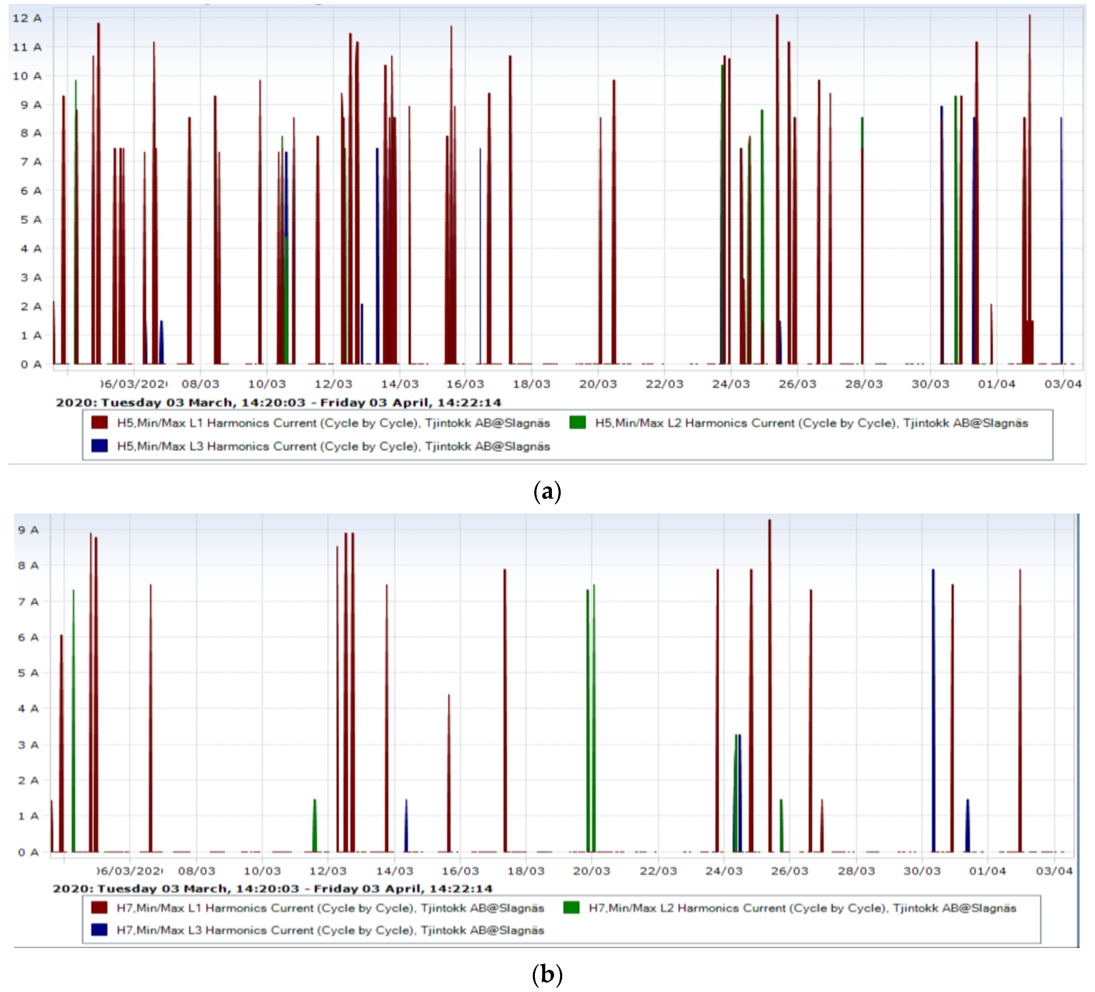
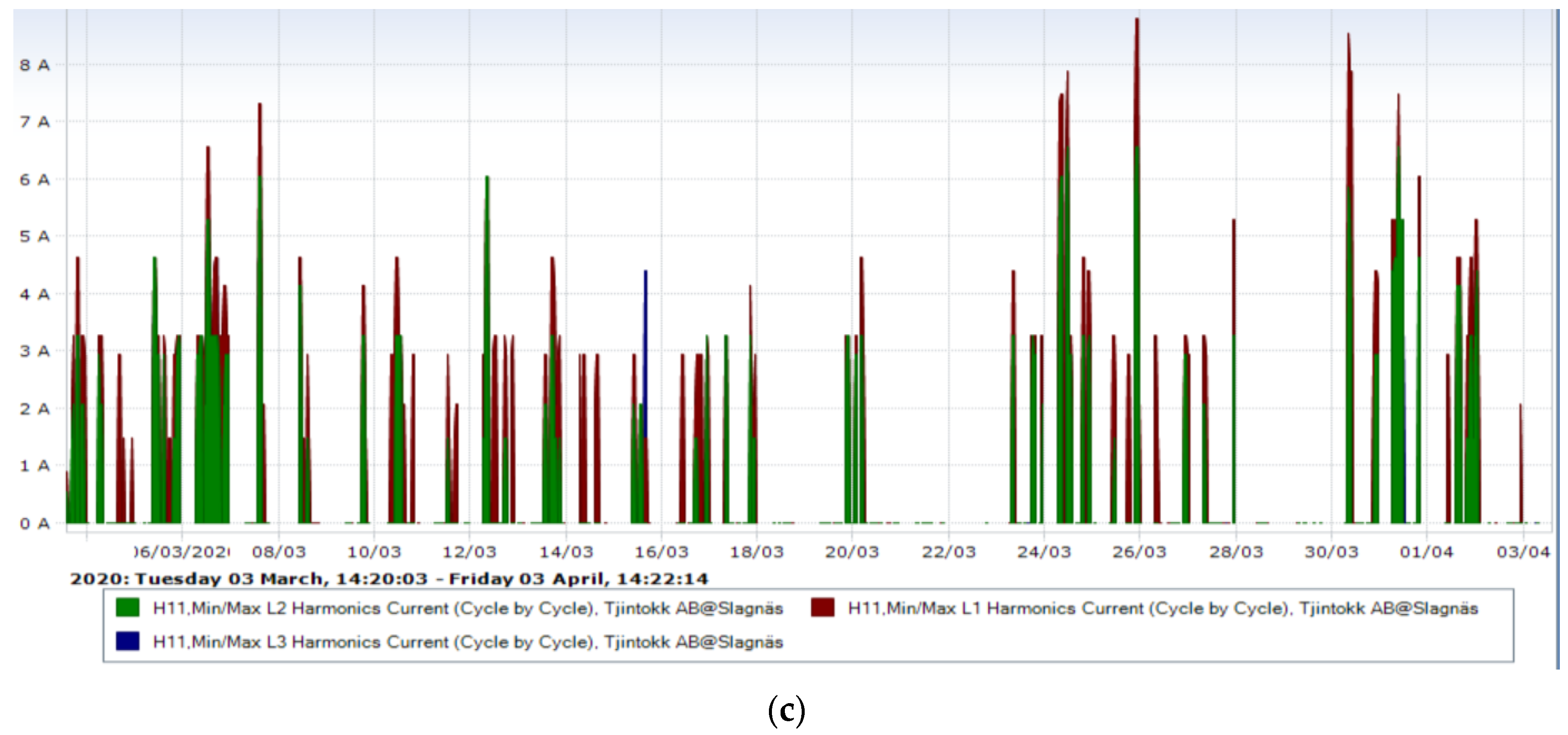
Figure 1. (a) 5th, (b) 7th, and (c) 11th harmonics of EV measurement at 160 kW charger.
From Figure 1, it can be noticed that almost all of the EVs generate significant 5th harmonic components, irrespective of the power electronic converter used. The summary of the lower-order harmonics as a box plot for the above-discussed case for a period of one month at a single charging outlet is shown in Figure 2.
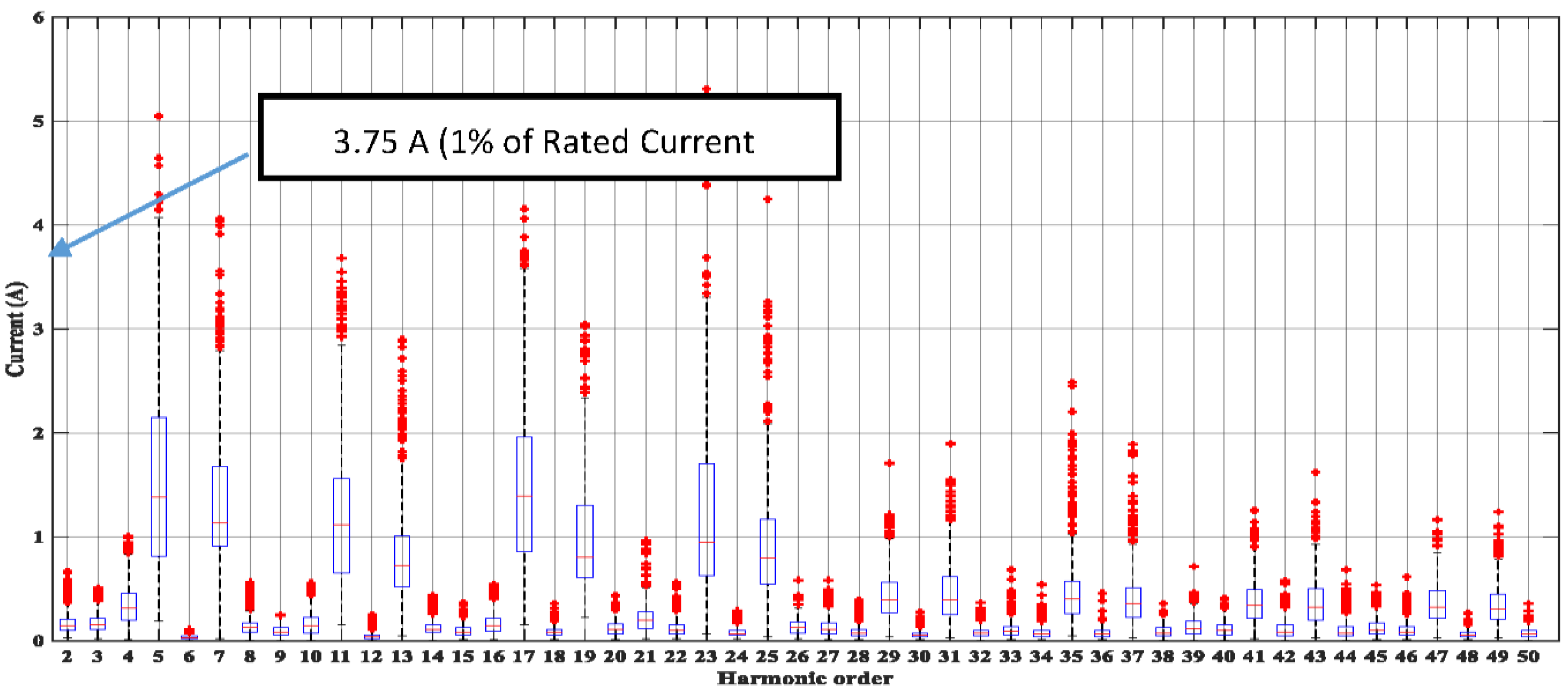
Figure 2. Box plot of lower-order harmonics of 160 kW charger [22].
Though the harmonic emissions are within the limit, higher harmonic values are possible when large numbers of charging stations are connected to transformers with many customers, due to harmonic aggregation. In Figure 2, high values of even harmonics (4th, 200 Hz) are also noticed, which may be due to frequency aggregation or direct currents. Taking into account the calculation of total harmonic current in the LV network, article [23] emphasizes the need for phase angle determination of the harmonic current to study the harmonic cancellation effect. When new power electronic components, such as the converters of EVs and LEDs, are slowly integrated to the grid, a better THD evaluation technique needs to be introduced in the standards. As the first step, the article identified the phase angles of the 3rd and 5th harmonics as 195° and 330°, respectively.
Traditionally, many researches focused on the issue of harmonic elimination due to EV chargers. The research article [24] investigated the EV coordination technique to eliminate current harmonic distortion, however, this solution also faced the trade-off between the interests of network operator and customers. To avoid any customer inconvenience posed by the utility fees and schedule, promising harmonic mitigation approaches move towards the use of active filters in smart appliances, such as PV inverters. The use of PV installation can offer the double benefit of charging the EVs and filtering the harmonics. In [25], an active filter solution was proposed to resolve harmonic issues. The study case considered an LV network supplied by a 250 kVA transformer, with five 215 kW EV fast charging stations and a 50 kW PV installation. In that scenario, the use of an active filter decreased the voltage THD from 11.4% to 5.6%, keeping the THD below the standard limit of 8%.
2.5. Interharmonics
Interharmonics are frequency components (below 2 kHz) that are not an integer multiple of the power-system frequency.
Their propagation through the grid is similar to the propagation of (normal, integer) harmonics: they have during-charging levels depending on pre-charging levels, emitted currents, and source impedance. There are, however, two important differences:
Pre-charging levels of interharmonics are typically low; the during-charging levels, therefore, depend mainly on the emitted current and source impedance. A consequence of this is that the phase angle of the interharmonic current, in most cases, does not matter for the resulting magnitude of the interharmonic voltage.
The three-phase EV charging RMS current and 10/12 spectrum of interharmonics current at a 175 kW, 360 A fast charging station are shown in Figure 3.
Figure 3. RMS current and 10/12-cycle values of interharmonic components in EV current measurements.
Interharmonics are mainly associated with the transients in the charging current. From grouping of interharmonics 0.5 (IH0), 3.5 (IH3), and 11.5 (IH11), it is inferred that the interharmonic component is higher during the transients at the start or end of fast charging. A higher value of interharmonics at 0.5 (IH0) grouping is observed because it includes the DC component also. Limited information is available in the literature on interharmonic currents emitted by EV charging.
2.6. Supraharmonic
Supraharmonics are defined by the frequency components in the range between 2 kHz and 150 kHz. In the modern grid, with penetration of renewable energy sources, EV, and many other components with power electronic converters, a new high-frequency component of distortion is observed in the grid at both the distribution and transmission side. The research of such high-frequency components is a relatively new field of study [26][27]. Hence, standardization of supraharmonic limits in the grid, and immunity limits for the equipment that produce it, is an urgent need. A recent study on propagation of supraharmonics in the medium-voltage network with 8 feeders reveals that the bigger the network, the more resonant frequencies are observed, whereas the amplitude of the resonant peak of the driving point impedance decreases. The aggregation of supraharmonics generated by multiple devices can get amplified by resonance and may cross the limit of 2% of nominal voltage set by the EN 50065 and IEC 61000-3-8 standards [28][29]. These standards are defined for 3 and 9 kHz frequencies only [30].
Emission of supraharmonic currents is observed with several measurements of the EV charging current. Supraharmonic voltages and changes compared to existing levels of supraharmonic voltages can thus be expected with EV charging.
A 6.6 kW EV charger measurement at Luleå Tekniska Universitet (LTU), Sweden, found the presence of supraharmonic emissions in the broadband range of 43 to 58 kHz, as shown in Figure 4.
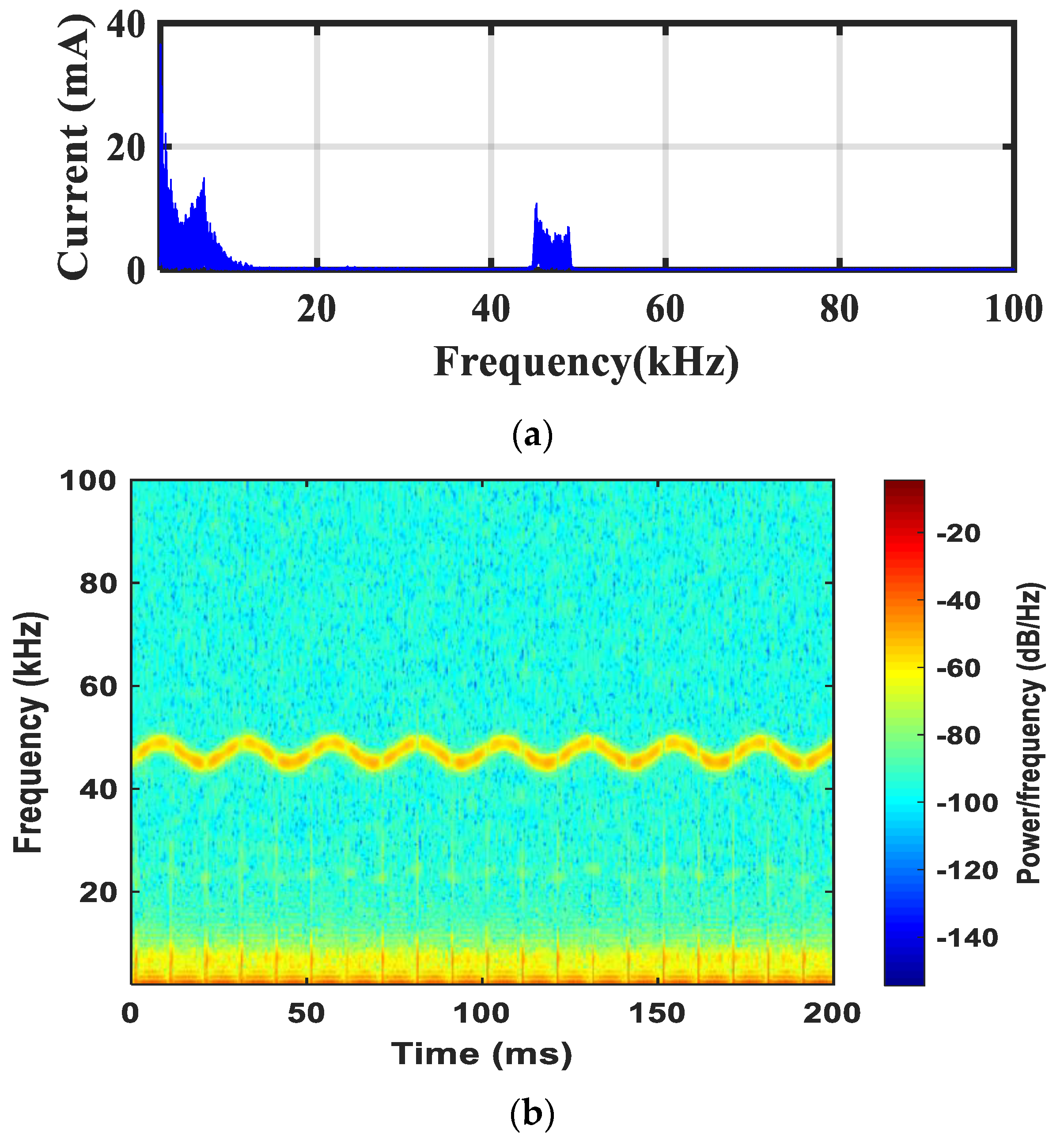
Figure 4. Supraharmonic emission due to EV charging. (a) Spectrum; (b) Spectrogram.
The supraharmonic emissions from EV may propagate through the protective earth. High magnitudes of the supraharmonic current through the protective earth, or leakage current beyond the installation, may result in tripping of residual current devices [31]. If the grid is weak, then the supraharmonic component may flow towards the grid and cause high supraharmonic voltages elsewhere [30].
2.7. Fast Voltage Variations
In the case of EV charging, the magnitude of fast voltage fluctuations depends on the transient charging current peak and impedance of the grid. The current peak depends on the state of the charge (SOC) of the EV. The SOC depends on the ambient temperature and on the battery’s age and capacity. A rapid voltage change is noticed during the start and end of the charging cycle, apart from the regular voltage checks done by the charging control circuit. This rapid voltage changes could create a light flicker (repetitive change in light intensity) that humans can perceive.
The charging signatures of vehicles A, B, and C are given in [32]. The battery status check of vehicle A, brief period charging breaks of Vehicle B, and rapid voltage charge of vehicle C, until it is unplugged, are discussed in [32].
During EV charging, the diagnosis and monitoring processes cause rapid voltage fluctuation [33].
The impact of those rapid voltage changes is light flicker; though not continuous, they result in temporary blinks in the light. When the blinks occur repetitively, this can be perceived as annoying, too.
2.8. Light Flicker
The root cause for light flicker is identified as the periodic amplitude modulation of the voltage waveform envelope, caused due to loads such as EV charging, ON/OFF of motor, switching of capacitor banks, etc. The voltage variation may include RMS dips, interharmonics, amplitude modulation, and notches. Very few researcher articles have addressed the issue of light flicker due to EV charging [22][32][34].
The flicker is calculated by a statistical process over a 10 min internal of voltage data, which is represented by Pst. A Pst > 1 indicates irritating flicker for a 60-watt incandescent lamp, as per the IEEE 1453 standard [35]. The flicker limits, with respect to the EV fleet, also depends on the background flicker due to other grid connected installations. In [34], light flicker on grids of different strength levels, based on short-circuit level and impedance angle, are analyzed. The study considered an Irish Atlantic Marine Energy Test site where an EV fleet was connected to the 20 kV bus. The analysis was done based on grid operator perspective, to maintain the voltage within the ±10% of the nominal voltage. Ten group of EVs were considered, in which each group created a 0.01 pu voltage deviation. The result shows a minimum short-circuit ratio of 19 for the impedance angle of 30, corresponding to the stringent limit of Pstmax = 0.3, for 5 groups of the EV fleet, connected. One of the disadvantages of this study was that it considered several groups of EV fleet getting connected to the grid with constant power, which might not be the scenario in reality.
Light flicker is a subject that has a direct impact on the customer, and is probably, therefore, one of the most commonly reported power-quality problems. The lighting industry and power-quality researchers are still struggling to establish links to characterize the temporal light flicker problems. Further studies are needed to find at least an explanation for the high number of reported cases.
2.9. Local Thermal Overload
In future, it is anticipated that more EVs will be charged residentially. Hence, safety precautions need to be taken against overloading and fire. In general, home wiring will not be able to continuously cater to 16 A/32 A for single-phase/three-phase charging, and may get heated up. Hence, it is advisable to a have separate connection for EV charging, with the socket outlet of the supply installed at least 2.6 feet above the ground level. Regardless of the sanctioned load, an earth leakage protection device needs to be installed.
2.10. Overloading of Cables, Lines, and Transformers
The large penetration of renewable energy sources and electric vehicles into the grid creates new challenges to the life of cables, transformers, and lines. Transformer and cable end-of-life failure is more dependent on the deterioration of the insulation, with respect to the temperature factor. In case of line failure, it is the loading factor [36].
The transformer is a major component whose life will be affected. In [37], a transformer thermal model has been developed which estimates the aging of a 25 kVA overhead distribution transformer servicing 12 homes, based on the IEEE C57.91-1995 standards [38]. The weakest link, which determines the transformer aging, is its internal insulation failure. With respect to the loading and temperature condition, an accelerated loading test was carried out to estimate the transformer’s life. The results show that the temperature-based smart coordinated charging of an AC Level 2 charger can reduce transformer’s life by a factor of 9.79 to 0.9 in Phoenix, Arizona. A study on transformer end-of-life estimation, based on the Arrhenius-Weibull distribution model, shows that, for a 200% EV penetration, the failure probabilities of a substation transformer is 13.2%, and that of line failure is 1.4% [36].
The impact of EV charging on the 7.5 kW North American Distribution System model was studied by the investigators in [39]. In article [39], the transformer’s loss-of-life (LoL) and the aging factor for 4 different scenarios of EV charging were studied, and the impact of EV charging was qualified using the IEEE Standard C57.91-2011. Four different scenarios were considered: (i) level 1 charger; (ii) 50% of level 1 and level 2; (iii) level 2; (iv) 40% level 1 overlapped with peak residential load. Considering the 4 scenarios, the transformer life was predicted, and it was observed that the life decreased by 10-, 14-, 66-, and 22-times the baseline load for an increased EV penetration. A local reactive power compensation technique was used to improve the transformer’s life by 49%, compared to the uncompensated technique.
Considering all the above factors, it can be concluded that the risk of overloading depends on the preloaded condition of the grid and the actual hosting capacity of the grid. For EV penetration into the grid, the transformers, line, and cables are more vulnerable to failures [36].
2.11. Overload Due to Fast Charging
Modern rapid chargers can charge at a very fast rate, with a power rating up to 350 kW. Such fast chargers will draw a huge current, up to 1250 A, during a very short period of time. Table 2 gives the electrical characteristics of slow and fast chargers.
Table 2. Charging power and time for some commercial electric vehicles [40].
| Charging Type | Type 1 J1772 (Slow) |
Type 2 (Fast) |
Type 2 (Fast) |
Type 2 (Fast) |
Type 2 IEC62196 (Fast) |
CHAdeMO (Rapid) |
|---|---|---|---|---|---|---|
| Electrical Parameters | 1Ф | 3Ф | 1Ф | 3Ф | 3Ф | Dc |
| 120/240 V | 400 V | 240 V | 400 V | 400 V | 50–700 V | |
| 16 A | 16 A | 32 A | 32 A | 63 A | 100–1250 A | |
| 3.3 kW | 10 kW | 7 kW | 24 kW | 43 kW | 50–350 kW | |
| Charging Time | 6–8 h | 2–3 h | 3–4 h | 1–2 h | 20–30 min | <20 min |
| Site | Residential area | Residential area | Public place | Bus stations/expressways | ||
Fast chargers are a concern in rural areas with weak grid impedance, where the distribution transformers may easily get overloaded.
For conductive charging of both AC and DC up to 1000 A AC and 1500 A DC, the IS 12360/IEC 60038 standard [41][42] requirements are followed. The CCS, CHAdeMO, and Type 2 AC fast chargers are the most common fast charging connectors used internationally. Some of the minimum requirements while installing such fast chargers that need to be considered are: (i) an exclusive transformer with all substation equipment related to the rating of the fast charger, including safety appliances; (ii) 33/11 kV line/cables with associated equipment, such as line termination, metering, digital communication equipment, etc. [43].
The different power quality (PQ) impacts discussed above cause peculiar operation of electrical devices, which cause heavy economic loss to both local customers and network operators. Since, with each power quality phenomenon, the indictors for ranking, such as severity with respect to magnitude, duration of the impact, fault clearing time, economic aspect, etc., varies, the quantification of losses is very complex. With a conventional outlook, it is expected that, in urban areas, overloading will be the major issue and, in rural areas, undervoltage will be the concern for network failure.
As per the Leonardo Power Quality Initiative (LPQI) survey in Europe and the Electric Power Research Institute (EPRI) survey in the United States, voltage sag and interruptions are the most common PQ problems, covering 55% and 48% of problems, respectively. On the other hand, the harmonics’ share is 5% in Europe and 22% in the US. In Australia, the distribution voltage is at a higher level; hence, overvoltage is a common PQ issue which results in premature aging of equipment. Hence, the ranking of the PQ impacts varies among different countries.
References
- Mohamed, S.E.; Magdy, M.A.S. A comprehensive study of the impacts of PHEVs on residential distribution networks. IEEE Trans. Sustain. Energy 2014, 5, 332–342.
- Sortomme, E.; Hindi, M.M.; MacPherson, S.D.J.; Venkata, S.S. Coordinated charging of plug-in hybrid electric vehicles to minimize distribution system losses. IEEE Trans. Smart Grid 2011, 2, 186–193.
- Deilami, S.; Masoum, A.S.; Moses, P.S.; Masoum, M.A.S. Real-time coordination of plug-in electric vehicle charging in smart grids to minimize power losses and improve voltage profile. IEEE Trans. Smart Grid 2011, 2, 456–467.
- Richardson, P.; Flynn, D.; Keane, A. Local versus centralized charging strategies for electric vehicles in low voltage distribution systems. IEEE Trans. Smart Grid 2012, 3, 1020–1028.
- Bollen, M.H.J.; Häger, M. Power quality: Interactions between distributed energy resources, the grid, and other customers. In Proceedings of the 1st International Conference on Renewable Energy Sources and Distributed Energy Resources, Brussels, Belgium, 1–3 December 2004.
- Letha, S.S.; Busatto, T.; Bollen, M.H.J. Interaction between Charging Infrastructure and the Electricity Grid: The Situation and Challenges Regarding the Influence of Electromobility on Mainly Low Voltage Networks; Luleå University of Technology: Luleå, Sweden, 2021; ISBN 978-91-7790-807-4.
- IEC 60364-5-52:2009; Low-voltage electrical installations—Part 5-52: Selection and erection of electrical equipment—Wiring systems. International Electrotechnical Commission: Geneva, Switzerland, 2009.
- Behravesh, V.; Keypour, R.; Akbari Foroud, A. Control strategy for improving voltage quality in residential power distribution network consisting of roof-top photovoltaic-wind hybrid systems, battery storage and electric vehicles. Sol. Energy 2019, 182, 80–95.
- Leemput, N.; Frederik Geth, F.; Roy, J.V.; Büscher, J.; Driesen, J. Reactive power support in residential LV distribution grids through electric vehicle charging. Sustain. Energy Grids Netw. 2015, 3, 24–35.
- Fuentes, E.V.; Deniz, F.; Martínez, A.V. Electric vehicle grid integration analysis in low voltage networks—A case study. Int. Conf. Mod. Electr. Power Eng. 2016, 1, 85–88.
- Bollen, M.H.J. Överspänning Från Enfasanslutna Solpaneler; Energiforsk Report 506; Energiforsk/Luleå Tekniska Universitet: Luleå, Sweden, 2018.
- Bollen, M.H.J.; Rönnberg, S.K.; Lennerhag, O. Påverkan på Nätet av Stora Mängder Solkraft; Energiforsk Rapport 539; Energiforsk/Luleå Tekniska Universitet: Luleå, Sweden, 2018. (In Swedish)
- Kundu, S.; Hiskens, I.A. Overvoltages due to Synchronous Tripping of Plug-in Electric-Vehicle Chargers Following Voltage Dips. IEEE Trans. Power Deliv. 2014, 29, 1147–1156.
- SAE International. Power quality requirements for plug-in electric vehicle chargers. In Surface Vehicle Recommended Practice J2894–1; SAE International: Warrendale, PA, USA, 2011.
- EN 50160; Voltage Characteristics of Electricity Supplied by Public Distribution Systems. Wroclaw University of Technology: Wroclaw, Poland, 2007.
- Ul-Haq, A.; Cecati, C.; Strunz, K.; Abbasi, E. Impact of Electric Vehicle Charging on Voltage Unbalance in an Urban Distribution Network. Intell. Ind. Syst. 2015, 1, 51–60.
- Panich, S.; Singh, J.G. Impact of plug-in electric vehicles on voltage unbalance in distribution systems. Int. J. Eng. Sci. Technol. 2015, 7, 76–93.
- Shahnia, F.; Ghosh, A.; Ledwich, G.; Zare, F. Predicting Voltage Unbalance Impacts of Plug-in Electric Vehicles penetration in residential low-voltage distribution networks. Electr. Power Compon. Syst. 2013, 41, 1594–1616.
- Helm, S.; Hauer, I.; Wolter, M.; Wenge, C.; Balischewski, S.; Komarnicki, P. Impact of unbalanced electric vehicle charging on low-voltage grids. In Proceedings of the IEEE PES Innovative Smart Grid Technologies Europe (ISGT-Europe), The Hague, The Netherlands, 26–28 October 2020; pp. 665–669.
- Gómez, J.C.; Morcos, M.M. Impact of EV Battery Chargers on the Power Quality of Distribution Systems. IEEE Trans. Power Deliv. 2003, 18, 975–981.
- Zhang, Y.; Yu, D.; Zhang, G.; Wang, H.; Zhuang, J. Harmonic Analysis of EV Charging Station Based on Measured Data. In Proceedings of the IEEE/IAS Industrial and Commercial Power System Asia, Weihai, China (I&CPS Asia), Weihai, China,, 13–15 July 2020; pp. 475–480.
- Letha, S.S.; Bollen, M.H.J. Impact of Electric Vehicle Charging on The Power Grid; Luleå University of Technology: Luleå, Sweden, 2021; ISBN 978-91-7790-763-3.
- Meyer, J.; Blanco, A.; Domagk, M.; Schegner, P. Assessment of prevailing harmonic current emission in public low-voltage networks. IEEE Trans. Power Deliv. 2017, 32, 962–970.
- Deilami, S.; Masoum, A.S.; Moses, P.S.; Masoum, M.A.S. Voltage profile and THD distortion of residential network with high penetration of plug-in electrical vehicles. In Proceedings of the 2010 IEEE PES Innovative Smart Grid Technologies Conference Europe (ISGT Europe), Gothenberg, Sweden, 11–13 October 2010; pp. 1–6.
- Nguyen, V.L.; Tran-Quoc, T.; Bacha, S. Harmonic distortion mitigation for electric vehicle fast charging systems. In Proceedings of the 2013 IEEE Grenoble Conference, Grenoble, France, 16–20 June 2013; pp. 1–6.
- Rönnberg, S.K.; Bollen, M.H.J. Propagation of Supraharmonics in the Low-Voltage Grid; Energiforsk Rapport 461; Energiforsk/Luleå Tekniska Universitet: Luleå, Sweden, 2017. (In Swedish)
- Rönnberg, S.K.; Bollen, M.H.J.; Amaris, H.; Chang, G.W.; Gu, I.Y.H.; Kocewiak, Ł.H.; Meyer, J.; Olofsson, M.; Ribeiro, P.; Desmet, J. On waveform distortion in the frequency range of 2 kHz–150 kHz—Review and research challenges. Electr. Pow. Syst. Res. 2017, 150, 1–10.
- EN 50065; Signalling on low-voltage electrical installations in the frequency range 3 kHz to 148,5 kHz - Part 1: General requirements, frequency bands and electromagnetic disturbances. European Standard: Brussels, Belgium, 2011.
- IEC 61000-3-8:1997; Electromagnetic compatibility (EMC)—Part 3: Limits—Section 8: Signalling on low-voltage electrical installations—Emission levels, frequency bands and electromagnetic disturbance levels. International Electrotechnical Commission: Geneva, Switzerland, 1997.
- Letha, S.S.; Delgado, A.E.; Rönnberg, S.K.; Bollen, M.H.J. Evaluation of Medium Voltage Network for Propagation of Supraharmonics Resonance. Energies 2021, 14, 1093.
- Sutaria, J.; Ahmed, K.; Rönnberg, S.K.; Bollen, M.H.J. Propagation of supraharmonics through EMI filters with varying loads. In Proceedings of the 2019 Nordic Workshop on Power and Industrial Electronics (NORPIE), Narvik, Norway, 25–27 September 2019.
- Seljeseth, H.; Taxt, H.; Solvang, T. Measurements of network impact from electric vehicles during slow and fast charging. In Proceedings of the 22nd International Conference and Exhibition on Electricity Distribution (CIRED 2013), Stockholm, Sweden, 10–13 June 2013; pp. 1–4.
- IEEE Std 2030.1.1-2015; IEEE Standard Technical Specifications of a DC Quick Charger for Use with Electric Vehicles. IEEE Vehicular Technology Society: Piscataway, NJ, USA, 2015.
- Blavette, A.; Le Goff Latimier, R.; Ahmed, H.B.; Multon, B. Analysis of the flicker level generated by the grid-connection of a fleet of electric vehicles. In Proceedings of the 2016 IEEE PES Innovative Smart Grid Technologies Conference Europe (ISGT-Europe), Ljubljana, Slovenia, 9–12 October 2016; pp. 1–6.
- IEEE 1453-2022; IEEE Standard for Measurement and Limits of Voltage Fluctuations and Associated Light Flicker on AC Power Systems. IEEE Power and Energy Society: Piscataway, NJ, USA, 2022.
- Zhao, J.; Arefi, A.; Borghetti, A. End-of-life Failure Probability Assessment Considering Electric Vehicle Integration. In Proceedings of the 2021 31st Australasian Universities Power Engineering Conference (AUPEC), Perth, Australia, 26–30 September 2021; pp. 1–6.
- Hilshey, A.D.; Hines, P.D.H.; Rezaei, P.; Dowds, J.R. Estimating the Impact of Electric Vehicle Smart Charging on Distribution Transformer Aging. IEEE Trans. Smart Grid 2013, 4, 905–913.
- IEEE C57.91-1995; IEEE Guide for Loading Mineral-Oil-Immersed Transformers. IEEE Power and Energy Society: Piscataway, NJ, USA, 1995.
- Jain, A.; Karimi-Ghartemani, M. Mitigating Adverse Impacts of Increased Electric Vehicle Charging on Distribution Transformers. Energies 2022, 15, 9023.
- Atmaja, T.D.; Amin. Energy Storage System Using Battery and Ultracapacitor on Mobile Charging Station for Electric Vehicle. Energy Procedia 2015, 68, 429–437, ISSN 1876-6102.
- IS 12360; Voltage Bands for Electrical Installations Including Preferred Voltage and Frequency. Bureau of Indian Standards: New Delhi, India, 1998.
- IEC 60038:2009; IEC standard voltages. International Electrotechnical Commission: Geneva, Switzerland, 2009.
- Amitabh, K.; Randheer, S.; Sanjeev, K.K.; Ashutosh, S.; Sajid, M.; Abhishek, S.; Chaitanya, K.; Shyamasis, D.; Pawan, M. Handbook of Electric Vehicle Charging Infrastructure Implementation, Version-1. In Handbook of NITI Aayog, MoP, DST, BEE, and WRI India; NITI Aayog: New Delhi, India, 2021.
More
Information
Subjects:
Engineering, Electrical & Electronic
Contributors
MDPI registered users' name will be linked to their SciProfiles pages. To register with us, please refer to https://encyclopedia.pub/register
:
View Times:
2.1K
Revisions:
2 times
(View History)
Update Date:
28 Jun 2023
Table of Contents


Notice
You are not a member of the advisory board for this topic. If you want to update advisory board member profile, please contact office@encyclopedia.pub.
OK
Confirm
Only members of the Encyclopedia advisory board for this topic are allowed to note entries. Would you like to become an advisory board member of the Encyclopedia?
Yes
No
${ textCharacter }/${ maxCharacter }
Submit
Cancel
Back
Comments
${ item }
|
${ item.createdUser.fullName }
${ item.createdAt }
${ item.vote }
${ item.reply }
Delete
${ reply.createdUser.fullName }
${ reply.createdAt }
${ reply.vote }
Delete
There is no reply to this comment~
${ item.replyTextCharacter }/${ item.replyMaxCharacter }
Submit
Cancel
More
No more~
There is no comment~
${ textCharacter }/${ maxCharacter }
Submit
Cancel
${ selectedItem.replyTextCharacter }/${ selectedItem.replyMaxCharacter }
Submit
Cancel
Confirm
Are you sure to Delete?
Yes
No