Your browser does not fully support modern features. Please upgrade for a smoother experience.
Submitted Successfully!
 +1 credit
Thank you for your contribution! You can also upload a video entry or images related to this topic.
For video creation, please contact our Academic Video Service.
Video Upload Options
We provide professional Academic Video Service to translate complex research into visually appealing presentations. Would you like to try it?
Cite
If you have any further questions, please contact Encyclopedia Editorial Office.
Li, M.; Huang, K.; Yi, X. Cracks Types and Causes of Laser Cladding Coatings. Encyclopedia. Available online: https://encyclopedia.pub/entry/46016 (accessed on 16 July 2026).
Li M, Huang K, Yi X. Cracks Types and Causes of Laser Cladding Coatings. Encyclopedia. Available at: https://encyclopedia.pub/entry/46016. Accessed July 16, 2026.
Li, Mingke, Kepeng Huang, Xuemei Yi. "Cracks Types and Causes of Laser Cladding Coatings" Encyclopedia, https://encyclopedia.pub/entry/46016 (accessed July 16, 2026).
Li, M., Huang, K., & Yi, X. (2023, June 26). Cracks Types and Causes of Laser Cladding Coatings. In Encyclopedia. https://encyclopedia.pub/entry/46016
Li, Mingke, et al. "Cracks Types and Causes of Laser Cladding Coatings." Encyclopedia. Web. 26 June, 2023.
Copy Citation
Laser cladding, a novel surface treatment technology, utilizes a high-energy laser beam to melt diverse alloy compositions and form a specialized alloy-cladding layer on the surface of the substrate to enhance its property. However, it can generate substantial residual stresses during the rapid cooling and heating stages, due to inadequate selection of cladding process parameters and disparities in thermophysical properties between the clad layer and substrate material, leading to the formation of various types of cracks. These cracks can significantly impact the quality and performance of the coating.
laser cladding coating
cracks
residual stress
causes
control methods
1. Introduction
Laser cladding (LC) is an advanced surface modification technology that utilizes a high-energy laser beam to melt the clad material, forming a strong metallurgical bond with the substrate material [1]. This technology offers numerous advantages, including high bond strength, minimal heat-affected zone, low thermal deformation, and low dilution rate [2][3][4]. It has found extensive applications in aerospace, automotive, and chemical industries, among others [5][6][7]. The LC system usually consists of a KUKA robot or robot arm, LC head, powder feeder, protective gas, water cooling system, and workbench [8] (Figure 1).
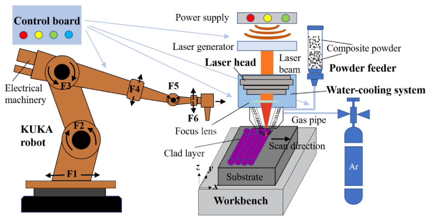
Figure 1. Schematic diagram of the laser cladding system.
Despite the excellent performance of laser melting coatings, the rapid melting and solidification process can give rise to defects such as cracks, porosity, and inclusions within the coating. Among these defects, cracks are the most common internal issue in the laser cladding process [9][10]. Microscopic cracks within the coating can propagate into macroscopic cracks under working loads, significantly compromising the coating’s quality [11]. Consequently, current research focuses on suppressing or eliminating internal cracks in laser cladding coatings, which presents a challenging and active area of study [12][13].
In recent years, scholars have conducted extensive experimental research on the causes and control methods of cracks in laser cladding coatings. Zhang et al. [14] and Galy et al. [15] reviewed the solidification theory of the selective laser melting (SLM) process and the formation mechanisms of the hole and crack defects. Quazi et al. [16] discussed the influence of rare earth additives on the crack sensitivity of coatings. Similarly, Wang et al. [17] and Hu et al. [18] suggested improvement strategies, including optimizing process parameters and employing preheating treatments, to mitigate coating cracks. The formation of cracks in laser cladding coatings is primarily attributed to residual stresses. While existing equipment can measure residual stress, the process is intricate, challenging, and costly. To overcome this limitation, scholars have conducted relevant studies using numerical simulations. Fang et al. [19] reviewed physical models of residual stresses for defects in selective laser melting (SLM) and machined parts, analyzed the advantages and disadvantages of mainstream models, and proposed conceptual methods to enhance residual stress management. Sanaei et al. [20] discussed characterization methods and statistical analysis of coating defects in additive manufacturing (AM), summarizing the effects of process parameters and post-processing on defects. Cheng et al. [21] reviewed the simulation techniques for grain growth mechanism, temperature, and stress distribution in the melt pool directly related to defect formation in the laser metal deposition (LMD) technique. Additionally, the defect suppression methods and the performance improvement methods of filled layers in LMD technology are presented.
2. Types and Causes of Cracks
2.1. Types of Cracks
Laser-clad coatings exhibit various types of cracks, which can be attributed to the selection of different cladding materials and process parameters. To effectively address the cracking issue in laser-clad coatings, it is crucial to identify the types of coating cracks and understand their causes. To address the issue of the types of cracks in laser-clad coatings, they can be classified as hot and cold cracks according to the time, temperature, and fracture characteristics of the coating cracks, and most of the coating cracks are cold cracks [22].
Hot cracks mainly occur above the solidification temperature line, and their sections have a distinct oxidation color and no metallic luster (Figure 2a). For example, most of the common types of cracks in melt layers, such as austenitic stainless steels, are hot cracks [23]. Hot cracks sprout from hot tearing and are easily influenced by microstructure [24]. Partition of low melting point elements such as Si and C in the molten layer [25][26], inhomogeneous distribution of coarse and brittle phases of compounds and impurities [27], and disordered grain growth are the main factors for the formation of hot cracks [28]. This is due to the fact that the liquid metal in the melt pool has a very high temperature, so the liquid metal is componentlessly subcooled at the beginning of solidification, and therefore large tensile stresses are formed at the coarse eutectic tissue at low melting points. The tensile stress pulls the solidified tissue partially along the grain boundary, resulting in not enough liquid phase to fill the tissue gap, thus producing cracks. Therefore, thermal-type cracks mostly show cracking characteristics along the grain [29].
Cold cracks mainly occur below the solidification temperature line, and the fractured section of cold cracks appears relatively smooth with a metallic luster (Figure 2b). Cold cracks often involve secondary crack generation, indicating a brittle fracture behavior. For instance, nickel-based alloy powder coatings commonly exhibit cold cracks [30]. Improper selection of melting process parameters and excessive thermal gradients in the melt pool are the main factors contributing to cold crack formation. This is due to the susceptibility of martensitic phase transformation at the solidification temperature line [31], leading to the hardening of the coating. The differences in thermal–physical parameters between the cladding material and the substrate material, coupled with the cooling and solidification process, result in the generation of large residual thermal stresses. When these residual thermal stresses surpass the tensile strength limit of the material, cold cracks occur [31][32][33]. Consequently, cold cracks typically exhibit crack propagation through the crystal structure [34].

Figure 2. Different types of crack morphology. (a) The hot cracks in HSLA powder samples (the laser power is 2900 W and the scan speed is 10 mm/s) [25]; (b) the cold cracks in Ni-Cu alloy sample (the laser power is 5000 W and the scan speed is 30 mm/s) [35]; (c) cladding layer crack in ZhS32 alloy (the laser power is 600 W and the scan speed is 9 mm/s) [36]; (d) interface substrate crack in nickel-based K477A (the laser power is 576 W and the scan speed is 4 mm/s) [37]; (e) overlap zone crack in Ni60 (the laser power is 3200 W and the scan speed is 416.7 mm/s) [38].
Depending on their location, coating cracks can be classified as fusion layer cracks, interface substrate cracks, and overlap zone cracks [37][38][39].
Cladding layer crack is caused by rapid cooling during the solidification process, leading to significant thermal stress. Uneven stress distribution resulting from the uneven mixing of cladding material or the presence of impurities can also contribute to the cracking of the cladding layer (Figure 2c). When cracks form within the clad layer, they often initiate near hard-phase particles and propagate vertically through the coating. In some cases, the cracks even extend into the substrate. When cracks reach the surface, they exhibit a “herringbone” or lattice-like pattern [34][39].
Interface substrate crack primarily arises from the excessive difference in thermal expansion coefficient and Young’s modulus between the substrate and the molten cladding layer. This difference creates thermal stresses under large temperature gradients during solidification and cooling. Additionally, the molten metal liquid experiences restraint stress from the substrate during thermal expansion and cooling contraction. As a result of the combined effects of thermal and restraint stresses, cracking occurs at the interface between the clad layer and the substrate, gradually propagating to the surface of the molten cladding layer (Figure 2d) [37], forming interface substrate cracks.
Overlap zone cracks predominantly occur in the lap zone as a result of an unreasonable selection of the overlap rate. This leads to the accumulation of heat, an increase in temperature gradient, and elevated thermal stress. Consequently, the grain growth time is prolonged, resulting in coarser grains, as well as the formation of pores or impurities. The expansion of these defects eventually leads to the development of lap zone cracks (Figure 2e). Moreover, the low yield strength and tensile rate of the clad material make it more susceptible to cracking and expansion under combined stress. Consequently, overlap zone cracks tend to propagate throughout the entire fusion cladding layer once they form [40][41].
In summary, hot cracks are mainly caused by hot tearing and are significantly influenced by the microstructure of the coating. The presence of coarse brittle phases and impurities in the molten clad layer, along with thermal cycling and stress concentration due to the shaped orientation of grain boundaries, are the key factors contributing to the formation of hot cracks. Cold cracks, on the other hand, are mainly a consequence of improper selection of process parameters and excessive temperature gradients, resulting in brittle fractures due to tensile stresses exceeding the tensile strength of the molten material. Cracks in the cladding layer arise from the uneven distribution of coating tissue and a substantial difference in the thermal expansion coefficient of the cladding layer. Interface substrate cracks primarily occur due to the excessive temperature gradient between the substrate and the clad layer. Overlap zone cracks, finally, are predominantly caused by inappropriate overlap rate selection. These different types of coating cracks can be analyzed based on their causes of formation, with the strain generated during the melting process being greater than the plastic strain of the molten layer itself, serving as the fundamental cause of coating cracks.
2.2. Causes of Cracks
The laser cladding process is very complex, and the coating generates significant stresses during the cladding and cooling process. When the stresses in the coating exceed the yield limit of the coating material, they can lead to cracking of the coating. The formation of cracks in laser-clad coatings can be attributed to the presence of residual stresses, which can be categorized into three primary types: thermal stresses, organizational stresses, and restraint stresses (Figure 3) [42][43][44].

Figure 3. Schematic of principle of three different stress: (a) thermal stress; (b) organizational stress; and (c) restraint stress.
2.2.1. Thermal Stress
The presence of thermal stress in laser-clad coatings can be attributed to the disparate modulus of elasticity and coefficient of thermal expansion between the substrate and the clad material. This results in varying rates of thermal expansion and cooling contraction within the clad layer. When a temperature gradient exists, the clad layer experiences stress, known as thermal stress (Figure 3a) [45]. If the thermal stress surpasses the material’s yield limit, it can give rise to cracks in the coating. The calculation of thermal stress involves determining the extent of the stress [45].
E is the elastic modulus of the cladding material, Δ𝛼Δ is the difference in thermal expansion coefficient between the cladding layer and substrate material, Δ𝑇Δ is the difference between cladding temperature and room temperature, and v is Poisson’s ratio of the cladding layer.
The relationship expressed in Equation (1) reveals that the Poisson’s ratio of the molten layer decreases as the thermal expansion coefficient difference between the molten layer and the substrate material increases. Consequently, a larger temperature difference leads to greater thermal stress, making the coating more susceptible to cracking [46]. Because the substrate is difficult to replace in the selection process, and the coefficient of thermal expansion and Young’s modulus of the cladding material also differ greatly, the selection of cladding material is particularly important. For instance, when the coating material consists of ceramic particles and the substrate is made of a metal alloy, the distinct thermophysical properties of these materials can cause cracking if the number of ceramic particles added is not carefully chosen. To address this issue, the composition of the cladding layer is commonly adjusted to alleviate the impact of thermal stress [47].
2.2.2. Organizational Stress
During the solidification and crystallization process of the liquid metal within the molten pool, a rearrangement of the physical phase structure takes place, resulting in the generation of internal stress known as organizational stress (Figure 3b) [48]. As thermal cycling progresses, the organizational stress accumulates until it reaches the yield strength of the material. This accumulation of stress can lead to tissue damage, the formation of microscopic defects, and even the development of microcracks, ultimately resulting in brittle fractures. Griffith introduced and refined a model that relates brittle fracture strength to material properties and damage [48], which can be expressed as follows:
E is the modulus of elasticity, 𝛾 is the material surface energy, 𝛾𝑝 is the microcracks or micro defects expanding the plastic work per unit length, 𝐶𝑧 is the size of the microcracks and micro defects.
The fracture surface energy 𝛾 is about , 𝑎 is the lattice distance of the crystal; the plastic work 𝛾𝑝 is 2~3 orders of magnitude larger than 𝛾.
The fracture strength of a material can be estimated by considering the size of the microcrack and the average lattice distance, although the specific value varies depending on the crystallographic system. For instance, in laser-fused coatings containing hard phases such as Cr7C3 and Cr23C6, when the size of the microdamage crack within the coating ranges from 3 to 5 μm, the calculated fracture strength (denoted as “𝜎𝑓”) is approximately 4.4 GPa [49]. When the stress in the coating exceeds this fracture strength, the microcrack extends and develops into macroscopic cracks. Hard phases are generally added to the coating to improve its performance, resulting in poor fluidity of the coating and uneven powder mixing. Therefore, the coating, after melting, is prone to elemental segregation. The presence of elemental segregation contributes to an inhomogeneous phase transition structure, resulting in stress concentration and elevated organizational stresses. Ramakrishnan et al. [50] proposed that Inconel 738 coating cracking occurs due to the micro-segregation of aluminum (Al) and titanium (Ti) elements, as well as the presence of low melting point crack boundaries.
The concept of micro-bias is directly associated with the diffusion coefficient of liquid alloying elements in the melt pool. This diffusion coefficient can be determined using Formula (3) [51].
K is the rate coefficient, E is the activation energy, T is the absolute temperature, A is the frequency factor, and R is the ideal gas law constant.
The relationship expressed in Formula (3) reveals that an increase in the cooling rate leads to a decrease in the diffusion coefficient of elements, resulting in reduced microscopic segregation and decreased crack sensitivity. To mitigate these effects and minimize organizational stress caused by uneven phase transformation, various approaches can be employed. These include implementing auxiliary fields, refining the size of the hard phase, or selecting appropriate process parameters. These measures help slow down elemental segregation and promote a more uniform phase distribution within the material.
2.2.3. Constraint Stress
During laser cladding, as the molten cladding layer undergoes heating and expansion or cooling and contraction, hindering stress arises from the un-melted portion on the melted part, referred to as restraint stress (Figure 3c) [52]. Two types of restraint stresses can be identified: the first is compressive stress resulting from the thermal expansion of the initially melted material in the melt pool, constrained by the colder surrounding substrate; the second is tensile stress generated as the molten liquid metal is held by other colder parts of the substrate during condensation and cooling shrinkage.
The constraint stress mainly comes from the constraints of the matrix, so the constraint stress at the edge of the cladding layer is relatively small and less prone to cracking. Research indicates that the middle section of the molten cladding layer is particularly susceptible to cracking due to heat accumulation and limited heat dissipation area, thus requiring additional constraints [53]. Appropriate heat treatment techniques can help reduce restraint stress [54]. In addition, the use of low transformation temperature (LTT) alloys can effectively reduce the accumulation of tensile stress. This is because the low transformation temperature alloy can use the expansion of martensite transformation to offset part or all of the heat shrinkage, thereby reducing the residual tensile stress [55]. However, it is important to note that the melting and cooling behavior of the laser cladding pool is highly complex, and residual stresses are challenging to eliminate entirely. The non-uniform distribution of temperature, stress, and flow fields within the melt pool exacerbates residual stresses, especially when there is a significant temperature gradient or a mismatch in the thermal expansion coefficient and elastic modulus between the molten material and the substrate. Consequently, regulating thermal stress, organizational stress, and restraint stress during the laser cladding coating process, minimizing the individual or interactive effects of these stresses, and preventing or eliminating coating cracking remain significant challenges in current research.
References
- Zhu, L.; Xue, P.; Lan, Q.; Meng, G.; Ren, Y.; Yang, Z.; Xu, P.; Liu, Z. Recent Research and Development Status of Laser Cladding: A Review. Opt. Laser Technol. 2021, 138, 106915.
- He, B.; Zhang, L.; Zhu, Q.; Wang, J.; Yun, X.; Luo, J.; Chen, Z. Effect of Solution Treated 316L Layer Fabricated by Laser Cladding on Wear and Corrosive Wear Resistance. Opt. Laser Technol. 2020, 121, 105788.
- Wang, Q.-Y.; Zhang, Y.-F.; Bai, S.-L.; Liu, Z.-D. Microstructures, Mechanical Properties and Corrosion Resistance of Hastelloy C22 Coating Produced by Laser Cladding. J. Alloys Compd. 2013, 553, 253–258.
- Lu, X.-L.; Liu, X.-B.; Yu, P.-C.; Qiao, S.-J.; Zhai, Y.-J.; Wang, M.-D.; Chen, Y.; Xu, D. Synthesis and Characterization of Ni60-HBN High Temperature Self-Lubricating Anti-Wear Composite Coatings on Ti6Al4V Alloy by Laser Cladding. Opt. Laser Technol. 2016, 78, 87–94.
- Wu, C.L.; Zhang, S.; Zhang, C.H.; Zhang, J.B.; Liu, Y.; Chen, J. Effects of SiC Content on Phase Evolution and Corrosion Behavior of SiC-Reinforced 316L Stainless Steel Matrix Composites by Laser Melting Deposition. Opt. Laser Technol. 2019, 115, 134–139.
- Zhang, P.; Liu, X.; Yan, H. Phase Composition, Microstructure Evolution and Wear Behavior of Ni-Mn-Si Coatings on Copper by Laser Cladding. Surf. Coat. Technol. 2017, 332, 504–510.
- Siddiqui, A.A.; Dubey, A.K. Recent Trends in Laser Cladding and Surface Alloying. Opt. Laser Technol. 2021, 134, 106619.
- Chen, L.; Yu, T.; Chen, X.; Zhao, Y.; Guan, C. Process Optimization, Microstructure and Microhardness of Coaxial Laser Cladding TiC Reinforced Ni-Based Composite Coatings. Opt. Laser Technol. 2022, 152, 108129.
- Lu, J.Z.; Xue, K.N.; Lu, H.F.; Xing, F.; Luo, K.Y. Laser Shock Wave-Induced Wear Property Improvement and Formation Mechanism of Laser Cladding Ni25 Coating on H13 Tool Steel. J. Mater. Process. Technol. 2021, 296, 117202.
- Guo, C.; Chen, J.; Zhou, J.; Zhao, J.; Wang, L.; Yu, Y.; Zhou, H. Effects of WC–Ni Content on Microstructure and Wear Resistance of Laser Cladding Ni-Based Alloys Coating. Surf. Coat. Technol. 2012, 206, 2064–2071.
- Song, J.; Deng, Q.; Chen, C.; Hu, D.; Li, Y. Rebuilding of Metal Components with Laser Cladding Forming. Appl. Surf. Sci. 2006, 252, 7934–7940.
- Lu, M.; McCormick, P.; Zhao, Y.; Fan, Z.; Huang, H. Laser Deposition of Compositionally Graded Titanium Oxide on Ti6Al4V Alloy. Ceram. Int. 2018, 44, 20851–20861.
- Lian, G.; Yao, M.; Zhang, Y.; Huang, X. Analysis and Respond Surface Methodology Modeling on Property and Performance of Two-Dimensional Gradient Material Laser Cladding on Die-Cutting Tool. Materials 2018, 11, 2052.
- Zhang, J.; Song, B.; Wei, Q.; Bourell, D.; Shi, Y. A Review of Selective Laser Melting of Aluminum Alloys: Processing, Microstructure, Property and Developing Trends. J. Mater. Sci. Technol. 2019, 35, 270–284.
- Galy, C.; Le Guen, E.; Lacoste, E.; Arvieu, C. Main Defects Observed in Aluminum Alloy Parts Produced by SLM: From Causes to Consequences. Addit. Manuf. 2018, 22, 165–175.
- Quazi, M.M.; Fazal, M.A.; Haseeb, A.S.M.A.; Yusof, F.; Masjuki, H.H.; Arslan, A. Effect of Rare Earth Elements and Their Oxides on Tribo-Mechanical Performance of Laser Claddings: A Review. J. Rare Earths 2016, 34, 549–564.
- Wang, X.; Lei, L.; Yu, H. A Review on Microstructural Features and Mechanical Properties of Wheels/Rails Cladded by Laser Cladding. Micromachines 2021, 12, 152.
- Hu, Y.; Cong, W. A Review on Laser Deposition-Additive Manufacturing of Ceramics and Ceramic Reinforced Metal Matrix Composites. Ceram. Int. 2018, 44, 20599–20612.
- Fang, Z.-C.; Wu, Z.-L.; Huang, C.-G.; Wu, C.-W. Review on Residual Stress in Selective Laser Melting Additive Manufacturing of Alloy Parts. Opt. Laser Technol. 2020, 129, 106283.
- Sanaei, N.; Fatemi, A. Defects in Additive Manufactured Metals and Their Effect on Fatigue Performance: A State-of-the-Art Review. Prog. Mater. Sci. 2021, 117, 100724.
- Cheng, J.; Xing, Y.; Dong, E.; Zhao, L.; Liu, H.; Chang, T.; Chen, M.; Wang, J.; Lu, J.; Wan, J. An Overview of Laser Metal Deposition for Cladding: Defect Formation Mechanisms, Defect Suppression Methods and Performance Improvements of Laser-Cladded Layers. Materials 2022, 15, 5522.
- Wang, F.; Mao, H.; Zhang, D.; Zhao, X.; Shen, Y. Online Study of Cracks during Laser Cladding Process Based on Acoustic Emission Technique and Finite Element Analysis. Appl. Surf. Sci. 2008, 255, 3267–3275.
- Wang, D.; Liang, E.; Chao, M.; Yuan, B. Investigation on the Microstructure and Cracking Susceptibility of Laser-Clad V2O5/NiCrBSiC Alloy Coatings. Surf. Coat. Technol. 2008, 202, 1371–1378.
- Cloots, M.; Uggowitzer, P.J.; Wegener, K. Investigations on the Microstructure and Crack Formation of IN738LC Samples Processed by Selective Laser Melting Using Gaussian and Doughnut Profiles. Mater. Des. 2016, 89, 770–784.
- Eo, D.-R.; Chung, S.-G.; Yang, J.; Cho, W.T.; Park, S.-H.; Cho, J.-W. Surface Modification of High-Mn Steel via Laser-DED: Microstructural Characterization and Hot Crack Susceptibility of Clad Layer. Mater. Des. 2022, 223, 111188.
- Alizadeh-Sh, M.; Marashi, S.P.H.; Ranjbarnodeh, E.; Shoja-Razavi, R. Laser Cladding of Inconel 718 Powder on a Non-Weldable Substrate: Clad Bead Geometry-Solidification Cracking Relationship. J. Manuf. Process. 2020, 56, 54–62.
- Shankar, V.; Gill, T.P.S.; Mannan, S.L.; Terrance, A.L.E.; Sundaresan, S. Relation between Microstructure, Composition, and Hot Cracking in Ti-Stabilized Austenitic Stainless Steel Weldments. Metall. Mater. Trans. A 2000, 31, 3109–3122.
- Chen, Y.; Lu, F.; Zhang, K.; Nie, P.; Elmi Hosseini, S.R.; Feng, K.; Li, Z. Dendritic Microstructure and Hot Cracking of Laser Additive Manufactured Inconel 718 under Improved Base Cooling. J. Alloys Compd. 2016, 670, 312–321.
- Ebrahimzadeh, H.; Farhangi, H.; Mousavi, S.A.A.A. Hot Cracking in Autogenous Welding of 6061-T6 Aluminum Alloy by Rectangular Pulsed Nd: YAG Laser Beam. Weld. World 2020, 64, 1077–1088.
- Zenitani, S.; Hayakawa, N.; Yamamoto, J.; Hiraoka, K.; Morikage, Y.; Kubo, T.; Yasuda, K.; Amano, K. Development of New Low Transformation Temperature Welding Consumable to Prevent Cold Cracking in High Strength Steel Welds. Sci. Technol. Weld. Join. 2007, 12, 516–522.
- Hu, L.H.; Huang, J.; Li, Z.G.; Wu, Y.X. Effects of Preheating Temperature on Cold Cracks, Microstructures and Properties of High Power Laser Hybrid Welded 10Ni3CrMoV Steel. Mater. Des. 2011, 32, 1931–1939.
- Boes, J.; Röttger, A.; Theisen, W. Processing of X65MoCrWV3-2 Cold Work Tool Steel by Laser Powder Bed Fusion. Steel Res. Int. 2020, 91, 1900445.
- Li, K.; Wang, X.; Brodusch, N.; Tu, G. Mitigating Cracking in Laser Powder Bed Fusion of Ti-48Al-2Cr-2Nb via Introducing Massive β Phase. Mater. Charact. 2023, 196, 112558.
- Sadhu, A.; Choudhary, A.; Sarkar, S.; Nair, A.M.; Nayak, P.; Pawar, S.D.; Muvvala, G.; Pal, S.K.; Nath, A.K. A Study on the Influence of Substrate Pre-Heating on Mitigation of Cracks in Direct Metal Laser Deposition of NiCrSiBC-60%WC Ceramic Coating on Inconel 718. Surf. Coat. Technol. 2020, 389, 125646.
- Liu, S.; Sun, Y.; Zhai, P.; Fan, P.; Zhang, Y.; Li, M.; Fang, J.; Wu, R.; Cai, Z. Microstructure and Properties of Nickel-Based Gradient Coatings Prepared Using Cold Spraying Combined with Laser Cladding Methods. Materials 2023, 16, 1627.
- Dmitrieva, A.; Klimova-Korsmik, O.; Gushchina, M.; Korsmik, R.; Zadykyan, G.; Tukov, S. Effect of the Laser Cladding Parameters on the Crack Formation and Microstructure during Nickel Superalloy Gas Turbine Engines Repair. Metals 2023, 13, 393.
- Zhang, Z.; Zhao, Y.; Chen, Y.; Su, Z.; Shan, J.; Wu, A.; Sato, Y.S.; Gu, H.; Tang, X. The Role of the Pulsed-Wave Laser Characteristics on Restraining Hot Cracking in Laser Cladding Non-Weldable Nickel-Based Superalloy. Mater. Des. 2021, 198, 109346.
- Meng, L.; Sheng, P.; Zeng, X. Comparative Studies on the Ni60 Coatings Deposited by Conventional and Induction Heating Assisted Extreme-High-Speed Laser Cladding Technology: Formability, Microstructure and Hardness. J. Mater. Res. Technol. 2022, 16, 1732–1746.
- Ma, Q.; Lu, B.; Zhang, Y.; Wang, Y.; Yan, X.; Liu, M.; Zhao, G. Crack-Free 60 Wt% WC Reinforced FeCoNiCr High-Entropy Alloy Composite Coating Fabricated by Laser Cladding. Mater. Lett. 2022, 324, 132667.
- Wang, K.; Liu, B.; Wang, Q.; Bao, R. Macrostructures and Mechanical Properties in Laser Melting Deposited Titanium Alloy Plate at Different Thickness Positions. Mater. Sci. Eng. A 2022, 832, 142433.
- Wang, K.; Bao, R.; Liu, D.; Yan, C. Plastic Anisotropy of Laser Melting Deposited Ti–5Al–5Mo–5V–1Cr–1Fe Titanium Alloy. Mater. Sci. Eng. A 2019, 746, 276–289.
- Mishra, R.S.; Ma, Z.Y. Friction Stir Welding and Processing. Mater. Sci. Eng. R Rep. 2005, 50, 1–78.
- Wu, P.; Du, H.M.; Chen, X.L.; Li, Z.Q.; Bai, H.L.; Jiang, E.Y. Influence of WC Particle Behavior on the Wear Resistance Properties of Ni–WC Composite Coatings. Wear 2004, 257, 142–147.
- Bussu, G.; Irving, P. The Role of Residual Stress and Heat Affected Zone Properties on Fatigue Crack Propagation in Friction Stir Welded 2024-T351 Aluminium Joints. Int. J. Fatigue 2003, 25, 77–88.
- Zhang, Z.; Kovacevic, R. A Thermo-Mechanical Model for Simulating the Temperature and Stress Distribution during Laser Cladding Process. Int. J. Adv. Manuf. Technol. 2019, 102, 457–472.
- Zhou, S.; Zeng, X.; Hu, Q.; Huang, Y. Analysis of Crack Behavior for Ni-Based WC Composite Coatings by Laser Cladding and Crack-Free Realization. Appl. Surf. Sci. 2008, 255, 1646–1653.
- Ignat, S.; Sallamand, P.; Nichici, A.; Vannes, B.; Grevey, D.; Cicalã, E. MoSi2 Laser Cladding—Elaboration, Characterisation and Addition of Non-Stabilized ZrO2 Powder Particles. Intermetallics 2003, 11, 931–938.
- Shah, K.; Khurshid, H.; ul Haq, I.; Anwar, S.; Shah, S.A. Numerical Modelling of Pulsed and Continuous Wave Direct Laser Deposition of Ti-6Al-4V and Inconel 718. Int. J. Adv. Manuf. Technol. 2018, 95, 847–860.
- Sun, S.; Fu, H.; Chen, S.; Ping, X.; Wang, K.; Guo, X.; Lin, J.; Lei, Y. A Numerical-Experimental Investigation of Heat Distribution, Stress Field and Crack Susceptibility in Ni60A Coatings. Opt. Laser Technol. 2019, 117, 175–185.
- Ramakrishnan, A.; Dinda, G.P. Direct Laser Metal Deposition of Inconel 738. Mater. Sci. Eng. A 2019, 740–741, 1–13.
- Brauner, N.; Shacham, M. Statistical Analysis of Linear and Nonlinear Correlation of the Arrhenius Equation Constants. Chem. Eng. Process. Process Intensif. 1997, 36, 243–249.
- Zhou, Z.; Di, X.; Li, C.; Wu, S. Effect of Restraint Stress on Martensite Transformation in Low Transformation Temperature Weld Metal. J. Mater. Sci. 2020, 55, 2202–2214.
- Bendeich, P.; Alam, N.; Brandt, M.; Carr, D.; Short, K.; Blevins, R.; Curfs, C.; Kirstein, O.; Atkinson, G.; Holden, T.; et al. Residual Stress Measurements in Laser Clad Repaired Low Pressure Turbine Blades for the Power Industry. Mater. Sci. Eng. A 2006, 437, 70–74.
- Kirchlechner, C.; Martinschitz, K.J.; Daniel, R.; Klaus, M.; Genzel, C.; Mitterer, C.; Keckes, J. Residual Stresses and Thermal Fatigue in CrN Hard Coatings Characterized by High-Temperature Synchrotron X-Ray Diffraction. Thin Solid Films 2010, 518, 2090–2096.
- Dixneit, J.; Kromm, A.; Hannemann, A.; Friedersdorf, P.; Kannengiesser, T.; Gibmeier, J. In-Situ Load Analysis in Multi-Run Welding Using LTT Filler Materials. Weld. World 2016, 60, 1159–1168.
More
Information
Subjects:
Materials Science, Coatings & Films
Contributors
MDPI registered users' name will be linked to their SciProfiles pages. To register with us, please refer to https://encyclopedia.pub/register
:
View Times:
2.7K
Revisions:
2 times
(View History)
Update Date:
26 Jun 2023
Table of Contents


Notice
You are not a member of the advisory board for this topic. If you want to update advisory board member profile, please contact office@encyclopedia.pub.
OK
Confirm
Only members of the Encyclopedia advisory board for this topic are allowed to note entries. Would you like to become an advisory board member of the Encyclopedia?
Yes
No
${ textCharacter }/${ maxCharacter }
Submit
Cancel
Back
Comments
${ item }
|
${ item.createdUser.fullName }
${ item.createdAt }
${ item.vote }
${ item.reply }
Delete
${ reply.createdUser.fullName }
${ reply.createdAt }
${ reply.vote }
Delete
There is no reply to this comment~
${ item.replyTextCharacter }/${ item.replyMaxCharacter }
Submit
Cancel
More
No more~
There is no comment~
${ textCharacter }/${ maxCharacter }
Submit
Cancel
${ selectedItem.replyTextCharacter }/${ selectedItem.replyMaxCharacter }
Submit
Cancel
Confirm
Are you sure to Delete?
Yes
No