Memristor, as a promising computing and memory integration device, offers a new research idea for the conventional logic circuit structure and architecture innovation, given its non-volatility, scalability, low power consumption, fast switching speed, etc. A brief overview of the characteristics and current status of memoristor-based logic circuits,and analyzes their applications in numerical expression and memory were introduced here. The benefits and drawbacks of various analog logic circuit structures are summarized and compared. In addition, some solution strategies for these issues are presented. The prospects for the applications of memristors in logic implementation of large-scale memristor arrays, the novel structure of computing in-memory, and neural network computing were described.
1. Material Implication (IMPLY)
In 1910, Whitehead and Russell proposed four basic logic operations, including AND, OR, NOR, and implication logic
[1]. The logical state in an IMPLY gate is represented by a memristor resistance instead of voltage or current
[2]. The logic function is denoted as p IMPLY q (that is, p implies q, and if p then q), where p and q are variables. The logical relationship in IMPLY logic shows that if p is true, q is true as well. The IMPLY operation is described as the comparison between NOT p and q, where a similarity and a difference in the results are considered, respectively, as true and false. The symbol “→” represents IMPLY logic, where the arrow is pronounced as implication. The expression in digital logic is
The truth table of IMPLY logic is shown in
Table 1. IMPLY logic can be applied to prove cause–effect relation and deductive relation, by introducing zero (setting the logic state to logical “0”) to form a complete set
[3]. The logic state of memristive IMPLY logic is represented by memristor resistance. The high-resistance state of a memristor represents logical “0”, and the low-resistance state of a memristor represents logical “1”. Different voltage magnitudes are selected to switch the resistance of a memristive device and therefore to set the memristive logical states. As the resistance value between the high and low resistances of memristors is not infinitely ideal, it is essential to maintain a significant difference between the two values. The proposed logic state is saved in a memristive crossbar array. A nanoscale crossbar array has been studied for the implementation of IMPLY operation, by eliminating the data transmission between memory and processor to provide a more efficient computing mode. Another approach to applying IMPLY logic is through complementary memristor switches that can avoid the effectof sneak circuits on adjacent units.
Table 1. The truth table of p IMP q.
Multi-bit memory crossbar arrays suffer from complex circuit structure, leakage current, low density, etc., which limits their practical application. IMPLY gates bring out high delays for logic operations and require more steps in the design of read and write circuits
[4]. To accomplish IMPLY operations, sequential voltages need to be applied at different points in the circuits, and the operation result is stored in one of the same memristors as the input, which causes reading difficulties. Meanwhile, extra circuits are required to assist logic operations, which increases the power consumption and circuit complexity. Bickerstaff and Swartzlander
[5] were the first to design an IMPLY-based multiplier, which had a complicated procedure involving 73 steps to complete a 4-by-4 array multiplier. The research shows the advantages of memristive logic operation in density and speed, but the greater delay and area consumption of an IMPLY gate are still problems. Shaltoot and Madian
[6] compared two different memristive architectures of carry lookahead adders with conventional carry lookahead adders and found that with an increase in the number of bits, the delay and implication cycles of the two memristive carry lookahead adder architectures had more decrease than the conventional carry lookahead adder, showing better performance. However, each logic function requires many memristors and operation steps, resulting in higher demand on components and increased operation time and complexity of circuit structure. The CMOS/nanowire/Molecular hybrid (CMOL), by combining nanotechnology and traditional CMOS implementations, has high integration density as nanotechnology and different logic functions as CMOS. It is considered that CMOL has the most potential as a technique to replace CMOS in the implementation of IMPLY logic by vector operation
[7]. However, there are still many defective nanodevices in CMOL circuits during manufacturing
[8].
The Memristors-As-Drivers Gate (MAD gate) is an alternative approach to implementing IMPLY logic. By combining IMPLY operations with readout circuits, MAD gates would offer wider applicability and greater integrity than other approaches. Guckert and Swartzlander
[9] proposed a MAD gate, which uses three memristors and two drivers to accomplish a Boolean operation. The value of input memristors is selected to drive output memristors so that the delay of a Boolean operation can be simplified to a single step and the power consumption is reduced to 30fJ. However, the large-size components, such as resistors and switches, used in MAD gates make them unsuitable for large-scale integrated circuits. Additionally, since memristor resistances represent the input and output values of a MAD gate, the initialization of memristive resistance before each operation is necessary, which limits the application in cascade circuits.
Furthermore, IMPLY logic can be applied to the design of an adder, demultiplexer, encoder, priority encoder, decoder, comparator, etc.
[10][11].
2. Boolean Logic
As with traditional CMOS circuits, building a logic family by a memristive logic gate based on Boolean operation is a common circuit design method
[7]. The main difference between an AND logic gate and an OR logic gate based on Boolean logic is the polarity position of a memristive device within the structure. For the AND logic gate, if memristors A and B are both logical “0” or logical “1”, there will be no current flow through the logic gate and the memristive resistance will remain constant. In this case, the voltage of the output is
Vout=a=bVout=a=b. If memristors A and B have different logical states, current will flow from the memristor with logical “1” to the memristor with logical “0”, causing the resistance of the memristor with logical “1” to gradually increase to
“Roff”“Roff”, while the other decreases to
“Ron”“Ron”. As a result, the output voltage
VoutVout is chosen to be zero to accomplish an AND operation.
To ensure compatibility with a standard CMOS process, it is necessary to convert the logical state of the output into either a voltage or a current. This approach provides advantages in Computer-Aided Design and allows for easy circuit extension based on circuit units when integrated with CMOS logic. In basic Boolean logic, AND and OR operations can be accomplished solely through the use of memristors, but to perform the NOT operation, a CMOS inverter is required
[3].
Scouting logic is a type of Boolean operation that allows for limiting all logic gate operations into a single read operation
[12]. This method can reduce the upset rate of the memristor without compromising its lifespan. Another way to achieve Boolean logic is to use two or more lines of memory cells to perform bit operations. However, this method is limited in its ability to perform complicated operations.
3. Memristor-Aided Logic (MAGIC)
In 2014, Kvatinsky et al.
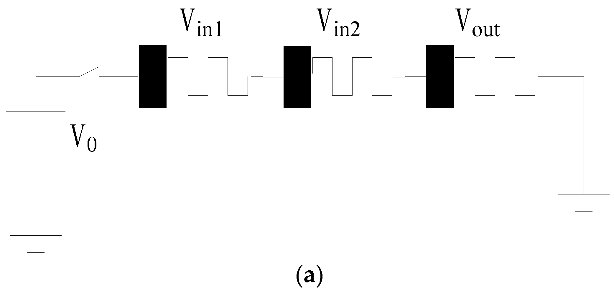
[13] proposed Memristor-Aided Logic (MAGIC), which uses the memristors with previous data as input and output. There is no need for a complicated structure to execute MAGIC, which needs only a voltage to perform various basic logic gates, as shown in
Figure 1. The logical state of a MAGIC gate can be represented by the value of memristive resistance, where high resistance represents logical “0” and low resistance represents logical “1”. The high resistance is named
“Roff”“Roff”, and the low resistance is named
”Ron””Ron”. The logical states of the memristor represent the input and output values of a MAGIC gate. Compared to an IMPLY logic gate, a MAGIC gate requires separate memristors for the input and output. The inputs depend on the initial logical states of input memristors, and the output is determined by the final logical state of the output memristor. The input and output states of MAGIC logic are stored in separate memristors, ensuring a stable and potentially repeatable operation process. MAGIC can accomplish NOT, AND, NAND, OR, and NOR operations, which form a complete set.
Figure 1 displays the various architectures of MAGIC-based NAND gates, NOR gates, and other gates, which vary in accordance with the amount of input data. Multi-bit input logic gates require a greater number of serial or parallel memristors. Therefore, current circuit designs and simulations based on MAGIC primarily concentrate on dual-input logic gates, which can be performed in a crossbar array
[14]. The application of MAGIC NOR gates in memristive crossbar arrays greatly improves circuit performance and reduces circuit power consumption. All basic operations based on MAGIC require more than one clock, so the operation speed of MAGIC is slightly slow. In addition, MAGIC gates suffer from state drift and lack signal restoration, which puts forward a higher demand to circuit design.
Figure 1. MAGIC gates
[13]. (
a) Schematic of a two-input AND gate. (
b) Schematic of a two-input OR gate. (
c) Schematic of a two-input NAND gate. (
d) Schematic of a two-input NOR gate.
4. Memristor Ratioed Logic (MRL)
It can be challenging to integrate standard CMOS logic and memristive logic in a crossbar array. However, in order to achieve compatibility between memristive devices and CMOS in logic circuits, there are a few requirements that must be met. Firstly, the process of memristors should be compatible with CMOS technology. Secondly, the input and output logical states must be represented by voltage instead of resistance. Thirdly, the additional circuitry required for connecting the memristive device layers to the CMOS layers should be minimized. To address these concerns, Kvatinsky et al.
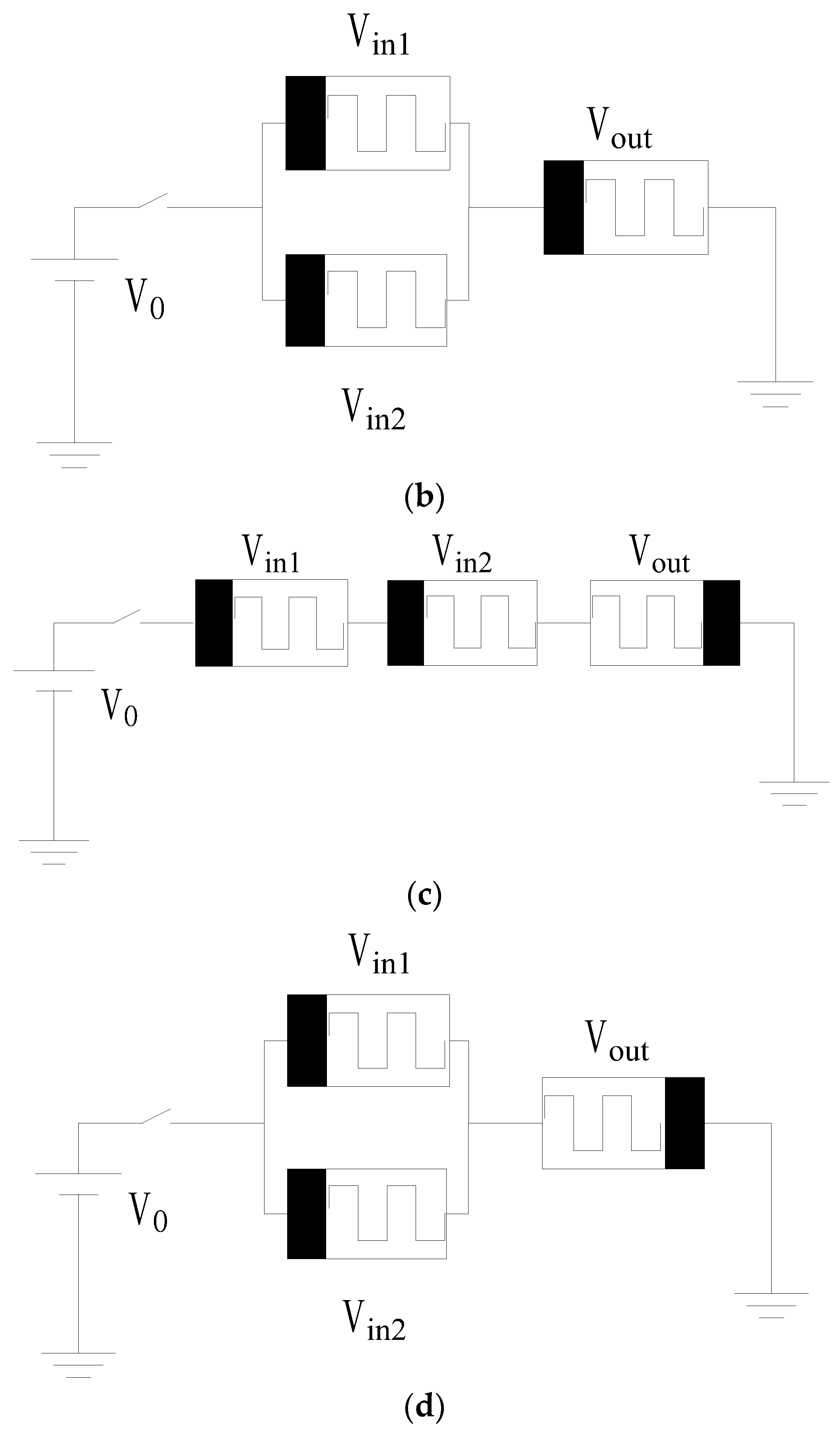
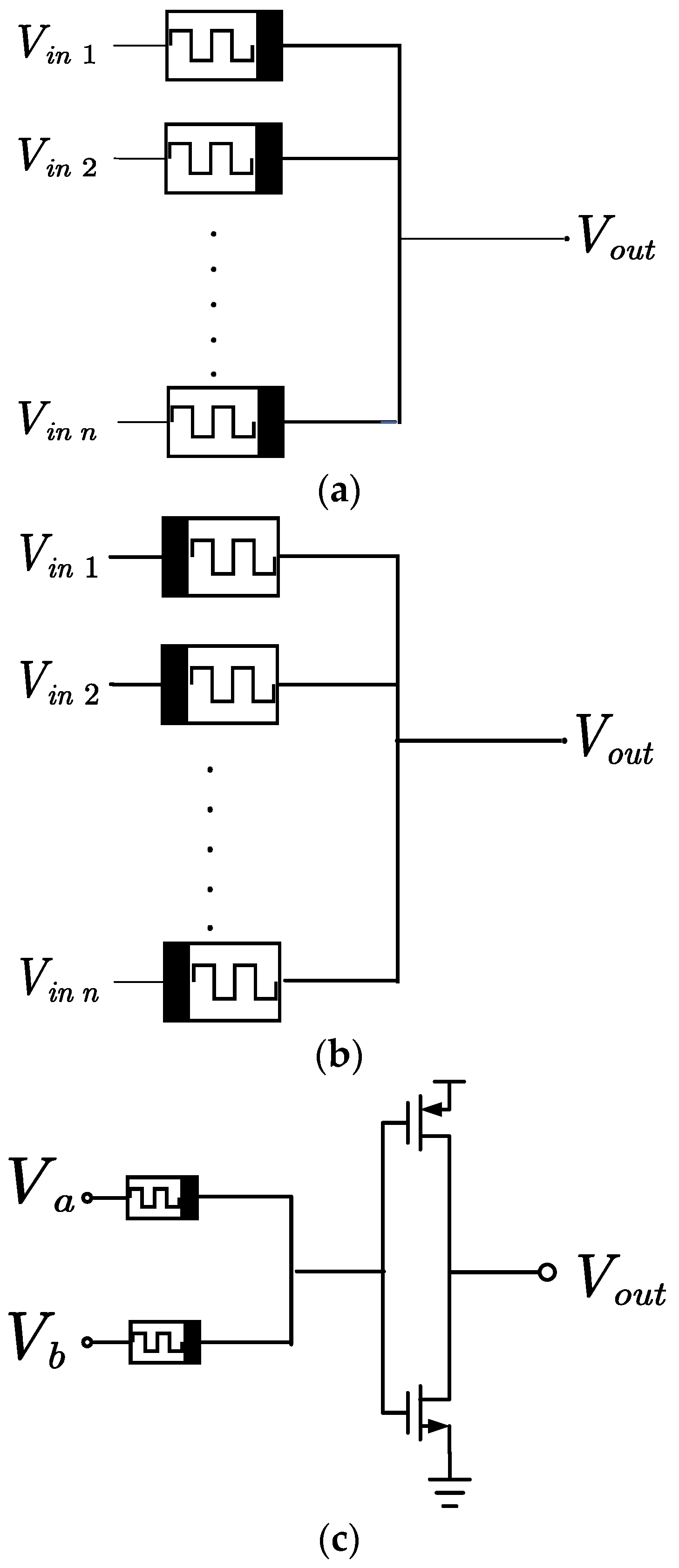
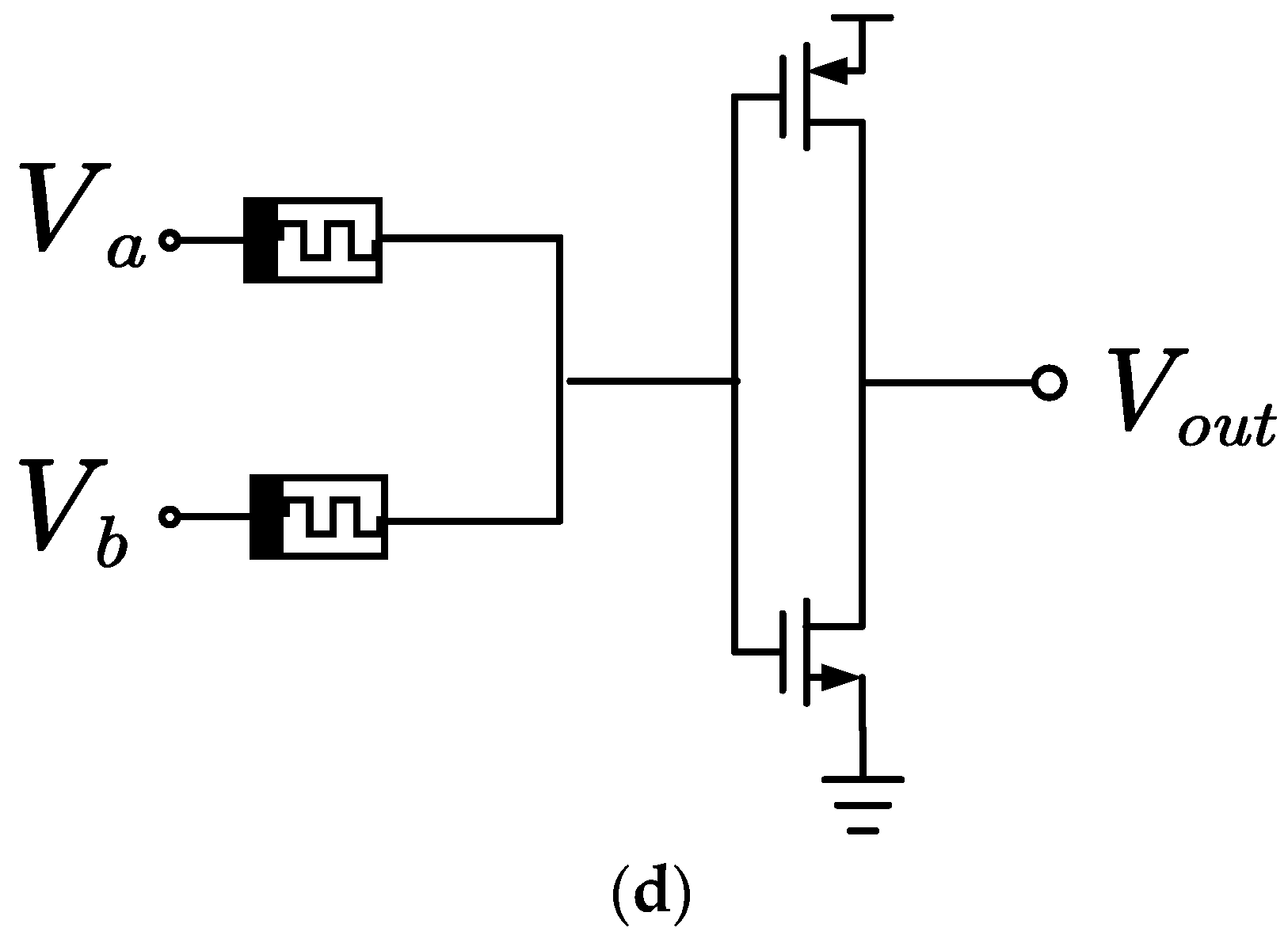
[15] proposed a memristor-based logic that is compatible with CMOS logic and is named Memristor Ratioed Logic (MRL). The schematic of MRL AND, OR, NAND and NOR logic gates is demonstrated in
Figure 2. Boolean AND/OR operations are accomplished by memristors with programmable resistance, while NOT operation is achieved by CMOS inverters, making it a complete logic family. In MRL, memristors serve as computing components instead of memory for saving logical states. The logical state in MRL is represented as a voltage, where logic “1” and logic “0” correspondto high and low voltages, respectively, similar to CMOS. The initial logical state of a memristive device does not affect the output logical state, but only the computing efficiency. Furthermore, MRL logic enables more convenient logic operations without the need for extra reading-writing circuits but cannot implement computation and memory simultaneously. Due to the segregation of computation and memory, MRL is not an effective solution to the Von Neumann bottleneck problem, but rather a method to achieve compatibility between memristors and CMOS circuits. MRL-based circuit designs have been extensively studied, with adders and comparators being accomplished through simulations. Vinukollu et al.
[16] proposed an MRL-based four-bit carry lookahead adder. Without changing any operations, this carry lookahead adder employs MRL gates to replace some other logic gates, which reduces the number of memristors, minimizes circuitry and power consumption, and decreases the delay time. Wang et al.
[17] proposed a D flip-flop and a JK flip-flop based on MRL. The D flip-flop consists of five memristors and an NMOS transistor, while the JK flip-flop is composed of seven memristors and two NMOS transistors. Compared to the traditional design method, the flip-flop based on MRL requires fewer MOSFETs. Additionally, due to the nanoscale size of memristors, MRL-based flip-flops have as impler circuit structure, lower power consumption, and smaller circuit area. Paramasivam et al.
[18] proposed a two-bit CMOS digital comparator utilizing MRL gates. MRL gates, consisting of memristive devices and CMOS inverters, decrease the number of memristors needed in the circuit, leading to reduced power consumption, a smaller area, and lower computing complexity for the comparator. Experimental results show an 18.74% reduction in circuit power consumption compared to traditional CMOS logic, and a 32.14% decrease in circuit area compared to resistance threshold logic.
Figure 2. MRL logic gates
[15]. (
a) Schematic of an N-input AND gate. (
b) Schematic of an N-input OR gate. (
c) Schematic of a two-input NAND gate. (
d) Schematic of a two-input NOR gate.
5. Memristive Threshold Logic (MTL)
Memristive threshold logic is a non-traditional form of logic that utilizes memristors to determine input weights and achieve threshold control. The output is generated if the comparison surpasses the threshold. Lageweg et al.
[19] introduced the Linear Threshold Gate (LTG), which uses tunnel junctions, capacitors, and voltage sources. It can perform any linear separable Boolean operations as
[20]:
Voting logic, which utilizes binary inputs and equal weights, is a subset of threshold logic. It is essential to note that the numerical expressions of threshold logic form the basis of neural computation. The simulation of threshold logic designs has verified the optimization in both area and power consumption. To accomplish threshold logic, the design that integrates programmable CMOS and memristors has been proposed, where CMOS logic is applied for signal amplification and inversion
[21]. Another design that adds current mirror at the input to perform threshold logic is introduced in
[22]. A PMOS current mirror is used as a current comparator for the purpose of comparing the sum of currents flowing through all the input memristors with a pre-specified threshold value. The input memristors determine the input weights of the threshold gate and convert the input voltages into currents, with the magnitude of the current generated by each memristor being defined by its respective weight. By comparing the input current with the reference current, namely the threshold value, the output of the threshold gate is determined as either logical “1” or logical “0”, depending on whether the sum of the input current exceeds the threshold value or not, respectively. However, as the application of a current mirror can lead to a reverse flow of current, a design has been proposed in
[23] whereby transfer transistors replace the current mirror after the input memristors. Moreover, the transistors are equipped with controllable switches that enable the reference current to be increased up to one to six times. In terms of current comparison, the Traff comparator
[24], which comes with positive feedback properties, has a faster process speed when compared to the design proposed in
[22]. Consequently, the threshold logic gates
[23] that come with programmable input weights and threshold values provide a higher degree of flexibility for the implementation of logical functions.
 +1 credit