Your browser does not fully support modern features. Please upgrade for a smoother experience.
Submitted Successfully!
 +1 credit
Thank you for your contribution! You can also upload a video entry or images related to this topic.
For video creation, please contact our Academic Video Service.
| Version | Summary | Created by | Modification | Content Size | Created at | Operation |
|---|---|---|---|---|---|---|
| 1 | Giovanni Pau | -- | 2503 | 2023-05-28 17:18:04 | | | |
| 2 | Sirius Huang | Meta information modification | 2503 | 2023-05-29 02:43:54 | | |
Video Upload Options
We provide professional Academic Video Service to translate complex research into visually appealing presentations. Would you like to try it?
Cite
If you have any further questions, please contact Encyclopedia Editorial Office.
Sathish, K.; Cv, R.; Ab Wahab, M.N.; Anbazhagan, R.; Pau, G.; Akbar, M.F. Underwater Communication Protocols. Encyclopedia. Available online: https://encyclopedia.pub/entry/44935 (accessed on 19 June 2026).
Sathish K, Cv R, Ab Wahab MN, Anbazhagan R, Pau G, Akbar MF. Underwater Communication Protocols. Encyclopedia. Available at: https://encyclopedia.pub/entry/44935. Accessed June 19, 2026.
Sathish, Kaveripakam, Ravikumar Cv, Mohd Nadhir Ab Wahab, Rajesh Anbazhagan, Giovanni Pau, Muhammad Firdaus Akbar. "Underwater Communication Protocols" Encyclopedia, https://encyclopedia.pub/entry/44935 (accessed June 19, 2026).
Sathish, K., Cv, R., Ab Wahab, M.N., Anbazhagan, R., Pau, G., & Akbar, M.F. (2023, May 28). Underwater Communication Protocols. In Encyclopedia. https://encyclopedia.pub/entry/44935
Sathish, Kaveripakam, et al. "Underwater Communication Protocols." Encyclopedia. Web. 28 May, 2023.
Copy Citation
Underwater Wireless Sensor Networks (UWSNs) have recently established themselves as an extremely interesting area of research thanks to the mysterious qualities of the ocean. The UWSN consists of sensor nodes and vehicles working to collect data and complete tasks. The battery capacity of sensor nodes is quite limited, which means that the UWSN network needs to be as efficient as it can possibly be. It is difficult to connect with or update a communication that is taking place underwater due to the high latency in propagation, the dynamic nature of the network, and the likelihood of introducing errors. This makes it difficult to communicate with or update a communication.
CB-UWSN
energy
telnet
routing protocols
UWSN
superframe
1. Introduction
The ocean significantly impacts human life because it covers a third of the earth’s surface. Because of the rough nature of the undersea environment, only a tiny portion of the sea’s influence on the environmental state has been studied. Because of the discovery of a chemical poison, an aquatic natural resource, and oil spillage in recent years, monitoring has become increasingly crucial [1]. Underwater sensor nodes construct a small-scale Cluster-Based Underwater Wireless Sensor Network (CB-UWSN) by gathering data via point-to-point communication. Sensor Nodes (SNs) are often attached to surveillance or Global Positioning System (GPS) systems, although they can also be permanently deployed on the water’s surface in UWSNs. These networks are inexpensive, have few limits on their functions, and are simple to deploy. Using a wireless sensor network, often known as a WSN, is a significant step toward unraveling the mystery of underwater settings [2].
The exploration of undiscovered oceans has inspired interest in the Internet of Underwater Things (IoUT), which intends to help solve problems in various industries, including the scientific community, security business, and others. The quantity of energy used and the quality of the networks used to transmit data are two significant issues in UWSN [3]. Because of the movement of the water, the function of SN is more complex and costly. Hop-to-hop communication consumes substantially less power than end-to-end transmission due to the periodic reorganization of the network’s structure [4][5]. When one node in the network wants to send data to another, the routing protocol establishes a path between the nodes in the proposed network. Between the source and the destination, routing table information is updated. Figure 1 depicts the general architectural diagram of CB-UWSN.
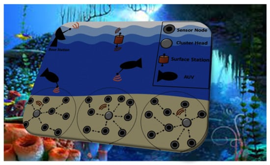
Figure 1. General architectural diagram of CB-UWSN.
The routing protocol is a collection of rules used to find the most efficient way to transport data from its point of origin to its final destination. Network specs, channel parameters, and performance metrics vary, making it challenging to determine the optimal route [6]. Underwater wireless sensor networks, also known as UWSNs, are responsible for collecting data from their sensor nodes and relaying them to a central hub, which then processes the data after sharing them with other networks, such as the Internet. Single-hop communication is possible in minimal sensor networks because the base station and motes (sensor nodes) are so close to each other that they can communicate directly; however, in most UWSN applications, the coverage area is so large that thousands of nodes must be placed. In this case, multi-hop communication is required because the majority of sensor nodes are so far from the sink node (gateway) that they cannot communicate directly [7]. Direct communication is referred to as “one hop”, while indirect communication is called “many hops”. In multi-hop communication, sensor nodes produce and distribute their own content and act as a conduit for other sensor nodes to connect with the base station. In addition to producing and distributing their content, they manufacture and distribute their advertisements. Routing is an essential network layer function. Routing is choosing the most efficient path between a source and a destination node [8].
2. Background on Communication Protocols
Underwater communication protocols are specialized sets of rules and procedures that are designed to facilitate the transmission and reception of data between underwater devices, such as sensors, vehicles, and buoys. These protocols are necessary because the underwater environment poses unique challenges that are not present in other communication scenarios. One major challenge of underwater communication is the high attenuation of electromagnetic waves in water, which limits the range and bandwidth of wireless communication protocols. As a result, most underwater communication protocols use acoustic signals to transmit data. Acoustic signals have a longer range in water than electromagnetic waves and can travel through the water with lower attenuation [9].
There are various types of underwater communication protocols, each with their own advantages and limitations. For example, some protocols, such as acoustic modems, are designed for high data rate applications and can transmit data at rates of several megabits per second over short distances. Other protocols, such as acoustic telemetry, are designed for long-range communication and can transmit data over distances of several kilometers, but at lower data rates. Underwater communication protocols also differ in terms of their operating frequency, modulation scheme, and error correction techniques. These parameters are important for optimizing the communication link and ensuring reliable data transfer between devices [10].
2.1. Ad Hoc On-Demand Distance Vector (AODV)
The only thing that needs to be altered to implement AODV while employing a reactive traffic routing protocol is the routing of existing paths. A node’s routing tables are where routing information is stored. Each mobile node’s “next-hop routing database” stores information about the mobile nodes to which that mobile node is capable of connecting in the next hop. If an entry in a routing table has not been used in a particular amount of time, it can be removed from the table. The destination sequence number is used on demand by both the AODV and the DSDV, but the AODV more frequently. If the transmitting node is unable to determine whether or not there is a path to the destination, AODV will begin looking for one [11].
2.2. Fisheye State Routing (FSR)
A multilayer and table-driven routing method for use in ad hoc networks, Fisheye State Routing is also known by its acronym FSR. This method utilizes the scope approach. The amount of overhead that is associated with routing in highly large networks that are prone to rapid change and dynamic behavior is something that needs to be reduced. In accordance with the methodology that underpins its scope, the connection state changes are periodically broadcast at a predetermined frequency. The entirety of the network is segmented into a variety of scopes, each of which is determined by the number of hops that are required to reach a particular node. These hops are counted from the root node backwards. Nodes that are considered to be within this distance of one another are referred to as inner nodes, while nodes that are further apart are referred to as outer nodes.
The transmissions of the most recent connection state updates are made available to neighbors across a wide range of frequencies. Information is delivered at a lower frequency, while simultaneously increasing its frequency while connecting with neighbors that are closer to the sender. The accuracy of the connection state updates that the nodes receive as a direct result of this is much improved. It improves the precision of the path that packets are sent across when they are transferred [12].
2.3. Location-Aided Routing 1 (LAR1)
In wireless ad hoc networks, the LAR protocol is deployed as a kind of location-based and reactive routing. It accomplishes this by utilizing three separate packets, namely, the route request, the route reply, and the route error, in order to send and receive information between nodes and maintain stable connections. The LAR on-demand routing protocol functions in a manner that is comparable to that of the DSR (dynamic source routing) protocol. The LAR protocol, as opposed to the DSR protocol, makes use of location data in order to establish the borders of the “request zone”, which is the area in which it is feasible to discover new routes. This zone is defined in contrast to the DSR protocol, which does not make use of location data. As a direct result of this, the route requests will not be broadcast to the full of the network, but rather will only be transmitted by the nodes that are a part of the request zone. The originator provides a forecast about a spherical region that is termed the predicted zone. This region is the location in which the target object is most likely to be discovered at this same current time. The prediction is made by using data from the past [13].
2.4. Optimized Link State Routing Protocol (OLSR)
OLSR (optimized link state routing) is a prominent type of dynamic routing technique. Frequent transmissions of routing information from each network node ensure that all network nodes have the same comprehensive perspective. The protocol incurs significant extra expense due to its periodic structure. The problem is resolved since OLSR limits the amount of traffic that can be transferred. To achieve this purpose, multi-point relays (MPRs) are used; these devices are in charge of relaying and routing messages. Each node selects MPRs from among its neighboring nodes. It is advised that for optimal performance, a node choose MPRs that allow it to connect with at least one neighbor that is reachable over a hop-and-a-half path. MPRs are in charge of relaying control traffic generated by other nodes [14].
2.5. Source Tree Adaptive Routing—Least Overhead Routing Approach (STAR-LORA)
The STAR protocol was created to be used by both mobile and stationary nodes in a network context, such as the Internet or ad hoc networks. As a result, the protocol can be employed in any situation. The surrounding routers of a STAR router will require access to the source routing tree’s settings while configuring it. The source routing tree stores every possible connection that the router needs to communicate with any host or combination of hosts anywhere on the Internet or in the ad hoc network. A router will only change the source routing tree it uses to direct traffic after learning about new destinations, the risk of loops, node failure, or network breakup. This reduces the router’s power consumption and increases its data transfer capability. The STAR routing protocol can be implemented in a variety of ways, including using an optimum routing algorithm (ORA) or a least-overhead routing strategy (LORA) [15].
Telnet (Telecommunication Network) is an abbreviation for a network protocol that can be utilized across both Internet and LAN connections. This network protocol enables bidirectional, interactive communication over wide-area networks, such as the Internet, as well as more intimate networks, such as local area networks (LANs), and interactive, two-way communications, such as instant messaging. In most cases, Telnet can be used to establish a virtual terminal connection to the command line interface of a remote computer. This link, which is a byte-oriented data connection with 8 bits, is supported by the transmission control protocol (TCP). In the same frequency channel, dispersed user data are provided with Telnet control information. Because the user’s PC initiates contact, it is referred to as the “local computer” [16].
The term “remote computer” refers to the machine at the other end of a connection. The remote computer could be in the next room, in another city, or even in another country. Telnet is a protocol that allows a user to log in from any computer on the network. A remote session can be started by simply selecting a host machine. Everything typed after that gets forwarded to the other computer and vice versa until the session terminates.
Telnet is an application that, when run, connects the user’s computer to a server located somewhere on the network. After that, we may use the Telnet application to input commands, which will be performed just as if they were entered on the server’s console. This allows one to control the server and connect with other network server operators. Before beginning a Telnet session, you must first log in to the server using a valid username and password. Remote control of Web servers via the Telnet protocol is typical practice [17].
Figure 2 Depicts a Superframe design based on IEEE 802.15.4. The PAN coordinator can purposely limit the amount of time that can be spent on a channel by using a Superframe structure, as shown in Figure 1. The structure of the Superframe is created by the coordinator’s beacon, and it is then divided into sixteen slots of the same size, as seen in Figure 1. The beacon interval can range from 15 milliseconds to 245 s, and the frame is broadcast in the very first slot of the Superframe.
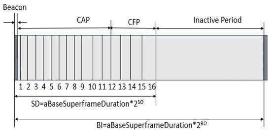
Figure 2. Superframe design based on IEEE 802.15.4.
Beacons are used to identify a PAN, synchronize the devices associated with the PAN, and explain the Superframe’s architecture. The time interval between beacon frames is divided into 16 equal parts, regardless of the time interval between Superframes. Any moment in time throughout the time slot may be used for data transmission; however, all data must be sent or received before the next Superframe period begins. The beacon frame contains, in addition to the Superframe specification and the current node notification, the pending node message and the current node notification.
There is a distinction to be made between the Superframe’s active period and its inactive phase. During moments of inactivity, the device will automatically transition to a lower-power mode. There are two unique time frames within the active period, known as the contention access period (CAP) and the contention-free period (CFP). Devices attempting to send data frames in the CAP use a procedure known as slotted CSMA/CA to acquire access to the wireless channel. The CFP, on the other hand, is used to transport data frames with assured quality of service since it is split into guaranteed time slots (GTSs). A coordinator, for example, might provide a GTS, particularly for applications that require real-time updates or a large amount of bandwidth.
Moore’s research on the emission of electric dipoles at the boundary surface dividing two media aroused interest in the use of electromagnetic waves to transport information between antennas immersed in a conducting medium. Moore and Blair investigated ELF transmissions between antennas submerged in a conducting half-space medium. The study was based on the assumption that a lateral wave with three components is the primary mode of communication between submerged antennas. These components are as follows: (1) a wave that travels along the sea surface; (2) a wave that travels directly from the transmitting dipole to the water’s surface; and (3) a wave that travels perpendicular to the water’s surface from the water’s surface to the receiving dipole.
With this notion, direct path attenuation was projected to be substantially greater than lateral wave attenuation. Waves reflected from the ocean floor were not taken into account because they would result in significantly more attenuation than the straight path. While very low frequency (ELF) transmission was considered, the displacement current commonly associated with a medium losing conductivity was disregarded. Figure 3 represents the communication model of the UWSN with various hardware and network assemblies.
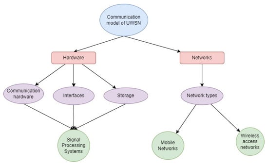
Figure 3. Communication model of UWSN.
References
- Srinivasulu, A.; Anand Kumar, G. Performance Analysis of Underwater Wireless Sensor Network by Deploying FTP, CBR, and VBR as Applications. J. Comput. Netw. Commun. 2022, 2022, 7143707.
- Luo, J.; Fan, L.; Wu, S.; Yan, X. Research on localization algorithms based on acoustic communication for underwater sensor networks. Sensors 2018, 18, 67.
- Heidemann, J.; Ye, W.; Wills, J.; Syed, A.; Li, Y. Research challenges and applications for underwater sensor networking. In Proceedings of the Wireless Communications and Networking Conference (WCNC 2006), Las Vegas, NV, USA, 3–6 April 2006; Volume 1, pp. 228–235.
- Yang, J.; Fei, Z.; Shen, J. Hole detection and shape-free representation and double landmarks based geographic routing in wireless sensor networks. Digit. Commun. Netw. 2015, 1, 75–83.
- Sathish, K.; Ravikumar, C.V.; Srinivasulu, A.; Rajesh, A.; Oyerinde, O.O. Performance and Improvement Analysis of the Underwater WSN Using a Diverse Routing Protocol Approach. J. Comput. Netw. Commun. 2022, 2022, 9418392.
- Anbazhagan, R.; Venkata, R.C.; Arena, F.; Pau, G. Investigation and Numerical Simulation of the Acoustic Target Strength of the Underwater Submarine Vehicle. Inventions 2022, 7, 111.
- Venkata, R.C.; Anbazhagan, R.; Pau, G. Review of Localization and Clustering in USV and AUV for Underwater Wireless Sensor Networks. Telecom 2023, 4, 43–64.
- Pughat, A.; Sharma, V. Performance analysis of an improved dynamic power management model in wireless sensor node. Digit. Commun. Netw. 2017, 3, 19–29.
- Zandi, R.; Kamarei, M.; Amiri, H. Underwater acoustic sensor network localization using four directional beams. In Proceedings of the 2013 21st Iranian Conference on Electrical Engineering (ICEE), Mashhad, Iran, 14–16 May 2013; pp. 1–6.
- Cui, J.H.; Kong, J.; Gerla, M.; Zhou, S. The challenges of building mobile underwater wireless networks for aquatic applications. IEEE Netw. 2006, 20, 12–18.
- Sathish, K.; Hamdi, M.; Chinthaginjala, R.; Pau, G.; Ksibi, A.; Anbazhagan, R.; Abbas, M.; Usman, M. Reliable Data Transmission in Underwater Wireless Sensor Networks Using a Cluster-Based Routing Protocol Endorsed by Member Nodes. Electronics 2023, 12, 1287.
- Li, J.; Gao, H.; Zhang, S.; Chang, S.; Chen, J.; Liu, Z. Self-localization of autonomous underwater vehicles with accurate sound travel time solution. Comput. Electr. Eng. 2016, 50, 26–38.
- Kalapraveen, B. Receiver design using artificial neural network for signal detection in MC-CDMA system. Int. J. Intell. Eng. Syst. 2017, 10, 66–74.
- Mridula, K.M.; Ameer, P.M. Localization under anchor node uncertainty for underwater acoustic sensor networks. Int. J. Commun. Syst. 2018, 31, e3445.
- Han, G.; Jiang, J.; Shu, L.; Xu, Y.; Wang, F. Localization algorithms of underwater wireless sensor networks: A survey. Sensors 2012, 12, 2026–2061.
- Moore, R.K. Effects of a Surrounding Conducting Medium on Antenna Analysis. IEEE Trans. Antennas Propag. 1963, 11, 216–225.
- Wait, J.R.; Collin, R.E.; Zucker, F.J. Electromagnetic Fields of Sources in Lossy Media. In Antenna Theory; McGraw Hill: New York, NY, USA, 1969; pp. 438–514.
More
Information
Contributors
MDPI registered users' name will be linked to their SciProfiles pages. To register with us, please refer to https://encyclopedia.pub/register
:
View Times:
2.0K
Revisions:
2 times
(View History)
Update Date:
29 May 2023
Table of Contents


Notice
You are not a member of the advisory board for this topic. If you want to update advisory board member profile, please contact office@encyclopedia.pub.
OK
Confirm
Only members of the Encyclopedia advisory board for this topic are allowed to note entries. Would you like to become an advisory board member of the Encyclopedia?
Yes
No
${ textCharacter }/${ maxCharacter }
Submit
Cancel
Back
Comments
${ item }
|
${ item.createdUser.fullName }
${ item.createdAt }
${ item.vote }
${ item.reply }
Delete
${ reply.createdUser.fullName }
${ reply.createdAt }
${ reply.vote }
Delete
There is no reply to this comment~
${ item.replyTextCharacter }/${ item.replyMaxCharacter }
Submit
Cancel
More
No more~
There is no comment~
${ textCharacter }/${ maxCharacter }
Submit
Cancel
${ selectedItem.replyTextCharacter }/${ selectedItem.replyMaxCharacter }
Submit
Cancel
Confirm
Are you sure to Delete?
Yes
No