 +1 credit
| Version | Summary | Created by | Modification | Content Size | Created at | Operation |
|---|---|---|---|---|---|---|
| 1 | Annunziata Nusca | -- | 6686 | 2023-05-19 10:48:24 | | | |
| 2 | Beatrix Zheng | + 2 word(s) | 6688 | 2023-05-22 02:58:58 | | |
Video Upload Options
Computed tomography (CT) scanning has recently assumed a first-pillar role in the preoperative planning of patients undergoing transcatheter structural heart procedures (e.g., transcatheter aortic valve implantation, TAVI; MitraClip; Triclip; left atrial appendage occlusion, LAAO). A careful preprocedural assessment is crucial for achieving the best possible result, and, currently, CT represents the paramount technique to obtain morphological data on cardiac and vessel structures, thus allowing to choose the most appropriate vascular approach, the type and size of devices, and all the required steps to meet procedural expectations. The image reconstruction accuracy also provides information to predict potential complications such as misplacements and leakages.
1. Introduction
2. Computed Tomography and Aortic Valve
CT Assessment of the Aortic Valve for Transcatheter Procedures
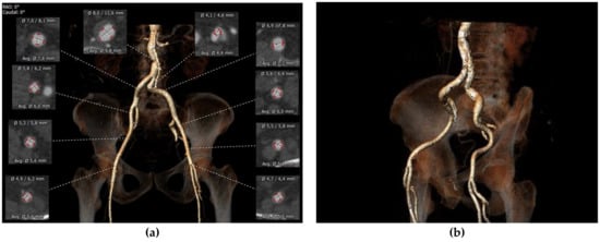
Peripheral Access
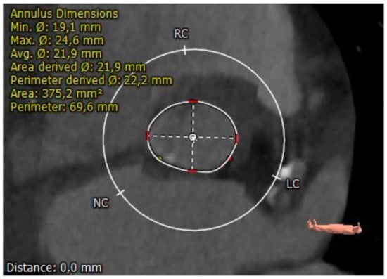
Aortic Annulus
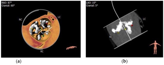
Aortic Leaflets
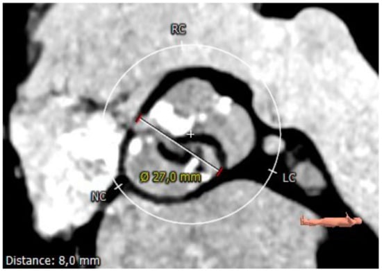
Coronary Ostia
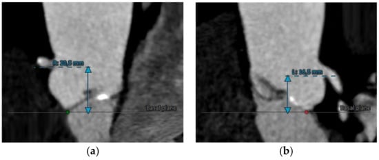
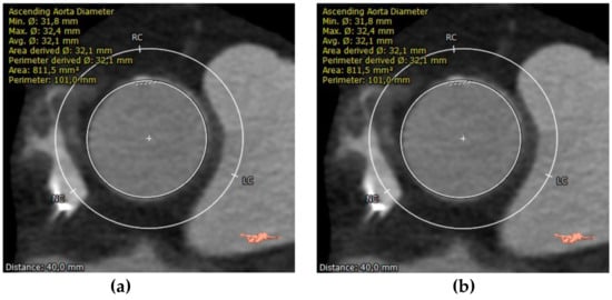
Sinotubular Junction (STJ) and Proximal Aorta
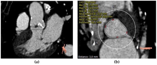
Left Ventricular Outflow Tract (LVOT) and Septum
3. Computed Tomography and Mitral Valve
CT Assessment of the Mitral Apparatus for Transcatheter Procedures
Annulus Sizing
Measurement of the mitral annulus is of primary importance since inaccurate sizing has devastating consequences. Moreover, given the complex mitral annulus 3D shape, collecting annular sizing could be challenging [60]. A direct calculation method involves tracing the edges of the annulus on conventional two-, three-, four-chamber, and short-axis views along the posterior mitral leaflet insertion and fibrous continuity. However, this method is time-consuming and can lead to an oversized device, increasing the risk of left ventricular outflow tract obstruction (LVOT). Blanke et al. developed a more straightforward method that assumes assimilating the mitral annulus to a planar D shape; given these premises, the two fibrous trigones are connected along a virtually straight line, effectively excluding the anterior horn [61]. Since the dimensions of the mitral annulus change during the cardiac cycle, the calculations are performed in the cardiac cycle phase in which the annulus is larger. Area and perimeter are the most used measures. However, other parameters are developed, such as the trigone–trigone distance; the intercommissural distance, which corresponds to the maximum diameter of the annulus parallel to the trigone–trigone distance; the septum-lateral distance, which corresponds to the maximum diameter of the annulus perpendicular to the IC. It must be emphasized that each device refers to different parameters for sizing [59].Predicting LVOT Obstruction
Landing Zone
Mitral Anulus Calcification
Vascular Structures
Other Potential Use of CT in Transcatheter Mitral Valve Interventions
Computed Tomography and Tricuspid Valve
CT Assessment of the Tricuspid Apparatus for Transcatheter Procedures
Computed Tomography and Left Atrial Appendage
CT Assessment in LAA Transcatheter Closure
6. Conclusions
References
- Schoenhagen, P.; Numburi, U.; Halliburton, S.S.; Aulbach, P.; Von Roden, M.; Desai, M.Y.; Rodriguez, L.L.; Kapadia, S.R.; Tuzcu, E.M.; Lytle, B.W. Three-dimensional imaging in the context of minimally invasive and transcatheter cardiovascular interventions using multi-detector computed tomography: From pre-operative planning to intra-operative guidance. Eur. Hear. J. 2010, 31, 2727–2740.
- Boxt, L.M.; Lipton, M.J.; Kwong, R.Y.; Rybicki, F.; E Clouse, M. Computed tomography for assessment of cardiac chambers, valves, myocardium and pericardium. Cardiol. Clin. 2003, 21, 561–585.
- Ecabert, O.; Peters, J.; Schramm, H.; Lorenz, C.; von Berg, J.; Walker, M.J.; Vembar, M.; Olszewski, M.E.; Subramanyan, K.; Lavi, G.; et al. Automatic Model-Based Segmentation of the Heart in CT Images. IEEE Trans. Med. Imaging 2008, 27, 1189–1201.
- Hu, S.; Hoffman, E.; Reinhardt, J. Automatic lung segmentation for accurate quantitation of volumetric X-ray CT images. IEEE Trans. Med. Imaging 2001, 20, 490–498.
- Bae, K.T.; Giger, M.L.; Chen, C.; Kahn, C.E. Automatic segmentation of liver structure in CT images. Med. Phys. 1993, 20, 71–78.
- Mir, A.; Hanmandlu, M.; Tandon, S. Texture analysis of CT images. IEEE Eng. Med. Biol. Mag. 1995, 14, 781–786.
- Yang, X.; He, X.; Zhao, J.; Zhang, Y.; Zhang, S.; Xie, P. COVID-CT-Dataset: A CT Scan Dataset about COVID-19. Mach. Learn. 2020.
- Sarma, A.; Heilbrun, M.E.; Conner, K.E.; Stevens, S.M.; Woller, S.C.; Elliott, C.G. Radiation and Chest CT Scan Examinations. Chest 2012, 142, 750–760.
- O’Connor, J.F.; Cohen, J.O. Computerized tomography (CAT scan, CT scan) in orthopaedic surgery. JBJS 1978, 60, 1096–1098.
- Patel, K.P.; Vandermolen, S.; Herrey, A.S.; Cheasty, E.; Menezes, L.; Moon, J.C.; Pugliese, F.; Treibel, T.A. Cardiac Computed Tomography: Application in Valvular Heart Disease. Front. Cardiovasc. Med. 2022, 9, 849540.
- Cammalleri, V.; Carpenito, M.; Bono, M.C.; Mega, S.; Ussia, G.P.; Grigioni, F. Transcatheter Tricuspid Valve Therapy: From Anatomy to Intervention. Front. Cardiovasc. Med. 2021, 8, 778445.
- Cammalleri, V.; Carpenito, M.; De Stefano, D.; Ussia, G.P.; Bono, M.C.; Mega, S.; Nusca, A.; Cocco, N.; Nobile, E.; De Filippis, A.; et al. Novel Computed Tomography Variables for Assessing Tricuspid Valve Morphology: Results from the TRIMA (Tricuspid Regurgitation IMAging) Study. J. Clin. Med. 2022, 11, 2825.
- Cammalleri, V.; Mega, S.; Ussia, G.P.; Grigioni, F. Mitral and Tricuspid Valves Percutaneous Repair in Patients with Advanced Heart Failure. Hear. Fail. Clin. 2021, 17, 607–618.
- Hell, M.M.; Achenbach, S. CT support of cardiac structural interventions. Br. J. Radiol. 2019, 92, 20180707.
- Holmes, D.R.; Mack, M.J.; Kaul, S.; Agnihotri, A.; Alexander, K.P.; Bailey, S.R.; Calhoon, J.H.; Carabello, B.A.; Desai, M.Y.; Edwards, F.H.; et al. 2012 ACCF/AATS/SCAI/STS Expert Consensus Document on Transcatheter Aortic Valve Replacement. J. Am. Coll. Cardiol. 2012, 59, 1200–1254.
- Blanke, P.; Weir-McCall, J.R.; Achenbach, S.; Delgado, V.; Hausleiter, J.; Jilaihawi, H.; Marwan, M.; Norgaard, B.L.; Piazza, N.; Schoenhagen, P.; et al. Computed tomography imaging in the context of transcatheter aortic valve implantation (TAVI) / transcatheter aortic valve replacement (TAVR): An expert consensus document of the Society of Cardiovascular Computed Tomography. J. Cardiovasc. Comput. Tomogr. 2019, 13, 1–20.
- Chiocchi, M.; Ricci, F.; Pasqualetto, M.; D’errico, F.; Benelli, L.; Pugliese, L.; Cavallo, A.U.; Forcina, M.; Presicce, M.; De Stasio, V.; et al. Role of computed tomography in transcatheter aortic valve implantation and valve-in-valve implantation: Complete review of preprocedural and postprocedural imaging. J. Cardiovasc. Med. 2020, 21, 182–191.
- Binder, R.K.; Webb, J.G.; Willson, A.B.; Urena, M.; Hansson, N.C.; Norgaard, B.L.; Pibarot, P.; Barbanti, M.; Larose, E.; Freeman, M.; et al. The Impact of Integration of a Multidetector Computed Tomography Annulus Area Sizing Algorithm on Outcomes of Transcatheter Aortic Valve Replacement. J. Am. Coll. Cardiol. 2013, 62, 431–438.
- Corcione, N.; Morello, A.; Ferraro, P.; Cimmino, M.; Albanese, M.; Pepe, M.; Nestola, P.L.; Giordano, S.; Bardi, L.; Biondi-Zoccai, G.; et al. TAVI-CT score to evaluate the anatomic risk in patients undergoing transcatheter aortic valve implantation. Sci. Rep. 2022, 12, 1–9.
- Spaziano, M.; Chieffo, A.; Watanabe, Y.; Chandrasekhar, J.; Sartori, S.; Lefèvre, T.; Petronio, A.S.; Presbitero, P.; Tchetche, D.; Iadanza, A.; et al. Computed tomography predictors of mortality, stroke and conduction disturbances in women undergoing TAVR: A sub-analysis of the WIN-TAVI registry. J. Cardiovasc. Comput. Tomogr. 2018, 12, 338–343.
- Gama, F.; Teles, R.; Oliveira, A.; Brizido, C.; Goncalves, P.; Brito, J.; Ferreira, A.; Abecasis, J.; Almeida, M.; Mendes, M. Predicting pacemaker implantation after TAVR with procedural CT. Eur. Hear. J. 2020, 41, ehaa946.0192.
- Gegenava, T.; van der Bijl, P.; Hirasawa, K.; Vollema, E.M.; van Rosendael, A.; van der Kley, F.; de Weger, A.; Hautemann, D.J.; Reiber, J.H.; Marsan, N.A.; et al. Feature tracking computed tomography-derived left ventricular global longitudinal strain in patients with aortic stenosis: A comparative analysis with echocardiographic measurements. J. Cardiovasc. Comput. Tomogr. 2019, 14, 240–245.
- Masson, J.-B.; Kovac, J.; Schuler, G.; Ye, J.; Cheung, A.; Kapadia, S.; Tuzcu, M.E.; Kodali, S.; Leon, M.B.; Webb, J.G. Transcatheter Aortic Valve Implantation: Review of the Nature, Management, and Avoidance of Procedural Complications. JACC: Cardiovasc. Interv. 2009, 2, 811–820.
- Hayashida, K.; Lefèvre, T.; Chevalier, B.; Hovasse, T.; Romano, M.; Garot, P.; Mylotte, D.; Uribe, J.; Farge, A.; Donzeau-Gouge, P.; et al. Transfemoral Aortic Valve Implantation: New Criteria to Predict Vascular Complications. JACC: Cardiovasc. Interv. 2011, 4, 851–858.
- Okuyama, K.; Jilaihawi, H.; Kashif, M.; Takahashi, N.; Chakravarty, T.; Pokhrel, H.; Patel, J.; Forrester, J.S.; Nakamura, M.; Cheng, W.; et al. Transfemoral Access Assessment for Transcatheter Aortic Valve Replacement: Evidence-based application of computed tomography over invasive angiography. Circ. Cardiovasc. Imaging 2015, 8, e001995.
- Reardon, M.J.; Van Mieghem, N.M.; Popma, J.J.; Kleiman, N.S.; Søndergaard, L.; Mumtaz, M.; Adams, D.H.; Deeb, G.M.; Maini, B.; Gada, H.; et al. Surgical or Transcatheter Aortic-Valve Replacement in Intermediate-Risk Patients. N. Engl. J. Med. 2017, 376, 1321–1331.
- Lehmkuhl, L.; Foldyna, B.; Haensig, M.; Von Aspern, K.; Lücke, C.; Andres, C.; Grothoff, M.; Riese, F.; Nitzsche, S.; Holzhey, D.; et al. Role of preprocedural computed tomography in transcatheter aortic valve implantation. Fortschr. Geb. Rontgenstr. Nuklearmed. 2013, 185, 941–949.
- Jurencak, T.; Turek, J.; Kietselaer, B.L.J.H.; Mihl, C.; Kok, M.; Van Ommen, V.G.V.A.; Van Garsse, L.A.F.M.; Nijssen, E.C.; Wildberger, J.E.; Das, M. MDCT evaluation of aortic root and aortic valve prior to TAVI. What is the optimal imaging time point in the cardiac cycle? Eur. Radiol. 2015, 25, 1975–1983.
- Adams, D.H.; Popma, J.J.; Reardon, M.J.; Yakubov, S.J.; Coselli, J.S.; Deeb, G.M.; Gleason, T.G.; Buchbinder, M.; Hermiller, J., Jr.; Kleiman, N.S.; et al. Transcatheter Aortic-Valve Replacement with a Self-Expanding Prosthesis. N. Engl. J. Med. 2014, 370, 1790–1798.
- Mack, M.J.; Leon, M.B.; Thourani, V.H.; Makkar, R.; Kodali, S.K.; Russo, M.; Kapadia, S.R.; Malaisrie, S.C.; Cohen, D.J.; Pibarot, P.; et al. Transcatheter Aortic-Valve Replacement with a Balloon-Expandable Valve in Low-Risk Patients. N. Engl. J. Med. 2019, 380, 1695–1705.
- Mylotte, D.; Dorfmeister, M.; Elhmidi, Y.; Mazzitelli, D.; Bleiziffer, S.; Wagner, A.; Noterdaeme, T.; Lange, R.; Piazza, N. Erroneous Measurement of the Aortic Annular Diameter Using 2-Dimensional Echocardiography Resulting in Inappropriate CoreValve Size Selection: A retrospective comparison with multislice computed tomography. JACC: Cardiovasc. Interv. 2014, 7, 652–661.
- Helmy, S.M.; Karim, S.A. Multimodality imaging in aortic stenosis. Hear. Views 2022, 23, 22.
- Vincent, F.; Ternacle, J.; Denimal, T.; Shen, M.; Redfors, B.; Delhaye, C.; Simonato, M.; Debry, N.; Verdier, B.; Shahim, B.; et al. Transcatheter Aortic Valve Replacement in Bicuspid Aortic Valve Stenosis. Circulation 2021, 143, 1043–1061.
- Tanaka, R.; Yoshioka, K.; Niinuma, H.; Ohsawa, S.; Okabayashi, H.; Ehara, S. Diagnostic Value of Cardiac CT in the Evaluation of Bicuspid Aortic Stenosis: Comparison With Echocardiography and Operative Findings. Am. J. Roentgenol. 2010, 195, 895–899.
- Popma, J.J.; Ramadan, R. CT Imaging of Bicuspid Aortic Valve Disease for TAVR ∗. JACC: Cardiovasc. Imaging 2016, 9, 1159–1163.
- Doris, M.K.; Jenkins, W.; Robson, P.; Pawade, T.; Andrews, J.P.; Bing, R.; Cartlidge, T.; Shah, A.; Pickering, A.; Williams, M.C.; et al. Computed tomography aortic valve calcium scoring for the assessment of aortic stenosis progression. Heart 2020, 106, 1906–1913.
- Feuchtner, G.M.; Müller, S.; Grander, W.; Alber, H.F.; Bartel, T.; Friedrich, G.J.; Reinthaler, M.; Pachinger, O.; Nedden, D.Z.; Dichtl, W. Aortic valve calcification as quantified with multislice computed tomography predicts short-term clinical outcome in patients with asymptomatic aortic stenosis. J. Hear. Valve Dis. 2006, 15, 494–498.
- Rosenhek, R.; Binder, T.; Porenta, G.; Lang, I.; Christ, G.; Schemper, M.; Maurer, G.; Baumgartner, H. Predictors of Outcome in Severe, Asymptomatic Aortic Stenosis. New Engl. J. Med. 2000, 343, 611–617.
- Leber, A.W.; Kasel, M.; Ischinger, T.; Ebersberger, U.H.; Antoni, D.; Schmidt, M.; Riess, G.; Renz, V.; Huber, A.; Helmberger, T.; et al. Aortic valve calcium score as a predictor for outcome after TAVI using the CoreValve revalving system. Int. J. Cardiol. 2011, 166, 652–657.
- Haensig, M.; Lehmkuhl, L.; Rastan, A.J.; Kempfert, J.; Mukherjee, C.; Gutberlet, M.; Holzhey, D.; Mohr, F.W. Aortic valve calcium scoring is a predictor of significant paravalvular aortic insufficiency in transapical-aortic valve implantation. Eur. J. Cardio-Thoracic Surg. 2012, 41, 1234–1241.
- Lee, J.A.; Singh, T.; Ben Dor, I.; Torguson, R.; Okubagzi, P.; Satler, L.; Goldstein, S.; Taylor, A.; Weigold, W.G.; Pichard, A.; et al. AAortic valve calcium score by computed tomography in predicting perivalvular aortic insufficiency post transcatheter aortic valve implantation (TAVI). J. Am. Coll. Cardiol. 2012, 59, E1962.
- Unbehaun, A.; Pasic, M.; Dreysse, S.; Drews, T.; Kukucka, M.; Mladenow, A.; Ivanitskaja-Kühn, E.; Hetzer, R.; Buz, S. Transapical Aortic Valve Implantation: Incidence and predictors of paravalvular leakage and transvalvular regurgitation in a series of 358 patients. J. Am. Coll. Cardiol. 2012, 59, 211–221.
- Feuchtner, G.; Plank, F.; Bartel, T.; Mueller, S.; Leipsic, J.; Schachner, T.; Müller, L.; Friedrich, G.; Klauser, A.; Grimm, M.; et al. Prediction of Paravalvular Regurgitation After Transcatheter Aortic Valve Implantation by Computed Tomography: Value of Aortic Valve and Annular Calcification. Ann. Thorac. Surg. 2013, 96, 1574–1580.
- Ribeiro, H.B.; Nombela-Franco, L.; Urena, M.; Mok, M.; Pasian, S.; Doyle, D.; DeLarochellière, R.; Côté, M.; Laflamme, L.; DeLarochellière, H.; et al. Coronary Obstruction Following Transcatheter Aortic Valve Implantation: A systematic review. JACC: Cardiovasc. Interv. 2013, 6, 452–461.
- Jilaihawi, H.; Chin, D.; Spyt, T.; Jeilan, M.; Vasa-Nicotera, M.; Bence, J.; Logtens, E.; Kovac, J. Prosthesis-patient mismatch after transcatheter aortic valve implantation with the Medtronic-Corevalve bioprosthesis. Eur. Heart J. 2009, 31, 857–864.
- Delgado, V.; Ng, A.C.T.; Shanks, M.; Van Der Kley, F.; Schuijf, J.D.; Van De Veire, N.R.L.; Kroft, L.; De Roos, A.; Schalij, M.J.; Bax, J.J. Transcatheter aortic valve implantation: Role of multimodality cardiac imaging. Expert Rev. Cardiovasc. Ther. 2010, 8, 113–123.
- Piazza, N.; Nuis, R.-J.; Tzikas, A.; Otten, A.; Onuma, Y.; García-García, H.; Schultz, C.; van Domburg, R.; van Es, G.-A.; van Geuns, R.; et al. Persistent conduction abnormalities and requirements for pacemaking six months after transcatheter aortic valve implantation. Eurointervention 2010, 6, 475–484.
- Jilaihawi, H.; Chin, D.; Vasa-Nicotera, M.; Jeilan, M.; Spyt, T.; Ng, G.A.; Bence, J.; Logtens, E.; Kovac, J. Predictors for permanent pacemaker requirement after transcatheter aortic valve implantation with the CoreValve bioprosthesis. Am. Hear. J. 2009, 157, 860–866.
- Moreno, R.; Calvo, L.; García, E.; Dobarro, D. Severe septal hypertrophy: Is it necessarily a contraindication for the transcatheter implantation of an Edwards-Sapien prosthesis? Rev. Esp. Cardiol. 2010, 63, 241–242.
- Stolzmann, P.; Scheffel, H.; Trindade, P.T.; Plass, A.R.; Husmann, L.; Leschka, S.; Genoni, M.; Marincek, B.; Kaufmann, P.A.; Alkadhi, H. Left Ventricular and Left Atrial Dimensions and Volumes: Comparison between dual-source CT and echo-cardiography. Investig. Radiol. 2008, 43, 284–289.
- Okuno, T.; Asami, M.; Heg, D.; Lanz, J.; Praz, F.; Hagemeyer, D.; Brugger, N.; Gräni, C.; Huber, A.; Spirito, A.; et al. Impact of Left Ventricular Outflow Tract Calcification on Procedural Outcomes After Transcatheter Aortic Valve Replacement. JACC: Cardiovasc. Interv. 2020, 13, 1789–1799.
- Faggioni, L.; Gabelloni, M.; Accogli, S.; Angelillis, M.; Costa, G.; Spontoni, P.; Petronio, A.S.; Caramella, D. Preprocedural planning of transcatheter mitral valve interventions by multidetector CT: What the radiologist needs to know. Eur. J. Radiol. Open 2018, 5, 131–140.
- Feuchtner, G.M.; Alkadhi, H.; Karlo, C.; Sarwar, A.; Meier, A.; Dichtl, W.; Leschka, S.; Blankstein, R.; Gruenenfelder, J.; Stolzmann, P.; et al. Cardiac CT Angiography for the Diagnosis of Mitral Valve Prolapse: Comparison with Echocardiography. Radiology 2010, 254, 374–383.
- Lee, A.P.-W.; Jin, C.-N.; Fan, Y.; Wong, R.H.; Underwood, M.J.; Wan, S. Functional Implication of Mitral Annular Disjunction in Mitral Valve Prolapse. JACC: Cardiovasc. Imaging 2017, 10, 1424–1433.
- Ewe, S.H.; Klautz, R.J.; Schalij, M.J.; Delgado, V. Role of computed tomography imaging for transcatheter valvular repair/insertion. Int. J. Cardiovasc. Imaging 2011, 27, 1179–1193.
- Naoum, C.; Leipsic, J.; Cheung, A.; Ye, J.; Bilbey, N.; Mak, G.; Berger, A.; Dvir, D.; Arepalli, C.; Grewal, J.; et al. Mitral Annular Dimensions and Geometry in Patients With Functional Mitral Regurgitation and Mitral Valve Prolapse. JACC: Cardiovasc. Imaging 2016, 9, 269–280.
- Nishimura, R.A.; Bonow, R.O. Percutaneous Repair of Secondary Mitral Regurgitation—A Tale of Two Trials. New Engl. J. Med. 2018, 379, 2374–2376.
- E van Wijngaarden, S.; Kamperidis, V.; Regeer, M.V.; Palmen, M.; Schalij, M.J.; Klautz, R.J.; Bax, J.J.; Marsan, N.A.; Delgado, V. Three-dimensional assessment of mitral valve annulus dynamics and impact on quantification of mitral regurgitation. Eur. Hear. J. Cardiovasc. Imaging 2017, 19, 176–184.
- Palmisano, A.; Nicoletti, V.; Colantoni, C.; Monti, C.B.; Pannone, L.; Vignale, D.; Darvizeh, F.; Agricola, E.; Schaffino, S.; De Cobelli, F.; et al. Dynamic changes of mitral valve annulus geometry at preprocedural CT: Relationship with functional classes of regurgitation. Eur. Radiol. Exp. 2021, 5, 1–12.
- Ranganath, P.; Moore, A.; Guerrero, M.; Collins, J.; Foley, T.; Williamson, E.; Rajiah, P. CT for Pre- and Postprocedural Evaluation of Transcatheter Mitral Valve Replacement. Radiographics 2020, 40, 1528–1553.
- Blanke, P.; Dvir, D.; Cheung, A.; Ye, J.; Levine, R.A.; Precious, B.; Berger, A.; Stub, D.; Hague, C.; Murphy, D.; et al. A simplified D-shaped model of the mitral annulus to facilitate CT-based sizing before transcatheter mitral valve implantation. J. Cardiovasc. Comput. Tomogr. 2014, 8, 459–467.
- Blanke, P.; Naoum, C.; Webb, J.; Dvir, D.; Hahn, R.T.; Grayburn, P.; Moss, R.R.; Reisman, M.; Piazza, N.; Leipsic, J. Multimodality Imaging in the Context of Transcatheter Mitral Valve Replacement. JACC: Cardiovasc. Imaging 2015, 8, 1191–1208.
- Wang, D.D.; Eng, M.H.; Greenbaum, A.; Myers, E.; Forbes, M.; Karabon, P.; Pantelic, M.; Song, T.; Nadig, J.; Guerrero, M.; et al. Validating a prediction modeling tool for left ventricular outflow tract (LVOT) obstruction after transcatheter mitral valve replacement (TMVR). Catheter. Cardiovasc. Interv. 2017, 92, 379–387.
- Yoon, S.-H.; Bleiziffer, S.; Latib, A.; Eschenbach, L.; Ancona, M.; Vincent, F.; Kim, W.-K.; Unbehaum, A.; Asami, M.; Dhoble, A.; et al. Predictors of Left Ventricular Outflow Tract Obstruction After Transcatheter Mitral Valve Replacement. JACC: Cardiovasc. Interv. 2019, 12, 182–193.
- Guerrero, M.; Salinger, M.; Pursnani, A.; Pearson, P.; Lampert, M.; Levisay, J.; Russell, H.; Feldman, T. Transseptal transcatheter mitral valve-in-valve: A step by step guide from preprocedural planning to postprocedural care. Catheter. Cardiovasc. Interv. 2017, 92, E185–E196.
- Gersh, B.J.; Maron, B.J.; Bonow, R.O.; Dearani, J.A.; Fifer, M.A.; Link, M.S.; Naidu, S.S.; Nishimura, R.A.; Ommen, S.R.; Rakowski, H.; et al. 2011 ACCF/AHA Guideline for the Diagnosis and Treatment of Hypertrophic Cardiomyopathy. Circulation 2011, 124, e783–e831.
- Babaliaros, V.C.; Greenbaum, A.B.; Khan, J.M.; Rogers, T.; Wang, D.D.; Eng, M.H.; O’Neill, W.W.; Paone, G.; Thourani, V.H.; Lerakis, S.; et al. Intentional Percutaneous Laceration of the Anterior Mitral Leaflet to Prevent Outflow Obstruction During Transcatheter Mitral Valve Replacement. JACC: Cardiovasc. Interv. 2017, 10, 798–809.
- Faletra, F.F.; Leo, L.A.; Paiocchi, V.L.; Caretta, A.; Viani, G.M.; Schlossbauer, S.A.; Demertzis, S.; Ho, S.Y. Anatomy of mitral annulus insights from non-invasive imaging techniques. Eur. Hear. J. Cardiovasc. Imaging 2019, 20, 843–857.
- Thaden, J.J.; Malouf, J.F.; Nkomo, V.T.; Pislaru, S.V.; Holmes, D.R.; Reeder, G.S.; Rihal, C.S.; Eleid, M.F. Mitral Valve Anatomic Predictors of Hemodynamic Success With Transcatheter Mitral Valve Repair. J. Am. Hear. Assoc. 2018, 7, e007315.
- Grover, R.; Ohana, M.; Arepalli, C.D.; Sellers, S.L.; Mooney, J.; Kueh, S.-H.; Kim, U.; Blanke, P.; Leipsic, J.A. Role of MDCT Imaging in Planning Mitral Valve Intervention. Curr. Cardiol. Rep. 2018, 20, 16.
- Natarajan, N.; Patel, P.; Bartel, T.; Kapadia, S.; Navia, J.; Stewart, W.; Tuzcu, E.M.; Schoenhagen, P. Peri-procedural imaging for transcatheter mitral valve replacement. Cardiovasc. Diagn. Ther. 2016, 6, 144–159.
- Storz, C.; Mangold, S.; Mueller, K.A.; Lausberg, H.; Gatidis, S.; Heber, S.D.; Schlett, C.L.; Nikolaou, K.; Bamberg, F. Cardiac CT for Guiding Mitral Valve Interventions. Curr. Cardiovasc. Imaging Rep. 2017, 10, 1–10.
- Rottländer, D.; Ballof, J.; Gödde, M.; Degen, H.; Ögütcü, A.; Alektorov, K.; Chatrou, M.; Heintzen, M.P.; Haude, M. CT-Angiography to predict outcome after indirect mitral annuloplasty in patients with functional mitral regurgitation. Catheter. Cardiovasc. Interv. 2020, 97, 495–502.
- Rottländer, D.; Gödde, M.; Degen, H.; Ögütcü, A.; Saal, M.; Haude, M. Procedural planning of CS -based indirect mitral annuloplasty using CT-angiography. Catheter. Cardiovasc. Interv. 2021, 98, 1393–1401.
- Urena, M.; Himbert, D.; Brochet, E.; Carrasco, J.L.; Iung, B.; Nataf, P.; Vahanian, A. Transseptal Transcatheter Mitral Valve Replacement Using Balloon-Expandable Transcatheter Heart Valves. JACC: Cardiovasc. Interv. 2017, 10, 1905–1919.
- Hosoba, S.; Mori, M.; Goto, Y.; Fukumoto, Y.; Shimura, T.; Yamamoto, M. Hypo-attenuated leaflet thickening in surgically-implanted mitral bioprosthesis. J. Cardiothorac. Surg. 2020, 15, 74–77.
- Kaewkes, D.; Patel, V.; Ochiai, T.; Flint, N.; Ahmad, Y.; Kim, I.; Koseki, K.; Sharma, R.; Joseph, J.; Yoon, S.-H.; et al. Usefulness of Computed Tomography to Predict Mitral Stenosis After Transcatheter Mitral Valve Edge-to-Edge Repair. Am. J. Cardiol. 2021, 153, 109–118.
- Hashimoto, G.; Fukui, M.; Sorajja, P.; Cavalcante, J.L. Essential roles for CT and MRI in timing of therapy in tricuspid regurgitation. Prog. Cardiovasc. Dis. 2019, 62, 459–462.
- Lewis, M.A.; Pascoal, A.; Keevil, S.F.; Lewis, C.A. Selecting a CT scanner for cardiac imaging: The heart of the matter. Br. J. Radiol. 2016, 89, 20160376.
- Pulerwitz, T.C.; Khalique, O.K.; Leb, J.; Hahn, R.T.; Nazif, T.; Leon, M.B.; George, I.; Vahl, T.P.; D’Souza, B.; Bapat, V.N.; et al. Optimizing Cardiac CT Protocols for Comprehensive Acquisition Prior to Percutaneous MV and TV Repair/Replacement. JACC: Cardiovasc. Imaging 2020, 13, 836–850.
- Lopes, B.B.; Sorajja, P.; Hashimoto, G.; Fukui, M.; Bapat, V.N.; Du, Y.; Bae, R.; Schwartz, R.S.; Stanberry, L.I.; Enriquez-Sarano, M.; et al. Tricuspid Anatomic Regurgitant Orifice Area by Functional DSCT. JACC: Cardiovasc. Imaging 2021, 14, 1669–1672.
- Praz, F.; Khalique, O.K.; Macedo, L.G.D.R.; Pulerwitz, T.C.; Jantz, J.; Wu, I.Y.; Kantor, A.; Patel, A.; Vahl, T.; Bapat, V.; et al. Comparison between Three-Dimensional Echocardiography and Computed Tomography for Comprehensive Tricuspid Annulus and Valve Assessment in Severe Tricuspid Regurgitation: Implications for Tricuspid Regurgitation Grading and Transcatheter Therapies. J. Am. Soc. Echocardiogr. 2018, 31, 1190–1202.e3.
- van Rosendael, P.J.; Joyce, E.; Katsanos, S.; Debonnaire, P.; Kamperidis, V.; van der Kley, F.; Schalij, M.J.; Bax, J.J.; Marsan, N.A.; Delgado, V. Tricuspid valve remodelling in functional tricuspid regurgitation: Multidetector row computed tomography insights. Eur. Hear. J. Cardiovasc. Imaging 2015, 17, 96–105.
- Hell, M.M.; Emrich, T.; Kreidel, F.; Kreitner, K.-F.; Schoepf, U.J.; Münzel, T.; von Bardeleben, R.S. Computed tomography imaging needs for novel transcatheter tricuspid valve repair and replacement therapies. Eur. Hear. J. Cardiovasc. Imaging 2020, 22, 601–610.
- Hahn, R.T.; Thomas, J.D.; Khalique, O.K.; Cavalcante, J.L.; Praz, F.; Zoghbi, W.A. Imaging Assessment of Tricuspid Regurgitation Severity. JACC: Cardiovasc. Imaging 2019, 12, 469–490.
- Fukuda, S.; Saracino, G.; Matsumura, Y.; Daimon, M.; Tran, H.; Greenberg, N.L.; Hozumi, T.; Yoshikawa, J.; Thomas, J.D.; Shiota, T. Three-Dimensional Geometry of the Tricuspid Annulus in Healthy Subjects and in Patients With Functional Tricuspid Regurgitation. Circulation 2006, 114, I492–I498.
- McElhinney, D.B.; Cabalka, A.K.; Aboulhosn, J.A.; Eicken, A.; Boudjemline, Y.; Schubert, S.; Himbert, D.; Asnes, J.D.; Salizzoni, S.; Bocks, M.L.; et al. Transcatheter Tricuspid Valve-in-Valve Implantation for the Treatment of Dysfunctional Surgical Bioprosthetic Valves: An International, Multicenter Registry Study. Circulation 2016, 133, 1582–1593.
- van Rosendael, P.J.; Kamperidis, V.; Kong, W.K.; van Rosendael, A.R.; van der Kley, F.; Marsan, N.A.; Delgado, V.; Bax, J.J. Computed tomography for planning transcatheter tricuspid valve therapy. Eur. Hear. J. 2016, 38, 665–674.
- Prakash, R.; Saw, J. Imaging for percutaneous left atrial appendage closure. Catheter. Cardiovasc. Interv. 2016, 92, 437–450.
- Oda, S.; Honda, K.; Yoshimura, A.; Katahira, K.; Noda, K.; Oshima, S.; Yuki, H.; Kidoh, M.; Utsunomiya, D.; Nakaura, T.; et al. 256-Slice coronary computed tomographic angiography in patients with atrial fibrillation: Optimal reconstruction phase and image quality. Eur. Radiol. 2015, 26, 55–63.
- Martinez, M.W.; Kirsch, J.; Williamson, E.E.; Syed, I.S.; Feng, D.; Ommen, S.; Packer, D.L.; Brady, P.A. Utility of Nongated Multidetector Computed Tomography for Detection of Left Atrial Thrombus in Patients Undergoing Catheter Ablation of Atrial Fibrillation. JACC: Cardiovasc. Imaging 2009, 2, 69–76.
- Hur, J.; Kim, Y.J.; Lee, H.-J.; Nam, J.E.; Hong, Y.; Kim, H.Y.; Lee, J.W.; Choi, B.W. Cardioembolic Stroke: Dual-Energy Cardiac CT for Differentiation of Left Atrial Appendage Thrombus and Circulatory Stasis. Radiology 2012, 263, 688–695.
- Rajwani, A.; Nelson, A.J.; Shirazi, M.G.; Disney, P.J.S.; Teo, K.S.L.; Wong, D.T.L.; Young, G.D.; Worthley, S.G. CT sizing for left atrial appendage closure is associated with favourable outcomes for procedural safety. Eur. Hear. J. Cardiovasc. Imaging 2016, 18, 1361–1368.
- Wang, Y.; Di Biase, L.; Horton, R.P.; Nguyen, T.; Morhanty, P.; Natale, A. Left Atrial Appendage Studied by Computed Tomography to Help Planning for Appendage Closure Device Placement. J. Cardiovasc. Electrophysiol. 2010, 21, 973–982.
- Jaguszewski, M.; Manes, C.; Puippe, G.; Salzberg, S.; Müller, M.; Falk, V.; Lüscher, T.; Luft, A.; Alkadhi, H.; Landmesser, U. Cardiac CT and echocardiographic evaluation of peri-device flow after percutaneous left atrial appendage closure using the AMPLATZER cardiac plug device. Catheter. Cardiovasc. Interv. 2014, 85, 306–312.
- Clemente, A.; Avogliero, F.; Berti, S.; Paradossi, U.; Jamagidze, G.; Rezzaghi, M.; Della Latta, D.; Chiappino, D. Multimodality imaging in preoperative assessment of left atrial appendage transcatheter occlusion with the Amplatzer Cardiac Plug. Eur. Hear. J. Cardiovasc. Imaging 2015, 16, 1276–1287.
- Diwakar, M.; Tripathi, A.; Joshi, K.; Sharma, A.; Singh, P.; Memoria, M.; Kumar, N. A comparative review: Medical image fusion using SWT and DWT. Mater. Today: Proc. 2020, 37, 3411–3416.
- Diwakar, M.; Tripathi, A.; Joshi, K.; Memoria, M.; Singh, P.; Kumar, N. Latest trends on heart disease prediction using machine learning and image fusion. Mater. Today: Proc. 2020, 37, 3213–3218.
- Joshi, K.; Kumar, M.; Tripathi, A.; Kumar, A.; Sehgal, J.; Barthwal, A. Latest Trends in Multi-Modality Medical Image Fusion: A Generic Review; Springer: Singapore, 2022; Volume 434, pp. 663–671.

