Your browser does not fully support modern features. Please upgrade for a smoother experience.
Submitted Successfully!
 +1 credit
Thank you for your contribution! You can also upload a video entry or images related to this topic.
For video creation, please contact our Academic Video Service.
| Version | Summary | Created by | Modification | Content Size | Created at | Operation |
|---|---|---|---|---|---|---|
| 1 | Yimin Feng | -- | 3330 | 2023-05-17 14:53:01 | | | |
| 2 | Camila Xu | Meta information modification | 3330 | 2023-05-18 03:30:08 | | | | |
| 3 | Camila Xu | + 3 word(s) | 3333 | 2023-05-19 08:45:43 | | |
Video Upload Options
We provide professional Academic Video Service to translate complex research into visually appealing presentations. Would you like to try it?
Cite
If you have any further questions, please contact Encyclopedia Editorial Office.
Feng, Y.; Zou, Q.; Zhou, C.; Liu, Y.; Peng, Q. Ontology-Based Architecture Process of System-of-Systems. Encyclopedia. Available online: https://encyclopedia.pub/entry/44442 (accessed on 25 June 2026).
Feng Y, Zou Q, Zhou C, Liu Y, Peng Q. Ontology-Based Architecture Process of System-of-Systems. Encyclopedia. Available at: https://encyclopedia.pub/entry/44442. Accessed June 25, 2026.
Feng, Yimin, Qiang Zou, Chenchu Zhou, Yusheng Liu, Qibo Peng. "Ontology-Based Architecture Process of System-of-Systems" Encyclopedia, https://encyclopedia.pub/entry/44442 (accessed June 25, 2026).
Feng, Y., Zou, Q., Zhou, C., Liu, Y., & Peng, Q. (2023, May 17). Ontology-Based Architecture Process of System-of-Systems. In Encyclopedia. https://encyclopedia.pub/entry/44442
Feng, Yimin, et al. "Ontology-Based Architecture Process of System-of-Systems." Encyclopedia. Web. 17 May, 2023.
Copy Citation
System-of-systems (SoS) architecture is crucial in managing complex and interconnected systems. An SoS architecture encompasses not solely its constituent systems (CSs) but also the interconnections and communication processes among them via their interfaces.
system of systems engineering
ontologies
model-based system engineering
1. Introduction
The advancement of high technology, particularly in information technology, has led to a significant increase in the frequency and closeness of connections and interactions between systems. As a result, system of systems (SoS) [1][2] and SoS engineering (SoSE) [1][2] have emerged as new areas of research in various fields such as military [3], aerospace [4], and health care [5], among others. The concept of architectural design in civil engineering has inspired the integration of architecture into SoSE to manage complexity and aid in system development and integration [6]. Architecture is the conceptual model that describes the fundamental properties of a system in its environment, including its components, relationships, and principles for design and evolution [7][8]. More particularly, an SoS architecture encompasses not solely its constituent systems (CSs) but also the interconnections and communication processes among them via their interfaces [9]. An Architecture Framework (AF) is a set of conventions and common practices established to guide the description of architecture within a specific domain [7]. In essence, the AF comprises many viewpoints (metamodel) covering various stages of the system life cycle and generating architecture views (models) to address the concerns of stakeholders [10].
AFs have been developed to model the complex relationships in SoSs and describe their architecture [11]. However, AFs are complex and time-consuming to create and implement, requiring significant resources such as time, money, and expertise [12]. The values of architecture descriptions are still under debate due to the construction of architecture views (or simply, views) and the development process of architecture viewpoints (or simply, viewpoints). The construction of views is often based on predefined scenarios and lacks analytical support, with vague or incomplete elements such as capability taxonomy, capability dependency, operational performer taxonomy, and operational activity flow present in early design stages [13]. The “Fit-for-Purpose” principle, introduced by the Department of Defense Architecture Framework (DoDAF) [8], simplifies architecture design and reduces development costs. However, successfully implementing this principle depends on clarifying relationships among views. While experienced experts may have more flexibility in applying this principle, less experienced engineers may encounter difficulties due to the lack of straightforward architectural processes.
Proposing an architecture development process for SoSs is challenging due to significant gaps in current modeling practices. Firstly, modeling languages lack well-defined semantics for SoS metamodels, such as Systems Modeling Language (SysML) [14], which limits their rigor [15]. Secondly, the complexity of SoSs requires representing architecture through multiple perspectives from different domains [16] (e.g., strategic, operational, and resource), posing the risks of misunderstandings and difficulties in bridging these domains. Finally, even within a single domain, selecting the appropriate views and determining their order is challenging due to the variation in model kinds (e.g., taxonomy, structure, connectivity, and process) [16].
Although SysML has limitations in describing SoS architecture, it can be enhanced by incorporating ontologies and reasoning as a complement [17][18]. Ontology is a formal and rigorous approach to knowledge representation, which can provide precise and unambiguous semantics for terms [19]. Several scholars and institutions have developed ontologies to depict different domains and applications by integrating the elements of a system’s architecture [20][21]. Building ontologies is a promising way to create a knowledge repository for SoS architectures. At the same time, a metamodel provides the foundation for defining basic concepts and relationships necessary for ontology creation and reasoning [22]. Despite differences in architectural elements across domains, they can be correlated with the formal semantics of ontologies. Views developed using different model kinds can be represented through various flows and relationships, including generalization, composition, dependency, connector, message, and transition. Accordingly, the selection and the sequence of views can be specified based on the organization of these relationships and flows.
Motivated by the observation above, SoS metamodels and ontologies are proposed to provide semantics for a shared understanding.
2. Ontology-Based Architecture Process of System-of-Systems
2.1. Architecture Framework
AFs serve different purposes and are defined using metamodels. Widely used AFs include Zachman [23], the Open Group Architecture Framework (TOGAF) [24], and the Department of Defense Architecture Framework (DoDAF) [8]. Although the Zachman framework does not explicitly propose the concept of “enterprise architecture”, it is a pioneering multi-perspective framework emphasizing the hierarchical and multi-perspective nature of complex systems’ cognition. TOGAF defines an enterprise as “a collection of organizations with a common goal”. Therefore, an SoS can also be considered a type of enterprise, and AFs are an efficient way to handle SoSs. While the Zachman framework and TOGAF define concepts with ambiguity, DoDAF takes data as the core and defines DoDAF Metamodel (DM2) for different situations. However, DoDAF is tailored by the Department of Defense to its military doctrine and may not apply directly to other countries or civilian domains. Governments and organizations such as the UK and NATO have proposed architecture frameworks, including the Ministry of Defense Architecture Framework (MODAF) [25] and NATO Architecture Framework (NAF) [26], respectively, for their military domains. Matching metamodels and defining concepts that effectively communicate between AFs is challenging due to their differing contents [27]. The Unified Architecture Framework (UAF) inherits and develops DM2, is compatible with existing AFs, and provides a more standardized approach to architecture description. UAF extends the application from the military domain to the general enterprise domain [28]. However, the UAF’s metamodel comprises over 80 views with complex concepts and relationships, which challenges selecting appropriate views and organizing them in proper order. Thus, metamodel should be tailored for modeling SoS views in practice.
2.2. SoS Architecture Development
DoDAF’s “six steps”, MODAF‘s “six steps”, and NAF and TOGAF’s Architecture Development Method (ADM) guide how to build the system architecture. However, the specific modeling process lacks clarity, leading to low operability and difficulty for engineers to understand and practice architecture development. UAF version 1.2 [29] presents a UAF-oriented enterprise architecture guideline that provides comprehensive guidance for refining architecture by defining steps to create views. However, hundreds of specific steps are introduced in the nine significant steps defined by the UAF-oriented Enterprise Architecture Guidelines [30], which leads to complexity and ambiguity in applying AFs to model SoS architecture due to many-to-many logical relationships between steps and unclear execution sequences.
Dandashi and Hause [31] discussed using UAF for architecture modeling with only two architecture views. Eichmann et al. [32] proposed an SoS development approach using UAF with the V-model development process. Zhang et al. [33] introduced a UAF-based development method for air traffic management. However, the transition between the domains of AFs is ambiguous or missing, and the selection and order of architecture views in a single domain depend mainly on engineers’ experience. Thus, the architectural approach’s operability and practicality still require improvement.
2.3. Ontology
SysML furnishes a user-friendly graphical syntax, exemplified by the Block Definition Diagram (BDD) that models system concepts and relationships [34], as well as the Internal Block Diagram (IBD) that illustrates intricate system architecture and component interconnections [35]. Nevertheless, it is notable that the language is deficient in formal semantics [36]. Ontology is a formal and rigorous approach to knowledge representation, which can provide precise and unambiguous semantics for terms [19]. Based on description logic, web ontology language (OWL) is commonly used in building an ontology. Wardhana et al. [17] proposed a transformation process to concert a SysML requirement diagram into an OWL ontology file, primarily focusing on requirements in the context of System engineering (SE). However, as SoSE involves multiple independent systems working together as a more extensive system, the transformation process must account for the additional complexity arising from various elements beyond requirements. Zhu et al., introduced an approach to SoS mission modeling and analysis using ontology technology [37]. However, this ontology-based approach that focuses only on mission analysis is difficult to bridge the strategic and operational domains of the SoS architecture. Baek et al. [22] developed a conceptual metamodel to represent SoS ontologies, which could be a meaningful way to analyze SoS characteristics instead of architectures and hence, cannot be applied to the design stage of SoS architecture.
3. Development of SoS Metamodels and Ontologies
Stakeholders use artifacts, such as diagrams and models, to facilitate communication and understanding in system development [38]. This development process involves activities performed by different organizations, including conceptualization and goal definition. Architecture Frameworks (Afs) are utilized to identify and define necessary artifacts through interrelated metamodels [10]. Developing a metamodel for SoS ontologies can enable engineers to obtain overall domain knowledge and facilitate communication between CS-level managers and engineers, providing a domain-general representation of an SoS [22]. This section presents an SoS metamodel for comprehending the mission structurally and behaviorally. The metamodel is then represented in OWL language, enriched through flow-based extensions.
3.1. Mission-Centric SoS Metamodel Based on DMM
The traditional SysML requirement diagram decomposes requirements in SE, but its use in analyzing the SoS mission should consider the SoS context [39]. SoS mission management guides the entire process of UAF development [28]. Architecture development stages should interact with mission management to ensure domains align with the mission and to update missions iteratively. The decomposition of SoS missions can be achieved by mission-related attributes [39] or the ontology-based mission decomposition method [37]. While detailed sub-missions can be derived from top-level missions, over-complicating the mission phase by adding too many attributes for formalization and decomposition should be avoided. Furthermore, analyzing relevant attributes in the mission phase alone may be insufficient, requiring the support of multiple perspectives.
To enhance consistency among various SoS stakeholders, UAF defines multiple domains, including strategic (St) and operational (Op), which can be utilized to refine mission analysis. The St domain’s capability element is critical in an SoS architecture [40] because it assists in developing solutions-based capabilities [41], and architecture-based capability engineering aids in conceptualizing the capabilities expected to be achieved by the SoS architecture [42]. Therefore, the proposed metamodel in this study supports SoS architecture modeling by describing the Op domain from structural and behavioral perspectives, and capabilities in the St domain bridge these two perspectives.
The UAF Domain Meta Model (DMM) provides the foundation for implementing UAF and is widely used in many applications [10][33][43]. It comprises six elements: Individual, Type, Abstract, Tuple, Enumeration, and External Type, and their meanings are based on concepts proposed in the International Defense Enterprise Architecture Specification (IDEAS) [44]. The proposed SoS metamodel, based on DMM, indicates that missions can be achieved by capabilities from both structural and behavioral perspectives, as depicted in Figure 1. In the SoS metamodel, the asterisks appearing at either end of an association relationship serve to denote the multiplicity of the relationship, indicating the number of instances of one element that can be related to one or more instances of another element.
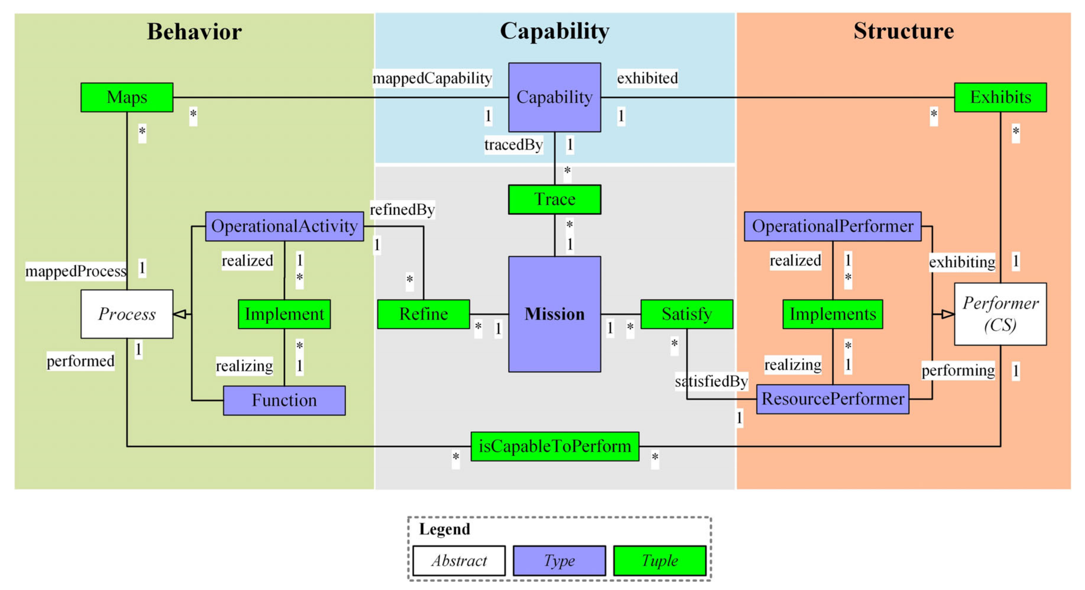
Figure 1. A simplified version of the SoS metamodel.
The representation of a mission in the metamodel, denoted by Type, is linked to other elements through three distinct sets of relationships defined by Tuple. These relationships include trace, refine, and satisfy, which respectively outline the capabilities required to achieve the mission, operational activities needed for behavioral analysis, and resource allocation from a structural perspective. To represent the constituent systems (CS) of the SoS, the Performer is used, which can be physical resources (ResourcePerformer) or logical resources (OperationalPerformer). As SoS is a collective term for multiple CSs, there is no single CS in the metamodel to represent the concept of SoS. Instead, the metamodel investigates how CSs implement their capabilities to comprehend and describe the SoS. The Process can be captured as an OperationalActivity to represent a logical process or function specified within the context of a ResourcePerformer capable of performing it.
3.2. OWL-Based Representation of SoS Metamodel
The proposed SoS metamodel comprises elements classified into Abstract, Type, and Tuple. Therefore, the corresponding OWL terms for these element types must be specified in the ontology space. The Protégé ontology editing software (version 5.5.0) [45] models the example elements presented in the SoS metamodel, as shown in Figure 2.
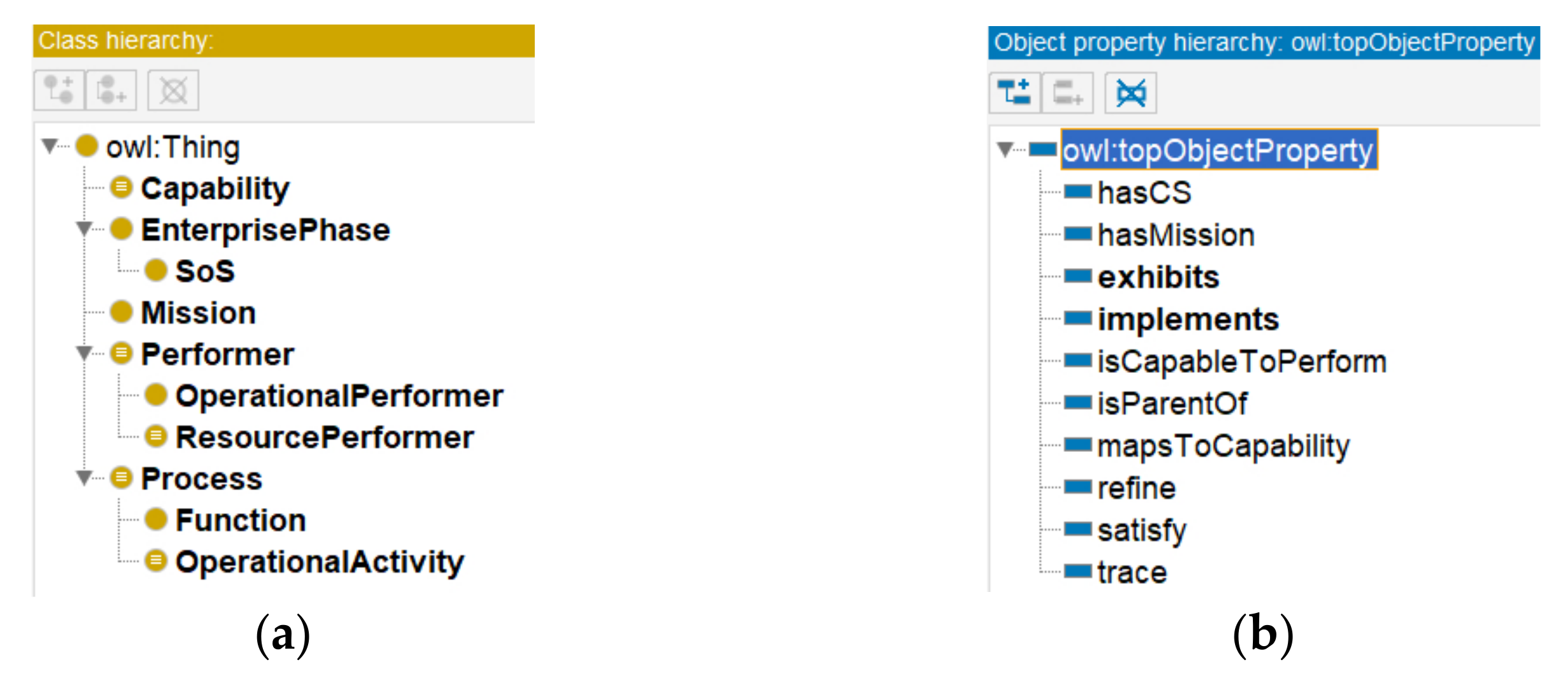
Figure 2. OWL representation. (a) OWL-based representation of the Type and Abstract, (b) OWL-based representation of the Tuple.
The Type is transformed into a class in ontology, as shown in Figure 2a, where an inheritance relationship links the “Performer” class and the “OperationalPerformer” class. Similarly, the Abstract is transformed into a class in ontology, exemplified by the “Process” and its sub-elements “Function” and “OperationalActivity”. While “Process” is an abstract class and cannot be instantiated in practical cases, serving only for analysis and reasoning purposes. However, the sub-classes “Function” and “OperationalActivity” can be instantiated, representing these instances as individuals in the ontology.
A Tuple means a relationship or flow between two elements and can be directly represented in OWL, which focuses on tuple relationships, such as “A contains B”. Therefore, the Tuple in the metamodel is transformed into an object property in ontology, as illustrated in Figure 2b. For example, the relationship between “Capability” and “Mission” can be represented as an object property named “trace”.
To address the fact that the concept of an SoS is not explicitly represented in the SoS metamodel, an SoS class is added to the ontology using the “EnterprisePhase” stereotype from the UAF DMM. The interconnection between the SoS and its constituent CSs is established through the “hasCS” object property, while the “hasMission” object property is employed to depict the connection between the SoS and its mission.
Based on the above analysis, Figure 3 shows the SoS ontologies modeled in Protégé.
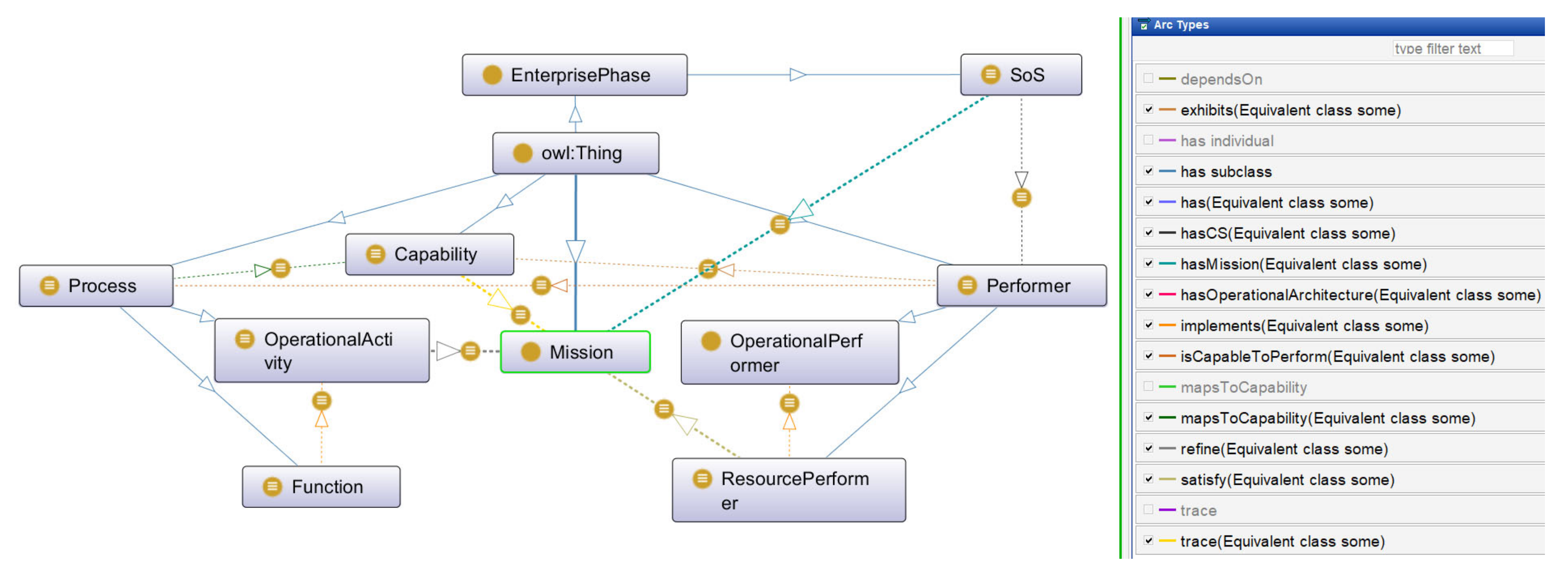
Figure 3. OWL-based representation of SoS ontologies.
3.3. Extending SoS Ontologies Based on Flow
The proposed metamodel and ontology offer fundamental concepts for comprehending SoS but require supplementary semantics to aid the development of architecture views. This section addresses this gap by incorporating relations, flows, and factors into the SoS ontologies. The rationale and related concepts are presented, followed by establishing the SoS capability ontology (SoSCO) and SoS operational ontology (SoSOO) for storing and processing the proposed relationships and flows.
3.3.1. Rationale and Related Concepts
SoS is distinguished from a single system by the managerial and operational independence of the CSs [46]. To fully describe and model SoS, strategic domain views are needed to account for “managerial independence”, and operational domain views are required to address “operational independence” [47]. This study focuses on both strategic and operational domains.
Selecting architecture views and their sequence for a domain is challenging due to various model kinds (e.g., taxonomy, structure, connectivity, and process), capturing unique descriptions of SoS architecture. Flow-based functional representation [46] is a common approach in SE to characterize functions as transformations of flows. However, analyzing SoS architecture requires considering multiple domains and model kinds, and various flows and relationships must be described to reflect the main concerns of the different model kinds.
This study proposes six model kinds and corresponding relationships and flows for them. Instead of solely relying on the model kind’s name, engineers can identify the focus of architecture views by examining the proposed relationships and flows. For example, a generalization relationship is defined as a hierarchical structure whereby a specialized (child) element is developed based on a more generalized (parent) element. The proposed context flow visually links general elements, enhancing the semantic interpretation of the generalization relationship. The context flow does not provide any specific properties of the flow but serves a schematic function within the relationship. A composition represents a whole–part relationship and is a type of aggregation. A dependency relationship between elements, similar to supporting functions [38], represents prerequisites that enable other elements. A connector flow summarizes exchanges of information, systems, personnel, and energy, among other things. A message flow defines specific communication between elements during an interaction. An edge flow signifies the flow of objects or information between activities, while a transition denotes a change in the state of the system or object being modeled.
This study defines relationships and flows based on the Tuple from IDEAS for architecture modeling in the strategic and operational domains. Figure 4 illustrates three relationships for capturing capabilities in the strategic domain and another three relationships and five flows for the operational domain. As illustrated in Figure 1, the performer exhibits capability, represented by activities capturing a logical process. The specific relationships/flows that describe the operational performer are OperationalContext, PerformerGeneralization, PerformerComposition, OperationalConnector, and OperationalMessage, while those used to describe the operational process are ActivityComposition, OperationalActivityEdge, and Transition. Three questions should be answered to construct AFs for SoS architecture based on the relationships and flows in the early design phase:
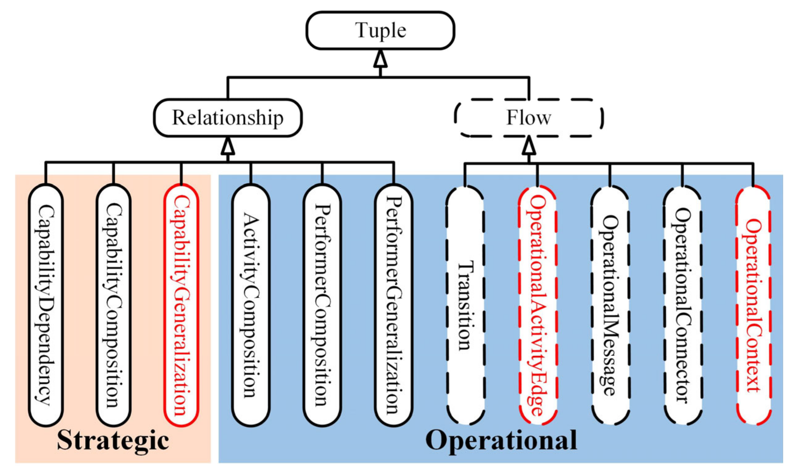
Figure 4. Flow-based representation in strategic and operational domains.
-
How to identify the general and specialized elements of the generalization relationship in the strategic domain?
-
How to identify the context flow in the operational domain based on the capability analysis?
-
How to identify the edge flow’s source, target, and swimlanes?
These questions connect the mission and capability analysis, strategic and operational domains, and operational engineering activity. The relationships/flows that correspond to these questions are highlighted in red in Figure 4 and require specific methods for identification and organization.
3.3.2. SoS Capability Ontology (SoSCO)
The UAF defines capabilities as being realized through combinations of ways and means. SoS metamodels frequently refer to capabilities [48][49][50], such as the “simple” and “complex” types that describe capability attributes [40]. However, these terms remain vague and require necessary attributes and relationships to support the SoS strategic architecture model process. Complementary capabilities related to each other through relationships can trace the mission, with each capability characterized by its attributes. Figure 5 presents the core terminology of SoSCO.
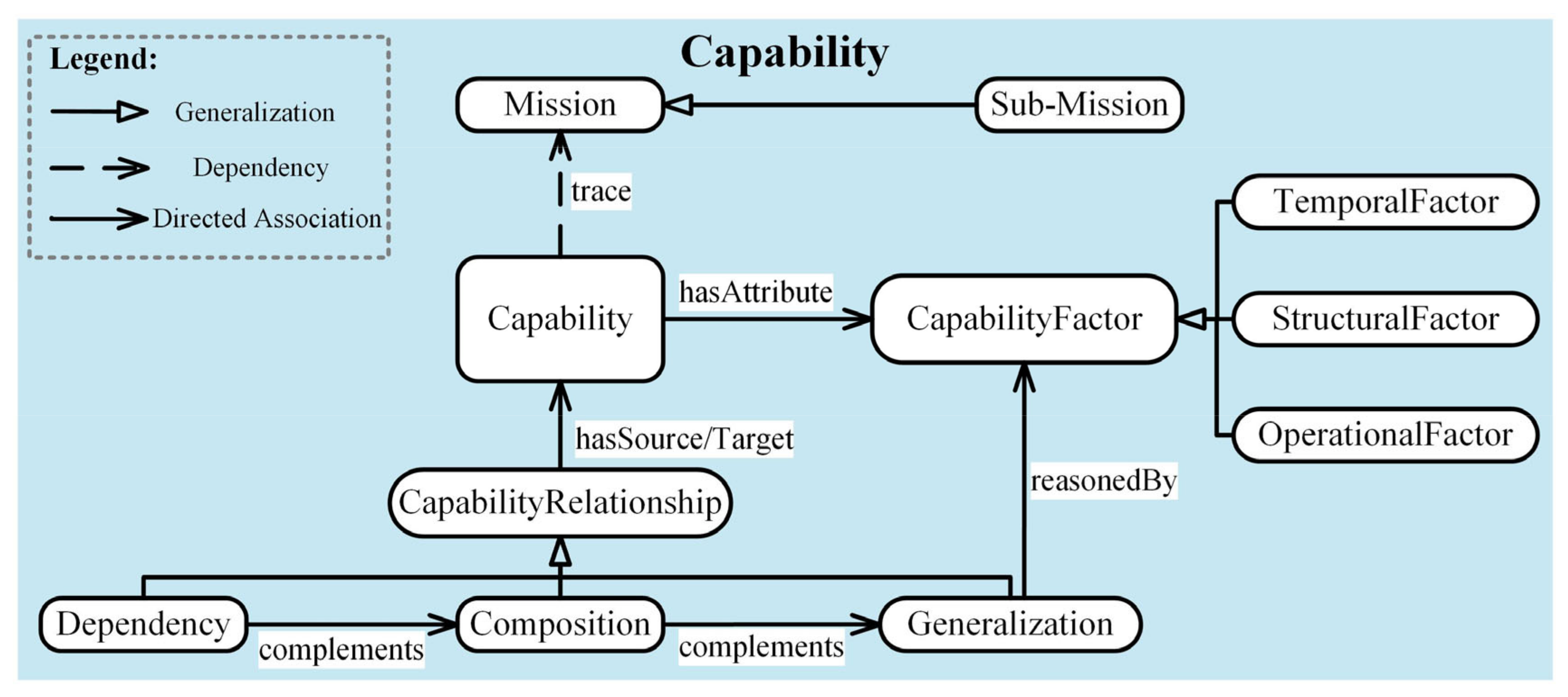
Figure 5. Core terminology of SoSCO.
The sub-mission is inherited from the mission to specify the top-level SoS mission breakdown. The trace relationship illustrates what capabilities should have to realize missions. However, when modeling an SoS with AFs, it is crucial to identify the relationships between capabilities and determine the appropriate modeling order. CapabilityRelationship, which encompasses Generalization, Composition, and Dependency, can be used for this purpose. Additionally, the concepts of CapabilityFactor, including TemporalFactor, StructuralFactor, and OperationalFactor, enrich the semantics of the ontology to reason about the general and specialized elements of the generalization relationship. TemporalFactor is a critical component of ensuring the coherence of capabilities with the strategic phase plan of the SoS. Specifically, TemporalFactor considers time-related factors that may influence the performance of constituent systems within an SoS, such as the duration of operations or the frequency of events. StructuralFactor specifies that capabilities are realized through various combinations of realistic entities. StructuralFactor refers to the physical and logical structure of the constituent systems in an SoS, such as the hardware and software components, the communication protocols, and the data formats. OperationalFactor provides information on the purpose of operational activities and physical functions to enrich the context of the above two factors. After establishing the generalization relationship, the description of capabilities can be complemented by composition and dependency relationships.
3.3.3. SoS Operational Ontology (SoSOO)
As the SoSCO emphasizes the relationship between capabilities (what), then it is necessary to make a description of the performers (who) can exhibit capabilities and activities (how) that can support capabilities. To this end, the SoS operational ontology (SoSOO) is defined as shown in Figure 6. The SoSOO illustrates the refinement of missions by mapping structure and behavior. The boxes with dashed lines represent the flows.
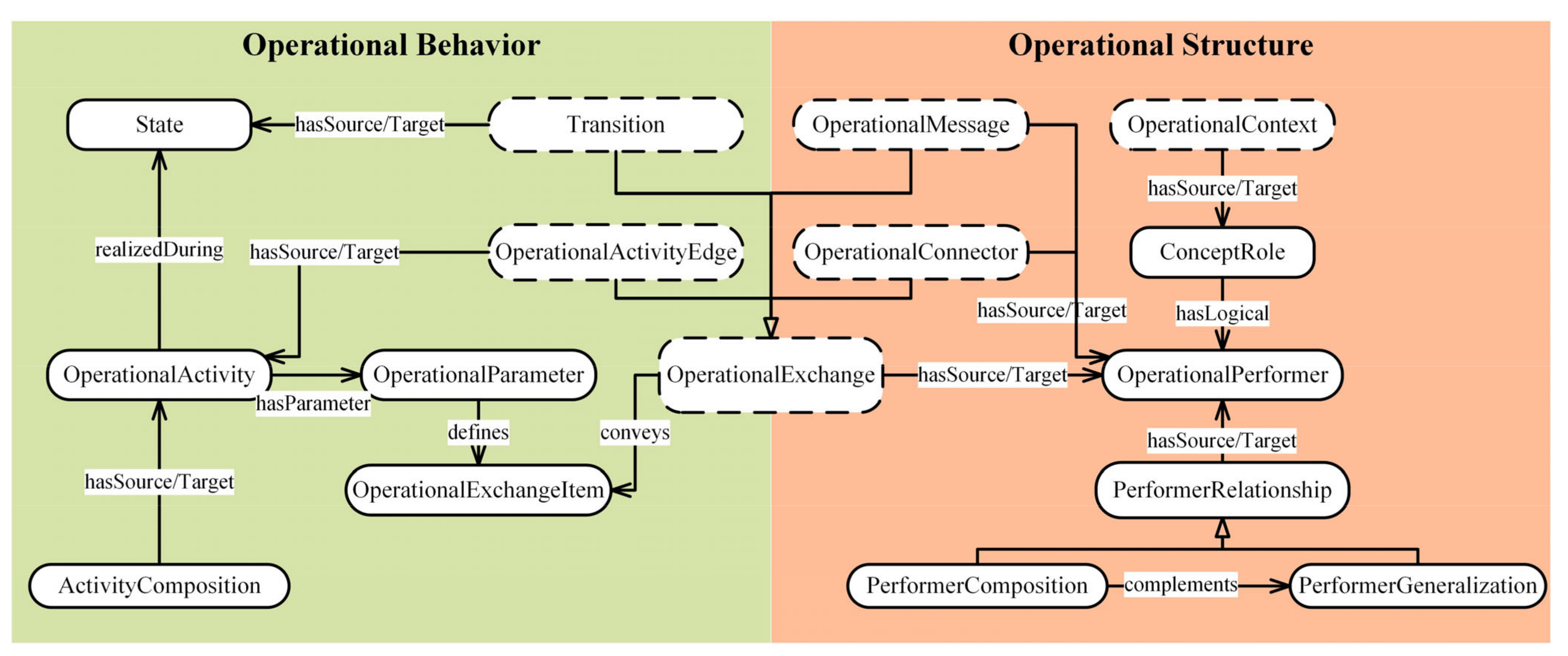
Figure 6. Core terminology of SoSOO.
OperationalPerformer is a logical entity that executes OperationalActivities to manipulate resources. ConceptRole denotes a role played by an asset or location in an SoS operational context [29]. OperationalContext provides a visual connection between high-level operational concepts. Although linking the operational structure with capabilities is straightforward, such as OperationalPerformer exhibits Capability, such mappings are too simplified to reflect the underlying relationships between operational ontologies. Hence, OperationalActivity is used to refine missions in the operational domain and support capabilities (mapsToCapability). Since capabilities specify their expected behaviors (OperationalActivity), and structures (OperationalPerformer) realize capabilities through the behaviors they can perform, matching the behaviors improves the mapping between capabilities and operational structure. The proposed flow-based representation introduces various flows in the SoS operational architecture to bridge structure and behavior. OperationalExchange asserts the flow’s existence between OperationalPerformers, which can be classified as follows: OperationalActivityEdge denotes the flow of resources (objects/information) between OperationalActivity; Transition indicates the state change of a single OperationalPerformer under the influence of the OperationalExchange with other OperationalPerformers and the internal OperationalActivityEdge; OperationalMessage shows the execution sequence of OperationalExchange among multiple OperationalPerformers in operational interaction scenarios.
References
- Maier, M.W. Architecting principles of systems-of-systems. In Proceedings of the 6th International Symposium, Chiang Mai, Thailand, 14–17 October 1996.
- Nielsen, C.B.; Larsen, P.G.; Fitzgerald, J.; Woodcock, J.; Peleska, J. Systems of Systems Engineering: Basic Concepts, Model-Based Techniques, and Research Directions. ACM Comput. Surv. 2015, 48, 1–41.
- OUSD (AT&L). Systems Engineering Guide for Systems of Systems; Pentagon: Washington, DC, USA, 2008.
- DeLaurentis, D.A.; Crossley, W.A.; Mane, M. Taxonomy to guide systems-of-systems decision-making in air transportation problems. J. Aircr. 2011, 48, 760–770.
- Okami, S.; Kohtake, N. Transitional complexity of health information system of systems: Managing by the engineering systems multiple-domain modeling approach. IEEE Syst. J. 2017, 13, 952–963.
- Fang, Z. System-of-Systems Architecture Selection: A Survey of Issues, Methods, and Opportunities. IEEE Syst. J. 2021, 16, 4768–4779.
- ISO/IEC/IEEE 42010; Systems and Software Engineering–Architecture Description. ISO/IEC/IEEE: Geneva, Switzerland, 2011; Volume 2011, pp. 1–46.
- U.S. Department of Defense. DoD Architecture Framework (DoDAF) ver 2.02. Available online: https://dodcio.defense.gov/Library/DoD-Architecture-Framework/ (accessed on 17 February 2023).
- DeLaurentis, D.; Raz, A.; Guariniello, C. MBSE for System-of-Systems. In Handbook of Model-Based Systems Engineering; Madni, A.M., Augustine, N., Sievers, M., Eds.; Springer International Publishing: Cham, Switzerland, 2020; pp. 1–29.
- Shirvani, F.; Beydoun, G.; Perez, P.; Scott, W.; Campbell, P. An Architecture Framework Approach for Complex Transport Projects. Inf. Syst. Front. 2021, 23, 575–595.
- INCOSE. INCOSE Systems Engineering Handbook: A Guide for System Life Cycle Processes and Activities; INCOSE: San Diego, CA, USA, 2015.
- Lock, R.; Sommerville, I. Modelling and analysis of socio-technical system of systems. In Proceedings of the 2010 15th IEEE International Conference on Engineering of Complex Computer Systems, Oxford, UK, 22–26 March 2010; pp. 224–232.
- Fang, Z.; Jin, W. Exploring Decision Patterns for Supporting DoDAF based Architecture Design. In Proceedings of the 2022 IEEE International Conference on Systems, Man, and Cybernetics (SMC), Prague, Czech Republic, 9–12 October 2022; pp. 2993–2999.
- OMG. Systems Modeling Language Specification Version 1.6. Available online: https://www.omg.org/spec/SysML/1.6 (accessed on 22 April 2023).
- Fitzgerald, J.; Larsen, P.G.; Woodcock, J. Modelling and Analysis Technology for Systems of Systems Engineering: Research Challenges; INCOSE: San Diego, CA, USA, 2012.
- Object Management Group. Unified Architecture Framework (UAF) Domain Metamodel v1.1. Available online: https://www.omg.org/spec/UAF/1.1/DMM/PDF (accessed on 17 February 2023).
- Wardhana, H.; Ashari, A.; Sari, A.K. Transformation of SysML Requirement Diagram into OWL Ontologies. Int. J. Adv. Comput. Sci. Appl. 2020, 11, 106–114.
- Knöös Franzén, L.; Staack, I.; Krus, P.; Jouannet, C.; Amadori, K. A Breakdown of System of Systems Needs Using Architecture Frameworks, Ontologies and Description Logic Reasoning. Aerospace 2021, 8, 118.
- Lin, J.; Fox, M.S.; Bilgic, T. A requirement ontology for engineering design. Concurr. Eng. Res. Appl. 1996, 4, 279–291.
- Bermudez-Edo, M.; Elsaleh, T.; Barnaghi, P.; Taylor, K. IoT-Lite: A lightweight semantic model for the Internet of Things. In Proceedings of the 2016 INTL IEEE Conferences on Ubiquitous Intelligence & Computing, Advanced and Trusted Computing, Scalable Computing and Communications, Cloud and Big Data Computing, Internet of People, and Smart World Congress (Uic/Atc/Scalcom/Cbdcom/Iop/Smartworld), Toulouse, France, 18–21 July 2016; pp. 90–97.
- Sales, D.C.; Becker, L.B.; Koliver, C. Informatics. The systems architecture ontology (SAO): An ontology-based design method for cyber–physical systems. Appl. Comput. Inf. 2022. ahead of print.
- Baek, Y.-M.; Song, J.; Shin, Y.-J.; Park, S.; Bae, D.-H. A meta-model for representing system-of-systems ontologies. In Proceedings of the 6th International Workshop on Software Engineering for Systems-of-Systems, Gothenburg, Sweden, 29 May 2018; pp. 1–7.
- Zachman, J.A. A framework for information systems architecture. IBM Syst. J. 1987, 26, 276–292.
- The Open Group. TOGAF-The Open Group Architecture Framework Version 9.2. Available online: https://www.opengroup.org/togaf (accessed on 28 March 2023).
- Ministry of Defence. Ministry of Defence. Ministry of Defense Architecture Framework. Available online: https://www.gov.uk/mod-architecture-framework (accessed on 28 March 2023).
- North Atlantic Treaty Organization. NATO Architecture Framework Version 4. Available online: https://www.nato.int/cps/en/natohq/topics_157575.htm (accessed on 28 March 2023).
- Odukoya, K.A.; Whitfield, R.I.; Hay, L.; Harrison, N.; Robb, M. An Architectural Description For The Application Of Mbse In Complex Systems. In Proceedings of the 2021 IEEE International Symposium on Systems Engineering (ISSE), Virtual Conference, 13 September–13 October 2021; pp. 1–8.
- Object Management Group. Unified Architecture Framework (UAF) Version 1.0. Available online: https://www.omg.org/spec/UAF/1.0/ (accessed on 17 February 2023).
- Object Management Group. Unified Architecture Framework (UAF) Version 1.2. Available online: https://www.omg.org/spec/UAF/1.2/Beta1/About-UAF/ (accessed on 17 February 2023).
- Object Management Group. Enterprise Architecture Guide for UAF. Available online: https://www.omg.org/cgi-bin/doc?dtc/21-12-13.pdf (accessed on 17 February 2023).
- Dandashi, F.; Hause, M.C. UAF for system of systems modeling. In Proceedings of the 2015 10th System of Systems Engineering Conference (SoSE), San Antonio, TX, USA, 17–20 May 2015; pp. 199–204.
- Eichmann, O.C.; Melzer, S.; God, R. Model-based Development of a System of Systems Using Unified Architecture Framework (UAF): A Case Study. In Proceedings of the 2019 IEEE International Systems Conference (SysCon), Orlando, FL, USA, 8–11 April 2019; pp. 1–8.
- Zhang, Y.; Xing, C.; Wang, Q.; Zhu, J. A UAF Based Method for Next Generation Air Traffic Management System Development. In Advances in Guidance, Navigation and Control, Proceedings of the 2020 International Conference on Guidance, Navigation and Control, ICGNC 2020, Tianjin, China, 23–25 October 2020; Springer: Singapore, 2022; pp. 4053–4063.
- Mori, M.; Ceccarelli, A.; Lollini, P.; Frömel, B.; Brancati, F.; Bondavalli, A. Systems-of-systems modeling using a comprehensive viewpoint-based SysML profile. J. Softw. Evol. Process 2017, 30, e1878.
- Browning, C.M.; Deal, J.; Mayes, S.; Arshad, A.; Rich, T.C.; Leavesley, S.J. Excitation-scanning hyperspectral video endoscopy: Enhancing the light at the end of the tunnel. Biomed. Opt. Express 2021, 12, 247–271.
- Graves, H. Integrating SysML and OWL. In Proceedings of the OWL: Experiences Directions, Chantilly, VA, USA, 23–24 October 2009.
- Zhu, W.; He, H.; Wang, Z. Ontology-Based Mission Modeling and Analysis for System of Systems. In Proceedings of the 2017 IEEE International Conference on Internet of Things (iThings) and IEEE Green Computing and Communications (GreenCom) and IEEE Cyber, Physical and Social Computing (CPSCom) and IEEE Smart Data (SmartData), Exeter, UK, 21–23 June 2017; pp. 538–544.
- Friedenthal, S.; Moore, A.; Steiner, R. A Practical Guide to SysML: The Systems Modeling Language; Morgan Kaufmann: Burlington, MA, USA, 2014.
- Cherfa, I.; Belloir, N.; Sadou, S.; Fleurquin, R.; Bennouar, D. Systems of systems: From mission definition to architecture description. Syst. Eng. 2019, 22, 437–454.
- Koutsopoulos, G.; Henkel, M.; Stirna, J. An analysis of capability meta-models for expressing dynamic business transformation. Softw. Syst. Model. 2021, 20, 147–174.
- Jamshidi, M. System of Systems Engineering: Innovations for the 21st Century; John Wiley & Sons: Hoboken, NJ, USA, 2008; pp. 1–591.
- Sage, A.P.; Rouse, W.B. Handbook of Systems Engineering and Management; John Wiley & Sons: Hoboken, NJ, USA, 2014.
- Morkevicius, A.; Bisikirskiene, L.; Bleakley, G. Using a systems of systems modeling approach for developing Industrial Internet of Things applications. In Proceedings of the 2017 12th System of Systems Engineering Conference (SoSE), Waikoloa, HI, USA, 18–21 June 2017; pp. 1–6.
- IDEAS Group. International Defence Enterprise Architecture Specification. Available online: https://en.wikipedia.org/wiki/IDEAS_Group (accessed on 28 March 2023).
- Musen, M.A. The protégé project: A look back and a look forward. AI Matters 2015, 1, 4–12.
- Maier, M.W. Architecting principles for systems-of-systems. Syst. Eng. 1998, 1, 267–284.
- Tirone, L.; Guidolotti, E.; Fornaro, L. A Tailoring of the Unified Architecture Framework’s Meta-Model for the Modeling of Systems-of-Systems. Proc. INCOSE Int. Symp. 2018, 28, 1691–1705.
- Hongyue, H.; Weixing, Z.; Ruiyang, L.; Qiaoyu, D. An executable modeling and analyzing approach to C4ISR architecture. J.Syst. Eng. Electron. 2020, 31, 109–117.
- Dridi, C.E.; Benzadri, Z.; Belala, F. System of Systems Engineering: Meta-Modelling Perspective. In Proceedings of the 2020 IEEE 15th International Conference of System of Systems Engineering (SoSE), Budapest, Hungary, 2–4 June 2020; pp. 000135–000144.
- Qi, Y.; Wang, Z.; Dong, Q.; He, H. Modeling and verifying SoS performance requirements of C4ISR systems. J. Syst. Eng. Electron. 2015, 26, 754–763.
More
Information
Subjects:
Others
Contributors
MDPI registered users' name will be linked to their SciProfiles pages. To register with us, please refer to https://encyclopedia.pub/register
:
View Times:
1.8K
Revisions:
3 times
(View History)
Update Date:
19 May 2023
Table of Contents


Notice
You are not a member of the advisory board for this topic. If you want to update advisory board member profile, please contact office@encyclopedia.pub.
OK
Confirm
Only members of the Encyclopedia advisory board for this topic are allowed to note entries. Would you like to become an advisory board member of the Encyclopedia?
Yes
No
${ textCharacter }/${ maxCharacter }
Submit
Cancel
Back
Comments
${ item }
|
${ item.createdUser.fullName }
${ item.createdAt }
${ item.vote }
${ item.reply }
Delete
${ reply.createdUser.fullName }
${ reply.createdAt }
${ reply.vote }
Delete
There is no reply to this comment~
${ item.replyTextCharacter }/${ item.replyMaxCharacter }
Submit
Cancel
More
No more~
There is no comment~
${ textCharacter }/${ maxCharacter }
Submit
Cancel
${ selectedItem.replyTextCharacter }/${ selectedItem.replyMaxCharacter }
Submit
Cancel
Confirm
Are you sure to Delete?
Yes
No